CanyCom CM 2103 User manual

Read this manual completely before operating or maintaining this machine.
Failure to follow safety precautions could result in serious injury or death.
Keep this manual for future reference by you and by all those who operate
and maintain this machine.
CHIKUSUI CANYCOM, INC.
90-1 Fukumasu, Yoshii-machi,
Ukiha-shi, Fukuoka, Japan 839-1396
Tel.+81-(0)943-75-2195 Fax.+81-(0)943-75-4396
Original Instructions
(in English)
Ride-on Brushcutter
CM 2103
Operator's Manual
5314 5205 001

http://www.canycom.co.jp/
■Sales Headquarters TEL +81-(0)943-75-2195 FAX +81-(0)943-75-4396
■
Foreign Trade Center
TEL +81-(0)3-3552-6277 FAX +81-(0)3-3552-6288
All rights reserved. Unauthorized use or reproduction of this material is prohibited.
Authorized Dealer
CHIKUSUI CANYCOM, INC.

Contents
1. Introduction 1
1.1 Purpose of This Manual ……………………………………………… 1
1.2 Structure of This Manual……………………………………………… 1
1.3 Warning Labels Attached to This Machine ………………………… 2
2. Warranty and After-sales Service 5
3. Rules for Safe Operation and Work 6
4. Component Names and Locations 11
5. Product Specifications 13
5.1 Specifications of This Product ………………………………………… 13
5.2 Details of Tool Bag……………………………………………………… 14
6. Operation 15
6.1 Preparation Before Operation ……………………………………… 15
6.1.1 Adding Fuel ………………………………………………………………………15
6.1.2 Checking Engine Oil Level and Adding Oil ……………………………………16
6.2 Starting ………………………………………………………………… 17
6.3 Operation Procedure ………………………………………………… 20
6.4 Stopping ………………………………………………………………… 21
6.5 How to Park …………………………………………………………… 21
6.6 Emergency Transferring ……………………………………………… 22
6.7 How to Avoid Slippage of Rear Wheels……………………………… 23
6.8 How to Operate Blade ………………………………………………… 23

6.9 How to Open and Close the Grass Outlet Cover…………………… 26
6.10 How to Operate the Deck Sliding Mechanism …………………… 27
6.11 How to use extinguisher ……………………………………………… 28
7. Maintenance 29
7.1 Periodic Inspection Table …………………………………………… 29
7.2 Fuel / Grease / Lubricant / Fluid Chart ……………………………… 32
7.3 Consumable (Replacement Parts) Chart …………………………… 33
7.4 Adding Oil ……………………………………………………………… 34
7.4.1 Engine Oil …………………………………………………………………………34
7.4.2 Transmission Oil …………………………………………………………………35
7.4.3 Differential Oil and Knuckle Oil …………………………………………………36
7.4.4 HST Oil ……………………………………………………………………………37
7.5 Lubrication and Greasing……………………………………………… 38
7.6 Adding Water to Battery ……………………………………………… 39
7.7 Cleaning ………………………………………………………………… 40
7.7.1 Air Cleaner Element ………………………………………………………………40
7.7.2 Ignition Plug ……………………………………………………………………… 41
7.7.3 Fuel Filter …………………………………………………………………………42
7.7.4 Fan Housing and Cooling Fan …………………………………………………42
7.8 Adjustments …………………………………………………………… 43
7.8.1 Driving V-Belt ……………………………………………………………………43
7.8.2 Blade Rotary V-Belt………………………………………………………………43
7.8.3 Rotary Stopper……………………………………………………………………44
7.8.4 HST Pedal…………………………………………………………………………45
7.8.5 Brake Pedal ………………………………………………………………………45

< Guarantee Certificate >
Attached to the back of this manual.
* Keep the guarantee certificate together with machine purchase receipt after you
have received instructions for handling this machine.
< Appendix >
"Instruction Manual for Engine"
* Be sure to read Appendix together with this manual.
7.8.6 Tire Pressure ……………………………………………………………………45
7.9 Replacement …………………………………………………………… 46
7.9.1 Oil Filter ……………………………………………………………………………46
7.9.2 HST Oil Filter ……………………………………………………………………46
7.9.3 Fuel Pipe, Engine Oil Drain Pipe, and HST Oil Tank Connection Hose ……46
7.9.4 Cutter Blade ………………………………………………………………………47
7.10 Maintenance After Use ……………………………………………… 48
8. Storage (Long-term Storage) 49
8.1 Vehicle Body …………………………………………………………… 49
8.2 Battery ………………………………………………………………… 50
8.3 Engine ………………………………………………………………… 50
8.3.1 Cleaning Air Cleaner Element …………………………………………………50
8.3.2 Replacing Engine Oil ……………………………………………………………51
9. Troubleshooting 52
10. Transporting This Vehicle 55

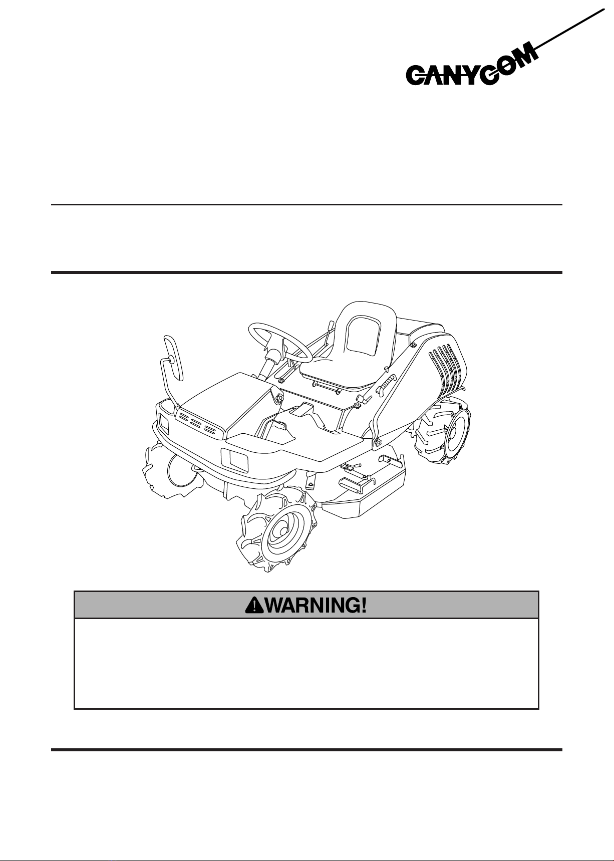
Notice to Users and Maintenance Personnel
Thank you for purchasing this machine.
Always be sure to read and understand this manual thoroughly before using
your machine. This will enable you to use it correctly.
* The machine can be very dangerous if the safety precautions
in this manual and on the labels attached to this machine
are not followed. Always follow the instructions and safety
precautions or serious injury or death could result.
* This machine is a work vehicle for mowing.
* Do not use it for other purposes. Any other use could be
dangerous.
* driving this machine on a public road or a road regarded as a
public road may be illegal, depending on local regulations.
* Do not modify this machine. Also do not remove the safety
cover of the body before running. A serious accident could
result.
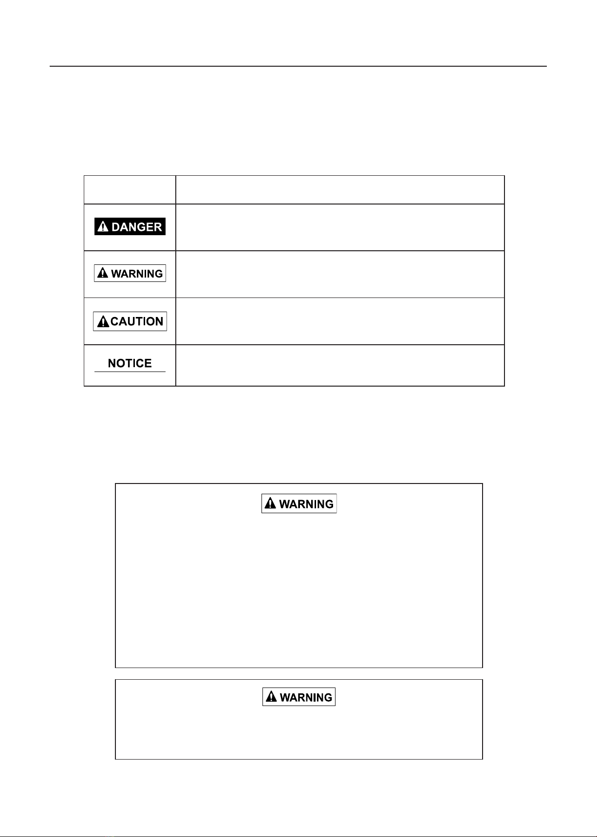
Warning Words Used in This Manual
To indicate the level of danger (or the degree of the failure), the following four signal words are
used to identify the safety messages in this manual. Their meanings are as follows:
Signal word Meaning
Indicates an imminently hazardous situation which, if not avoided
by following these instructions and precautions, could result in
serious injury or death.
Indicates a potentially hazardous situation which, if not avoided
by following these instructions and precautions, could result in
serious injury or death.
Indicates a potentially hazadous situation which, if not avoided by
following these instructions and precautions, may result in minor
or moderate injury.
This word is used for precautions that are recommended or to
emphasize the importance of information.

Introduction
- 1 -
1. Introduction
1.1 Purpose of This Manual
The purpose of this manual is to provide detailed information needed for the safe and
effective use of this machine to those who operate or maintain the machine.
1.2 Structure of This Manual
This manual contains the following chapters.
1. Introduction
This section explains the purpose and structure of the manual and the warnings used in the
manual. It also describes the warning labels attached to the machine.
2. Warranty and After-service
This section covers items related to the warranty and after-service for this machine.
3. Rules for Safe Operation and Maintenance
This section covers general safety items that must be followed when operating or using this
machine.
4. Component Names and Locations
This section explains the names and functions of the parts of the machine.
5. Product Specification
This section gives the specifications of this machine. It also gives details about the tool bag.
6. Operation
This section explains the preparations required before operating the machine, the order of
operation, and the method of operation.
7. Maintenance
This section gives information about periodic inspection, use of coolant, lubricants, and
grease, and cleaning, replacing, adjusting, and maintaining the machine after use.
8. Storage (Long-term Storage)
This section gives information about storage (long-term storage) of the machine.
9. Troubleshooting
This section describes possible causes and actions to take if problems occur.
10. Transporting Machine
This section explains the methods and precautions to take when transporting the machine.
Introduction

- 2 -
Introduction
5310M-0104-010E
1.3 Warning Labels Attached to This Machine
* Replace these labels immediately if they have been removed, have fallen off, or have
become illegible. Use the part numbers on the label to order replacement labels from
dealer.

Introduction
- 3 -
5310M-0104-020E

- 4 -
Introduction
5305 5327 000
5310M-0104-030E

– 5 –
5314M-0201-010E
2. Warranty and After-sales Service
Warranty
CHIKUSUI CANYCOM, Inc. provides warranties through local dealers. Consult your local dealer
regarding the details of your warranty.
After-sales Service
Please contact your CANYCOM distributor from whom you purchased your machine or our
Service Center regarding service orders or any questions or problems that may arise when using
the Ride-on Brush cutter.
Please refer to the product model that you own or use, the product serial number specified on
the model label (see illustration below for location of the label), the name of the manufacture of
the engine installed in your machine, and the engine model (listed in chapter 5 of this manual
"Specifications").
< Location of Model Label > < Model Label >
Warranty and After-sales Service
Availability of Replacement Parts
CHIKUSUI CANYCOM will make replacement parts for this machine available for seven years
after the end of this machine model’s production.
5310M-0200-000E

Rules for Safe Operation and Work
– 6 –
3. Rules for Safe Operation and Work
This chapter shows the general safety precautions to be observed during driving or operation.
Try to carry out driving or operation safely by being sure to follow the safety instructions in other
chapters as well.
Safety Precautions Before Operation
Protective Clothing
Wear clothes suitable for the operation of heavy equipment.
Protective footwear, long pants, and long-sleeved shirts are
recommended.
Pre-work Check
Perform the daily pre-operation check before starting the
machine.
Repair or replace damaged parts before starting the
machine.
Fuel Handling
Do not handle fuel or grease, service the engine, or
recharge the battery while smoking or when near an open
flame.
Do Not Carry Passengers on This Machine
This machine has one seat only: the operator seat.
It is extremely dangerous to drive this machine with
passengers. Never allow a person or persons other than
the operator to ride on the machine.
CM1-003
A1-001
CM1-002
CM1-001

Rules for Safe Operation and Work
– 7 –
Precautions on Crumbling Ground
Beware of driving in trenches and on banks. There is a
danger of the ground crumbling due to the machine weight.
When travelling on soft ground, drive slowly and safely.
Avoid Quick Starting, Acceleration, Turning
and Braking
Drive safely and avoid sudden changes of speed or
direction. Make sure the area around the machine is safe
for driving. Do not make sudden maneuvers or turn sharply
when driving on soft or wet ground; this can cause the
machine to lose traction or turn over.
Maintain Safe Speeds
Always drive at a safe speed.
Do Not Drive Recklessly
Do not operate this machine when under the influence of
alcohol or drugs, or when fatigued.
No one or under age 18 should operate this vehicle.
Avoid Starting, Accelerating, Turning, or Braking Quickly
CM2-003
CM2-002
CM2-001
CM1-004

Rules for Safe Operation and Work
– 8 –
Secure Area (No Admittance) During
Operation
Post notice boards before operation to show that job site
is under operation. If necessary, apply guard ropes to
enclose and restrict access so that people (especially
children) may not enter the work area and safety may be
ensured.
Beware of Flying Objects
Use care during operation to avoid throwing stones and
small objects toward nearby persons, animals, crops, cars
or other objects.
CM3-001
Use the Engine Speed to Help Brake When
Driving Down a Slope
Before driving down a slope, stop the machine temporarily
and lower the speed of the engine. Then, drive down the
slope at a low speed. Let the engine speed help decelerate
the machine.
Travel at a low speed on wet steel plates and in muddy
places. The machine may slip even on a gentle slope,
causing a serious accident. Stopping suddenly when
driving down a slope can throw the operator from the
machine or make the machine turn over, causing serious
injury or death.
Avoid Driving Across Slopes
Always travel straight up or down slopes.
Never travel across slopes or along contour lines.
Driving across steep slopes or along contour lines is
dangerous and may cause the machine to tip over, causing
serious injury or death. Avoid operating the side clutch
lever when the vehicle is positioned on sharply sloping
ground. If the lever must be used do so quickly and
carefully, taking care not to cause a reverse turn.
Safety Precautions When Operating
CM3-002
CM2-005
CM2-004

Rules for Safe Operation and Work
– 9 –
Avoid Operating in Dangerous Areas
Remove all obstacles from operation area. Avoid operating
on steep slopes or soft and rough ground and avoid
dangerous areas.
Safety Actions When Parking
When parking always apply brake and stop engine.
Always remove key.
Do Not Park on Unstable or Inclined Surfaces
Park the machine on stable, level, flat surfaces.
Do not park on unstable or inclined surfaces.
CM3-003
CM4-001
CM4-002
CM4-003
Precautions When Parking
Avoid Parking on Slopes
Avoid parking the machine on slopes.
If there are no other options, apply the parking brake
securely and block the wheels at the lower end .

Rules for Safe Operation and Work
– 10 –
CM5-001
CM5-002
Precautions When Performing Maintenance
Never Carry Out Maintenance with Engine
Running
Do not carry out maintenance with the engine running.
Always stop the engine before starting maintenance.
Ventilate Properly When Operating Indoors
When operating engine indoors, always ensure that there is
adequate ventilation to prevent poisoning by exhaust gas.

Component Names and Locations
- 11 -
4. Component Names and Locations
Locations
5314M-0400-000E
Component Names and Locations

- 12 -
Component Names and Locations
Component Names, Functions, and Operations
1 Main switch …………………… Start or stop engine with this switch.
* When the machine is not used remove and keep the key.
2 Accelerator lever ……………… Increases and decreases engine speed.
3 Choke lever …………………… When the lever is pulled out, the choke valve closes. When
lever is pushed in, the choke valve opens. Pull the lever when
starting the engine and push in after the engine is started.
4 HST pedal ……………………… When the pedal is depressed forward from the neutral position,
the machine moves forward. When the pedal is depressed
backward, the machine moves backward. The running speed
can be innitely adjusted by changing the depressed angle of
the pedal.
5 Auxiliary speed change lever … Use this lever when shifting speed to high / low levels.
WARNING: Do not change gears while driving.
6 Brake pedal …………………… Press to stop the machine when driving.
7 Parking brake lock lever ……… When the lock lever is lowered with the brake pedal pressed
down, the brake pedal is locked.
8 Differential lock lever ………… Use this lever when one of the rear wheels slips.
When the lever is moved to "ON", the differential lock
is engaged. When the lever is moved to "OFF", the
differential lock is disengaged (normal driving position).
* During normal driving, always put the lever to "OFF" position.
9 Blade height adjusting switch … Adjusts the cutter blade height.
10 Blade clutch lever …………… Turns blade power on and off.
When pushing this lever to "OFF", the cutter brake pulley is
engaged and the brake is applied.
11 Cutter blade cover …………… This cover prevents pebbles and foreign matter from shooting
out during operation. When replacing the cutter blade, open
this cover to facilitate the cutter blade replacement operation.
12 Head lamp ……………………… This light automatically lights up when the main switch is set to
"ON".
13 Engine oil warning lamp ……… When the main switch is turned to "ON", this lamp
lights up, and when the engine is started, it goes out.
It also lights up when engine oil becomes too hot while the
engine is running.
14 Hour meter …………………… This meter indicates the cumulative total operating time of this
machine in 0.1 hour increments.
15 Blade height monitor ………… The position (height) of the cutter blade is indicated by the
monitor.
16 Horn switch …………………… Press this switch to sound the horn.
17 Fire extinguisher ……………… Use in emergencies to extinguish fires on or away from
machine.

Product Specications
- 13 -
5. Product Specifications
5.1 Specifications of This Product
* Only use this product after understanding the specifications for this product.
Model/Type CM2103
Machine weight kg 415
Applicable job area m2/h 9000
Machine dimensions
Overall length mm 2065
Overall width mm 1110
Overall height mm 980
Wheel base mm 1460
Tread mm Front 810 / Rear 900
Minimum freeboard mm 115
Engine
Model - KAWASAKI FH641V
Type - Air-cooled 4-cycle gasoline
Cylinder (Bore × Stroke) mm 75.2 × 76.0
Total displacement cm3(cc) 675
Maximum output KW[ps]/rpm 14.7/3600 (21/3600)
Starting system Self-starter type
Fuel used Gasoline
Fuel tank capacity liters 15
Ignition plug no. - BPR4ES
Electrical
device
Battery type - 40B19R
Battery capacity V/AH 12 / 28
Product Specications

- 14 -
Product Specications
Model/Type CM2103
Travelling performance
Travelling
speed
Number of
speeds
F (Forward) - HST(variable speed)
R (Reverse) - HST(variable speed)
Low km/h 0 - 6.7
High km/h 0 - 10.0
Stability
inclination angle
(No-load)
Left degree 45
Right degree 45
Minimum turning radius m 1.9
Grade ability degree 25
Transmission oil capacity liters 2.0
Differential oil capacity liters 0.36
Power transmission
device
Main speed shift - HST
Steering device - Rack and pinion type round steering wheel
Brake type - Internal expanding type brake
Tire Front wheel - 4.00-7
Rear wheel - 17 × 8.00-8
Cutter blade
Cutter blade width mm 900
Cutter blade height mm 20 - 100 (free stage)
Blade type - Free knife & stepped stay
Amount of slide of cutter blade mm 150
* These specifications are subject to change without notice, for product improvement.
5.2 Details of Tool Bag
Part name Quantity Remarks
1 Operator's manual 1 This book
2 Instruction manual for engine 1
3 Plug wrench 1
4Closed wrench 1
Table of contents