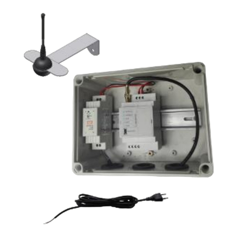
Capetti Elettronica Winecap EXP4IO Series User manual

EXP4IO-xx
User Manual
WA5047E_EXP4IO-xx_User Manual_R09
V4.6
CAPETTI ELETTRONICA s.r.l. - Strada Stratta 57
10090 CASTIGLIONE TORINESE - TORINO - ITALY
VAT 04837130014 - Phone 011.981.98.11 - Fax 011.981.98.210
1/11
1. Description.
EXP4IO expansions allows “M” series basestation interfacing with 4 INPUT/OUTPUT channels configurable in couples: analog,
digital, NTC and open collector contacts.
Developed to improve wireless basestation features (analog and digital inputs and outputs), are I/O expansion units to be directly
connected to expansion bus onboard on basestations. The expansion configuration is performed using the WineCapManager
software.
To connect expansions to basestation and setup the system for sample export toward outputs, refer to “WineCap System - User
Manual R29” chapter “Wireless basestation expansions”.
2. EXP4IO expansion types.
•EXP4IO-00: 4 NTC10K output channels expansion to be coupled with COSTER central units.
•EXP4IO-07: 3 NTC10K output channels expansion and 1 NTC1K output channel to be coupled with COSTER central units
provided with EXTERNAL NTC1K probe input.
•EXP4IO-33: 4 0÷10Vdc input channels expansion.
•EXP4IO-66: 4 0÷10Vdc output channels expansion.
For each MWDG basestation, up to 4 I/O expansion modules (with 4 channels each) can be connected.
Addresses, selectable by rotary switch, starts from position number 1 to position number 4; is recommended to place expansion
modules in address ascending order.
Picture 1 - Product image

EXP4IO-xx
User Manual
WA5047E_EXP4IO-xx_User Manual_R09
V4.6
CAPETTI ELETTRONICA s.r.l. - Strada Stratta 57
10090 CASTIGLIONE TORINESE - TORINO - ITALY
VAT 04837130014 - Phone 011.981.98.11 - Fax 011.981.98.210
2/11
3. EXP4IO expansion installation.
A. Connection must be done with all devices powered off, so shut down the basestation if needed.
B. Insert on DIN rail the EXP4IO-xx expansion module on the right side of the MWDG basestation.
C. Remove the terminal box upper caps of both devices and use the provided bridge to connect them.
D. Select the expansion module address, using a screwdriver working on the rotary switch, starting from “1” value for the first
expansion element and, in case of more devices to be added, assign addresses in ascending order up to four modules
maximum.
E. Power up the devices.
To connect I/O modules the RS485 communication channel must be modified from the external port to the internal bus.
This means that using modules block the simultaneous use of PLC devices on the external RS485 terminal.
Access to “Basestation” ➔“Properties”menu and select the “Settings” tab.
Picture 2 - EXP4IO expansion installation
Picture 3 - External modules setup
A
B
C
D
= 1
D
= 2
D
= 3
D
= 4
E

EXP4IO-xx
User Manual
WA5047E_EXP4IO-xx_User Manual_R09
V4.6
CAPETTI ELETTRONICA s.r.l. - Strada Stratta 57
10090 CASTIGLIONE TORINESE - TORINO - ITALY
VAT 04837130014 - Phone 011.981.98.11 - Fax 011.981.98.210
3/11
Select the Enable externals I/O modules option.
After this operation proceed to the identification and configuration of additional modules connected to the basestation.
This operation must not be performed in case the basestation connected is the MWDG-MB because it’s not necessary. In this case
the Enable externals I/O modules option will not be displayed on WineCapManager’s “Settings” window.
4. Connections layout.
5. EXP4IO - OUTPUT expansions (EXP4IO-00 - EXP4IO-07 - EXP4IO-66).
Using a EXP4IO output expansion, the basestation can convert a physical sample (temperature, humidity, etc.) in a analog signal between
0 and 10Vdc or in a resistive value.
CH2 +
GND
CH1 +
Expansion bus input
Expansion bus output
CH3 +
GND
CH4 +
Picture 4 - Connections layout
Picture 5 - Output expansions
Datalogger
WSDxx
3
3
3
2
3
1
3
4
MWDG
EXP4IO-xx

EXP4IO-xx
User Manual
WA5047E_EXP4IO-xx_User Manual_R09
V4.6
CAPETTI ELETTRONICA s.r.l. - Strada Stratta 57
10090 CASTIGLIONE TORINESE - TORINO - ITALY
VAT 04837130014 - Phone 011.981.98.11 - Fax 011.981.98.210
4/11
Example:
1. The WSDxx datalogger performs a physical phenomenon measurement (example: temperature, humidity).
2. The datalogger transmits by radio the acquired measure toward the MWDG basestation.
3. The MWDG basestation sends measure to EXP4IO-xx expansion module.
4. The expansion module transform this information in a voltage level between 0 and 10 Vdc.
Procedure:
1. Select the “Basestation” ➔“WLI Outputs and I/O modules manager”clicking on tag “I/O Modules”located in the right
upper side of the window, the following tab will appear:
Tabs of output management and I/O modules doesn’t maintain data in memory when closed; so, each time this tab is open
is strongly recommended to click the “Read” button to verify the previous content before any operation.
Operations “Write” and “Enroll” overwrite data. These operations cannot be undone.
2. Insert expansion device address (the one configured by rotary switch) in the field named “ID I/O module”, then click the “Enroll”
button.
The “Enroll” command must be used every time a new expansion module is connected or when an address has been
changed.
Picture 6 - I/O modules tab

EXP4IO-xx
User Manual
WA5047E_EXP4IO-xx_User Manual_R09
V4.6
CAPETTI ELETTRONICA s.r.l. - Strada Stratta 57
10090 CASTIGLIONE TORINESE - TORINO - ITALY
VAT 04837130014 - Phone 011.981.98.11 - Fax 011.981.98.210
5/11
In case the “Enroll” button has been clicked by mistake for a module previously programmed, a new configuration
procedure of logical channels is needed, because this operation restore them in default mode (channel with value as “0”) that
means logical channel not assigned.
“Read” command is used to verify if a module with assigned address has been previously configured, or if the “Enroll”
command succeed.
“Write” command is used to modify module’s parameters; for example to change the connection between logical channel
and virtual channels, enable it with a new channel or simply disable it with “0” value setup.
3. Open the “Basestation” ➔“WLI outputs and I/O modules manager” tab. The “Virtual channels configuration” page will
appear.
4. Select the datalogger/probe (sensor) by its MAC address, and the measure channel on the row corresponding to the
selected virtual output to configure the virtual outputs linked to measures coming from dataloggers/probes owned by
network.
In the following example the temperature channel of the 00003D01 datalogger has been linked to the first virtual channel
(Id n°1).
Picture 7 - Expansion device enrolling
Picture 8 –Expansion module MAC Address verify
Virtual Outputs

EXP4IO-xx
User Manual
WA5047E_EXP4IO-xx_User Manual_R09
V4.6
CAPETTI ELETTRONICA s.r.l. - Strada Stratta 57
10090 CASTIGLIONE TORINESE - TORINO - ITALY
VAT 04837130014 - Phone 011.981.98.11 - Fax 011.981.98.210
6/11
5. Once defined all links between dataloggers/probes (sensors) and virtual outputs, click the “Write configuration and other
settings to basestation” located in the bottom right side of the page and wait for the conclusion of parameter writing
process.
6. Select the “I/O modules” tab clicking the proper tag located in upper right side; the following page will appear:
7. Verify that the “MAC address” corresponds to the one on the label of the expansion device, then link its analog outputs
(channels 1,2,3 and 4) to virtual outputs defined at point 11 so click on the “Write” button to save the new configuration.
6. EXP4IO - INPUT expansions (EXP4IO-33).
Using the EXP4IO input expansion the basestation can acquire a physical sample (pulse, voltage or current) through a virtual datalogger
that own up to 4 channels.
Apparently this datalogger behave as a normal wireless datalogger, so saves values and parameters as name, sampling interval or
thresholds are adjustable.
The particular feature is that the virtual datalogger own a MAC code equal to the EXP4IO-xx module and the battery life and radio
quality signals were respectively always to 7 and 0dBm.
Picture 9 - Channel association example
Verify the MAC Address
Picture 10 - Virtual datalogger visualization

EXP4IO-xx
User Manual
WA5047E_EXP4IO-xx_User Manual_R09
V4.6
CAPETTI ELETTRONICA s.r.l. - Strada Stratta 57
10090 CASTIGLIONE TORINESE - TORINO - ITALY
VAT 04837130014 - Phone 011.981.98.11 - Fax 011.981.98.210
7/11
Procedure:
1. Select the drop down menu “Basestation”➔“WLI Outputs and I/O modules manager”and click the tag “I/O Modules”
located in the upper right side , the following window will appear:
2. Insert the expansion device address (the one configured by rotary switch) inside the field named “ID I/O module”, then click the
“Enroll” button.
3. In some cases the input type can be modified (contact, energy, pulse).
4. It’s also allowed modify the scale factor and the scale offset to adapt the sampled value from the measure channel to the
input value dynamic.
The coefficient to be introduced must be previously multiplied by the initial scale factor and inserted in the “Scale Offset
[V]” field.
The system will multiply this value by the sampled measure. The initial scale factor, by default, corresponds to device
resolution, that is the minimum unit readable.
5. The “Write” command is used to modify module’s parameters and make them definitive.
Reading again the system configuration “Basestation” ➔“Read sensors configuration” the virtual datalogger will appear in the list
and will be operative to acquire received values.
Picture 11 - Virtual datalogger setup

EXP4IO-xx
User Manual
WA5047E_EXP4IO-xx_User Manual_R09
V4.6
CAPETTI ELETTRONICA s.r.l. - Strada Stratta 57
10090 CASTIGLIONE TORINESE - TORINO - ITALY
VAT 04837130014 - Phone 011.981.98.11 - Fax 011.981.98.210
8/11
7. EXP4IO-00 and EXP4IO-07 install.
The EXP4IO-00 and EXP4IO-07 expansions allows a SELF-LEARNING procedure, to recognise the connection input type (voltage and
current of the reading circuit).
After physically connected the module’s outputs to related inputs and powered up all the device perform the following procedure (in
case of EXP4IO-07 the channel #4 must be connected to NTC1K “External Probe” input):
Input self-learning procedure
1. Connect the COSTER basestation’s inputs to EXP4IO expansion outputs.
2. Power up the system.
3. Keep pressed SW1 and SW2 keys for two seconds long, LD1 and LD2 leds will turn off:
4. Press SW1 for one second long. LD1 led flash in GREEN and the self-learning procedure for channel 1 starts. LD2 led is off.
At the end of procedure, LD1 will have a fixed light showing the result of self-learning procedure: GREEN=PASS, RED=FAIL.
5. Premere nuovamente SW1, la procedura si ripete lampeggiando LD1 ma apprende il canale 2. Press again SW1, the
procedure starts again with LD1 flashing but channel 2 starts learning.
6. Press SW2 for one second long. LD2 led flash in GREEN and the self-learning procedure for channel 3 starts. LD1 led is off.
At the end of procedure, LD2 will have a fixed light showing the result of self-learning procedure: GREEN=PASS, RED=FAIL.
7. Press again SW2, the procedure starts again with LD2 flashing but channel 4 starts learning.
8. Keep pressed SW1 and SW2 keys for two seconds long to exit from the self-learning procedure. LD1 and LD2 leds will have
fixed green light.
Invalid measure or offline probe condition.
In case the probe/datalogger presents an INVALID measure condition (damaged transducer) or probe/datalogger is in radio OFFLINE
condition (radio range not sufficient or battery exhausted), the EXP4IO module put outputs in high impedance status, to emulate an NTC
physical disconnection from related COSTER device’s input.
This condition can be detected as malfunction and can be managed properly programming the controller and, in case, highlighting
the fail status.
This condition is also detected when the device is powered on, and is maintained until measures are received by probes/dataloggers,
which update output status with desired values.
Picture 12 - Self learning procedure - Leds and keys positioning
LD2
LD1
SW1
SW2

EXP4IO-xx
User Manual
WA5047E_EXP4IO-xx_User Manual_R09
V4.6
CAPETTI ELETTRONICA s.r.l. - Strada Stratta 57
10090 CASTIGLIONE TORINESE - TORINO - ITALY
VAT 04837130014 - Phone 011.981.98.11 - Fax 011.981.98.210
9/11
8. Technical Information.
Power Supply
24Vdc from basestation
Programmable Functionality
•4 analog inputs (0÷10Vdc/0÷5Vdc/4÷20mA)
•4 digital inputs
•4 NTC10K inputs
•4 analog outputs (0÷10Vdc/0÷5Vdc)
•4 NTC10K and NTC1K (“Coster” emulation) outputs
•4 “open collector” digital outputs
Sealing
IP30
Dimensions
90x52x58mm
Weight
50g
Mounting
DIN bar
Expansion Connection
Through specific connector
I/O Connections
Through screw terminal block
9. Ordering code nomenclature.
EXP4IO
-
n
n
0
CH1 and CH2 → NTC10K SAB010 outputs
1
CH1 and CH2 → NTC inputs
2
CH1 and CH2 → pulse counter
3
CH1 and CH2 → 0÷10Vdc analog inputs
4
CH1 and CH2 → 0÷5Vdc analog inputs
5
CH1 and CH2 → 4÷20mA analog inputs
6
CH1 and CH2 → 0÷10Vdc analog outputs
0
CH3 and CH4 → NTC10K SAB010 outputs
1
CH3 and CH4 → NTC inputs
2
CH3 and CH4 → pulse counter
3
CH3 and CH4 → 0÷10Vdc analog inputs
4
CH3 and CH4 → 0÷5Vdc analog inputs
5
CH3 and CH4 → 4÷20mA analog inputs
6
CH1 and CH2 → 0÷10Vdc analog outputs
7
CH3 output → NTC 10K SAB010
CH4 output → NTC 1K SAE001 (external probe)
Example:
EXP4IO-66 All channels configured as 0÷10Vdc outputs.

EXP4IO-xx
User Manual
WA5047E_EXP4IO-xx_User Manual_R09
V4.6
CAPETTI ELETTRONICA s.r.l. - Strada Stratta 57
10090 CASTIGLIONE TORINESE - TORINO - ITALY
VAT 04837130014 - Phone 011.981.98.11 - Fax 011.981.98.210
10/11
10. Mechanical dimensions.
Picture 13 - Mechanical dimensions
90mm
52mm
58mm

EXP4IO-xx
User Manual
WA5047E_EXP4IO-xx_User Manual_R09
V4.6
CAPETTI ELETTRONICA s.r.l. - Strada Stratta 57
10090 CASTIGLIONE TORINESE - TORINO - ITALY
VAT 04837130014 - Phone 011.981.98.11 - Fax 011.981.98.210
11/11
11. Reference standards.
EN 61010 -1
For electromagnetic compatibility
EN 61000 - 3 - 2
EN 61000 - 3 - 3
EN 300 220 -2
EN 301 489 - 03
EN 61000 - 6 -1
This symbol indicates that this product is compliant with the European Directive 2011/65/CE that restricts
the use of substances in the manufacturing of electronic devices.
The “WEEE” logo on the label indicates that this product is compliant with the "WEEE" EC Directive.This
symbol (valid only in the European Union countries) indicates that the product it is applied to, MUST NOT
be discarded with ordinary household or industrial waste, but must be sent to an authorized reception
point. The end user should contact the device provider, either the manufacturer or the reseller, in order
to agree a collection and disposal process, after having checked the terms and conditions of sale.
The features shown may be subject to change without notice.
IT190200000111
61
Table of contents
Other Capetti Elettronica Gateway manuals