Capintec CRC-712MX User manual

CRC®-712MX
RADIOISOTOPE DOSE
CALIBRATOR
OWNER’S MANUAL
Capintec, Inc.
Sales and Marketing
and Customer Support
6 Arrow Road
Ramsey, NJ 07446
Phone (800) ASK-4CRC
Fax (201) 825-1336
Capintec, Inc.
Service Center
620 Alpha Drive
Pittsburgh, PA 15238
Phone (800) 227-6832
Fax (412) 963-0610
Copyright©1992 Capintec, Inc.
CRC®is a registered trademark of Capintec, Inc.
U.S. Patents - 3,748,476 and 3,840,745
ALL RIGHTS RESERVED
Manual Stock No. 9250-0068
Rev. C – January 2008


CAPINTEC, INC. CRC®-712MX
TABLE OF CONTENTS
PREFACE
SAFETY................................................................................................................................1-1
SYMBOL DEFINITIONS....................................................................................................1-1
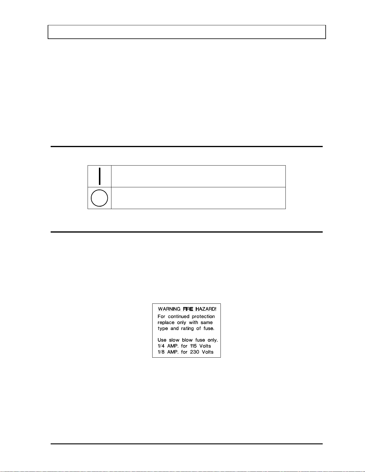
WARNING AND CAUTION LABELS.................................................................................1-1
CAUTIONS AND NOTES ..................................................................................................1-3
GENERAL SAFETY TIPS..................................................................................................1-4
FUNCTIONAL & TECHNICAL DESCRIPTION....................................................................2-1
FUNCTIONAL DESCRIPTION ..........................................................................................2-1
FEATURES........................................................................................................................2-1
TECHNICAL DESCRIPTION.............................................................................................2-3
Warm Up Period.............................................................................................................2-3
Environment Requirements............................................................................................2-3
Power Requirements......................................................................................................2-3
Dimensions ....................................................................................................................2-4
Performance ..................................................................................................................2-5
GENERAL OPERATING INSTRUCTIONS ..........................................................................3-1
GENERAL..........................................................................................................................3-1
PANEL DESCRIPTIONS...................................................................................................3-1
Front Panel ....................................................................................................................3-1
Back Panel.....................................................................................................................3-4
SYSTEM SETUP...................................................................................................................4-1
GENERAL..........................................................................................................................4-1
RECEIVING CONDITION EXAMINATION........................................................................4-1
UNPACKING AND INSTALLATION..................................................................................4-1
ASSEMBLY .......................................................................................................................4-2
ENVIRONMENT REQUIREMENTS ..................................................................................4-3
POWER REQUIREMENTS ...............................................................................................4-3
Readout .........................................................................................................................4-3
Printers...........................................................................................................................4-3
INITIAL TURN ON PROCEDURES...................................................................................4-4
ACCEPTANCE TESTING..................................................................................................4-4
GENERAL OPERATIONAL SETUP..................................................................................4-5
Locking the Curie or Becquerel Mode of Operation.......................................................4-5
Reassignment of a Preset Push-Button.........................................................................4-6
QUALITY ASSURANCE & ACCEPTANCE TESTING.........................................................5-1
GENERAL..........................................................................................................................5-1
ACCEPTANCE TESTING..................................................................................................5-1
Geometry Test ...............................................................................................................5-1
January 08 TABLE OF CONTENTS TOC-1

CAPINTEC, INC. CRC®-712MX
Daily Tests.....................................................................................................................5-1
Quarterly Tests..............................................................................................................5-3
Annual Tests..................................................................................................................5-5
MEASUREMENT PROCEDURES .......................................................................................6-1
GENERAL .........................................................................................................................6-1
PRE-MEASUREMENT PROCEDURES............................................................................6-1
PRESET ISOTOPE MEASUREMENT..............................................................................6-1
OTHER ISOTOPE MEASUREMENTS..............................................................................6-2
DOSE ASSAY PROCEDURE ...........................................................................................6-2
ADDITIONAL CALIBRATION NUMBERS.........................................................................6-3
Direct Calibration with Certified Standard Sources........................................................6-3
Intercomparison Calibration with a 12 Atmosphere Chamber .......................................6-4
PRINTING A RECORD OF THE MEASUREMENT..........................................................6-4
CLEANING AND MAINTENANCE.......................................................................................7-1
GENERAL .........................................................................................................................7-1
CLEANING INSTRUCTIONS............................................................................................7-1
PREVENTATIVE MAINTENANCE....................................................................................7-2
SERVICING.......................................................................................................................7-2
LINE VOLTAGE SELECTION/FUSE REPLACEMENT.....................................................7-2
Readout Fuses ..............................................................................................................7-2
Printer Fuse...................................................................................................................7-3
TROUBLESHOOTING ......................................................................................................7-4
Nothing appears on the display.....................................................................................7-4
High background indication ...........................................................................................7-4
Indication of significant negative activity........................................................................7-4
Printer will not respond..................................................................................................7-4
ACCESSORIES AND REPLACEMENT PARTS...............................................................7-5
Environmental Shield.....................................................................................................7-5
Positron Shield...............................................................................................................7-5
Hot Cell Chamber Mounting Flange ..............................................................................7-5
Data Logging Printer......................................................................................................7-6
RS-232C Computer Interface........................................................................................7-6
Calicheck.......................................................................................................................7-6
SHIPPING .........................................................................................................................7-7
APPENDIX I – Principle of the Calibrator
APPENDIX II – Table of Calibration Setting Numbers
APPENDIX III – Multiplication Factors For Non-Equilibrium Radioisotopes
INDEX
WARRANTY
TOC-2 TABLE OF CONTENTS January 08

CAPINTEC, INC. CRC®-712MX
PREFACE
Thank you for purchasing the Capintec, Inc. CRC®-712MX Radioisotope Dose Calibrator.
Every effort has been made to insure that the information in this document is complete,
accurate, and up-to-date. Capintec, Inc. assumes no responsibility for the results of errors
beyond its control. Mention of products manufactured by other companies does not
necessarily constitute endorsement by Capintec, Inc.
Please address any comments pertaining to this manual to:
CAPINTEC, Inc.
620 Alpha Drive
Pittsburgh, PA 15238
Phone (412) 963-1988
Fax (412) 963-0610
CRC®-712MX and CII are registered trademarks of Capintec, Inc.
SYSTEM DESCRIPTION
The CRC®-712MX Radioisotope Dose Calibrator consists of the following:
•Readout Unit
•Chamber(s)
•Power Cord
•Printer (optional)
ELECTROMAGNETIC INTERFERENCE POTENTIAL
This equipment generates radio frequency energy and, if not installed and used in
accordance with the instructions, may cause harmful interference to nearby devices.
However, there is no guarantee that interference will not occur in a particular installation. If
this equipment does cause harmful interference, the user is encouraged to try to correct the
interference by one of the following measures:
•Increase the separation between the equipment and the affected device.
•Plug the unit into an outlet on a circuit different from that to which the affected device
is connected.
If this fails to correct the problem, please contact Capintec’s Authorized Service Center.
January 08 PREFACE i

CAPINTEC, INC. CRC®-712MX
IMPORTANT SAFETY INFORMATION
The CRC®-712MX measurement system has been carefully designed to give you years of
safe and reliable performance. As with all electrical equipment, however, there are basic
precautions you must observe to avoid injuring yourself, the patient or damaging the
equipment.
•Follow the unpacking and assembly instructions document, and read this manual
carefully before using this equipment. Be sure to save all provided documents for
future reference.
•Understand all warning and caution labels as explained in CHAPTER 1: SAFETY
before operating this equipment.
ii PREFACE January 08

CAPINTEC, INC. CRC®-712MX
CHAPTER 1
SAFETY
These warnings and instructions for use form an integral part of the CRC®-712MX and must
therefore be kept available for consultation at all times. Precise compliance with the
instructions is an essential condition for normal use, correct application and thus safety of the
user.
SYMBOL DEFINITIONS
“ON” (power)
“OFF” (power)
WARNING AND CAUTION LABELS
Located on the back of the Readout Unit is a label, (Figure 1-1), providing the system power
requirements, and the replacement fuse values for power line voltages.
Please reference CHAPTER 7: CLEANING AND MAINTENANCE for instructions on how to
change the fuses and line voltage of the CRC®-712MX.
A fire hazard may exist if the wrong size of fuse is installed.
Figure 1-1
Located on the Power Cord is a label, (Figure 1-2), indicating that the grounding reliability
can only be achieved when the equipment is connected to an equivalent receptacle marked
hospital only or hospital grade..
January 08 SAFETY 1 - 1

CAPINTEC, INC. CRC®-712MX
Figure 1-2
Located on the chamber are 2 labels.
The first label (Figure 1-3) contains statements denoting not to remove the cover because
there are no adjustments that the user can perform in the chamber.
Figure 1-3
The second label (Figure 1-4) is located in three places (on the bottom of the chamber, on
the 150 Volt Battery pack inside the chamber & on the cover of the main power supply in the
readout unit) and pertains to the electrical safety of the chamber and readout. It is necessary
because of the high voltage present (approximately 150 volts) on the Battery board installed
in the chamber and the line voltage inside of the readout. A screwdriver is necessary to
remove the covers to both the chamber and the readout.
Figure 1-4
1 - 2 SAFETY January 08

CAPINTEC, INC. CRC®-712MX
CAUTIONS AND NOTES CAUTION
Only qualified/trained personnel should operate this unit.
CAUTION
If the equipment is used in a manner not specified in this manual, the protection provided by
the equipment may be impaired.
CAUTION
No internal adjustments inside the chamber or readout that may be performed by the user
within the conditions of the warranty. Due to the presence of high voltages, opening the
cover with the system plugged in may be hazardous. Refer all servicing to qualified
personnel.
CAUTION
Never use the calibrator without the well liner in place. Liners are inexpensive and easy to
replace. A contaminated chamber is a very costly mistake. If the unit becomes contaminated
remove the liner and clean the unit as stated in CHAPTER 7: CLEANING AND
MAINTENANCE before operating.
CAUTION
Care must be exercised when moving the instrument or when maintenance is performed.
The shielded cylinder is heavy (13.6 kg or 30 lb). In order to provide the required sensitivity,
the wall of the ionization chamber is extremely thin and the chamber is filled with pressurized
gas. It is therefore, essential to avoid mechanical shock or vibration of any kind.
CAUTION
When working with a heavy sample (especially a CapMac or Moly Assay Canister) always
lower it gently into the chamber well. Dropping any heavy object into the well can cause
permanent, expensive damage.
CAUTION
It is desirable to leave the unit powered at all times in order to prevent moisture absorption
and to maintain the stability of the instrument (especially if the instrument is subjected to high
humidity or low temperature).
CAUTION
The sensitivity of the chamber is somewhat dependent upon the vertical position of the
sample within the well. All calibrations were done with a Standard Sample placed in the
supplied sample holder (dipper). It should be noted that in this configuration, the sample is
not quite at the bottom of the well. If, for any reason, you make a measurement without using
the dipper, be sure that the sample is in the correct vertical position. Both the CapMac and
the Standard Moly Assay Canister maintain the same position as the dipper.
January 08 SAFETY 1 - 3

CAPINTEC, INC. CRC®-712MX
CAUTION
Use of accessories not listed in this manual, may compromise the compliance of this product
to IEC 60601-1. Therefore, only recognized accessories shall be used at all times. Also the
Electromagnetic Interference (EMI) may be compromised which may affect other devices
located in the same area as the CRC®-712MX or the CRC®-712MX may become susceptible
to EMI.
CAUTION
The unit contains lead. Appropriate caution should be taken if the interior of the unit is
exposed. The unit should be disposed of in accordance with local and national regulations.
CAUTION
The unit contains a Lithium Battery. This should be disposed of in accordance with local and
national regulations.
CAUTION
The user should always verify the validity of any measurement or test result in order to
minimize measurement errors.
NOTE
It is recommended that periodic re-calibration of the unit be performed by Capintec’s
Authorized Service Center to guarantee that the instrument's high reliability is maintained.
GENERAL SAFETY TIPS
•Unplug the equipment before cleaning it. Use only a damp cloth; do not use solvents
or aerosol cleaners.
•To protect the equipment from overheating, do not use the equipment directly in front
of a radiator or heat register.
•Do not use the equipment near water, or spill liquids of any kind into the equipment.
•Be sure that your power source matches the rating listed on the CRC®-712MX
calibrator.
•The CRC®-712MX power cord has a grounded, 3-prong plug as a safety feature, and
it will only fit into a grounded outlet. Do not use an adapter to defeat the grounding.
•To avoid damaging the power cord, do not place anything on it or place it where it will
be stepped on. If the cord becomes damaged, replace it immediately.
•Aside from the routine maintenance described in this manual, do not try to service
this equipment yourself. Do not make any adjustments other than those outlined in
this manual, as you may in-validate the calibration or cause damage requiring
extensive repair work. Refer servicing to qualified service personnel.
1 - 4 SAFETY January 08

CAPINTEC, INC. CRC®-712MX
CHAPTER 2
FUNCTIONAL & TECHNICAL
DESCRIPTION
FUNCTIONAL DESCRIPTION
The CRC®-712MX Radioisotope Dose Calibrator provides a precise, accurate, fast and very
convenient method of measuring the activity of a radioisotope at the time and place of its
application.
The CRC®-712MX Radioisotope Does Calibrator has been specifically designed for extra
high activity radioisotope measurements which are required for P.E.T centers, for
radiopharmaceutical applications, research or other related activities.
When a sample of a known radioisotope is placed in the chamber well in the appropriate
geometry and the proper calibration number is set, the activity of the sample will be displayed
with the proper units on the Readout unit.
Note: For a detailed description of the basic principles of the calibrator, see to APPENDIX I:
PRINCIPLE OF THE CALIBRATOR.
FEATURES
•Activity measurements are performed by state of the art electronic circuits in
conjunction with a one atmosphere ionization chamber possessing extremely high
sensitivity and stability.
•Curie or Becquerel units of measurement are selected by a rotary switch that can be
locked in either position.
•An 8-button measurement range switch provides unambiguous manual selection or
automatic selection of 6 activity measurement ranges. Manual range selection
provides the shortest measurement time when numerous measurements are being
taken in the same activity range. Automatic range selection provides the fastest
measurement when the activity range of the sample is not known.
•Extra large 4-digit numeric readout display with a floating decimal point: 0.8” high (20
mm.). Back-lighted units of measurement symbols.
•Eight preset push-buttons are provided for quick selection of the calibration number of
the most often used radioisotopes. The assignment of any of the eight push-buttons
may be changed by the user for his or her particular requirements.
•Confirmation of the instrument functions and all the required adjustments can be
made with fingertip operation. (Zero, Background, Bias Test)
January 08 FUCTIONAL & TECHNICAL DESCRIPTION 2 - 1

CAPINTEC, INC. CRC®-712MX
•Reliable measurements with a resolution as low as .001 millicuries (.0001 giga-
becquerels) and a top range of 800 Curies (20.00 tera-becquerels) are provided for
most radioisotopes.
•The calibration numbers for 12 radionuclides are provided in Appendix II of the
owner’s manual. The Calibration Potentiometer sets the gain for the specific
radionuclide that is being measured. A 3-digit counter on the Potentiometer insures
precise setting of the calibration number.
•The CRC®-712MX Model Calibrator can have a total of 5 remote Ionization Chambers
connected to it. A 5 position Chamber Selector Switch is provided on the front panel
of the calibrator to designate which remote Ionization Chamber is being used for the
isotope measurement. After the initial CRC®-712MX order, additional Ionization
Chambers may be installed by the customer up to the 5 chamber limit.
•The unique method of ion collection voltage application and the careful design of the
instrument eliminates any possibility of shock hazard to the user.
•The 6cm diameter and 25cm deep Ionization Chamber well allows convenient
measurements of virtually any radioisotope in clinical use, including whole
generators.
•Critical positioning of the sample vial or corrections for container effects should not be
required (except for X-ray, low energy γ-ray, or high energy β-ray emission dominant
radioisotopes).
•The external shield of the Ionization Chamber protects users from exposure to
intense radiation and reduces the effect from background radiation on low-level
measurements. The optional Environmental Shield and Positron Shield lead ring sets
are available to minimize the exposure received by the user during high level activity
measurements.
•The Ionization Chamber sensitivity measurement and system calibration test were
performed using Standards supplied by the U.S. National Institute of Standards and
Technology (NIST) formerly the U.S. National Bureau of Standards (NBS).
•The use of the sealed 1 atmosphere chamber, filled with research grade pure argon
gas, eliminates the need for temperature and barometric pressure corrections.
•The effects of the sample container, sample volume, and activity concentration are
minimized by optimizing the counting geometries.
2 - 2 FUCTIONAL & TECHNICAL DESCRIPTION January 08

CAPINTEC, INC. CRC®-712MX
TECHNICAL DESCRIPTION
Warm Up Period
Approximately 30 minutes should be allowed for the instrument to stabilize. While the
instrument is warming up, it is strongly recommended that you become familiar with the
CRC®-712MX.
Note: For optimum performance, the unit should be left powered at all times. This greatly
reduces any errors that may be introduced by high humidity or low temperature and
eliminates the wait of the required warm-up time (30 minutes)
Environment Requirements
Operational
The instrument should be located where the level of the background radiation is as
low and as constant as possible.
The instrument should be located where the temperature is stable within a range of
+50°F to +85°F (+10°C to +30°C) and the maximum relative humidity is 90% non-
condensing to warrant maximum reliability and accuracy.
The instrument should be located where the barometric pressure is within a range of
27 – 31 inches of mercury (91 – 105 kilopascals).
Storage
The instrument should be stored where the temperature is stable and the range is
from +40°F to +115°F (+4°C to +43°C) and the maximum relative humidity is 90%
non-condensing to warrant maximum reliability.
The instrument should be stored where the barometric pressure is within a range of
15 – 33 inches of mercury (51 – 112 kilopascals).
Note: If these requirements are not followed, the instrument may display erroneous
readings.
Power Requirements
Line Voltage (Rear Panel Selectable)
90-130 VAC (Nominal 115 VAC), 50/60Hz, 0.11A, or
180-260 VAC (Nominal 230 VAC), 50/60Hz, 0.06A
Note: For 230 volt application a NEMA type 6-15R 3 prong plug must be installed by
the user.
January 08 FUCTIONAL & TECHNICAL DESCRIPTION 2 - 3

CAPINTEC, INC. CRC®-712MX
Circuit Protection
Power line filter, transient voltage suppresser, and power line fuse
Power Connector and Cable
A grounded 3-prong plug cord for the instrument that is approved for use at the user's
site must be used.
Interconnection of devices must be made using the cables supplied with the
instrument.
On/Off Switch
The on/off power switch (I = on, c= off) is located on the back of the instrument.
Dimensions
Readout
Height....................................15cm (6in)
Width.....................................32cm (12.5in)
Depth.....................................46cm (18in)
Weight...................................6.8kg (15lb)
Remote Chamber
Height....................................41.9cm (16.5in)
Diameter................................17.2cm (6.76in)
Weight...................................13.6kg (30lb)
Well Diameter........................6.1cm (2.4in)
Well Depth.............................25.4cm (10.0in)
Cable Length.........................1.8m (6ft)
Cables
Power....................................1.8m (6ft)
Shielding (High Density)
Thickness..............................3.2mm (1/8in)
Weight...................................9.1kg (20lb)
2 - 4 FUCTIONAL & TECHNICAL DESCRIPTION January 08

CAPINTEC, INC. CRC®-712MX
Performance
Activity Range
There are six standard ranges whose full-scale values are as follows:
Curies Becquerels
1.999 mCi .1999 GBq
19.99 mCi 1.999 GBq
199.9 mCi 19.99 GBq
1.999 Ci 199.9 GBq
19.99 Ci 1.999 TBq
799.9 Ci 19.99 TBq
Digital Readout
The activity measurement is displayed on a 4-digit, seven-segment (20mm. height)
LED display with a floating decimal point. Measurement over-range is set for 800.0Ci
(20.00TBq) and is indicated by blanking of the display. Measurements above 200.0Ci
(0.800TBq) have reduced accuracy and are indicated by display flashing. The analog
to digital converter has an inherent uncertainty of, ±1 count on the least significant
digit. The units of measurement are displayed as back-lighted measurement
characters after the numeric display.
Iometer (Low Input Impedance Electrometer)
Accuracy: ±3% of reading.
Response time: 90% of full scale reading within 2 seconds for activity
measurements of 20 millicuries (2000GBq) or more.
Noise: RMS measurement fluctuations:
2 counts in the last digit for the top 3 Ci (TBq) ranges
6 counts in the last digit for 20mCi (2GBq) & 200mCi (20GBq)
ranges
30 counts in the last digits of the 2.000mCi (.2GBq) range
Detector
Detector Linearity: chamber saturation 2% for 20Ci (740GBq) of Tc99m.
Detector Response: 25keV to 3MeV.
±2% of mean for radioisotopes with major photon radiation of
over 0.1MeV (when chamber response is normalized for Co60
and Co57 radiations).
January 08 FUCTIONAL & TECHNICAL DESCRIPTION 2 - 5

CAPINTEC, INC. CRC®-712MX
Shielding: Personnel Protection Shield of 3.2mm (1/8in) mechanically
reinforced high density lead shielding; with 1Ci of Tc99m in the
chamber, the exposure 50cm in front of the instrument is less
than 0.5mR/min.
Overall Accuracy
Overall accuracy of the calibrator is determined by the accuracy of:
•specific source calibration
•chamber linearity and response
•iometer
•digital readout
Repeatability
Measurements will repeat to within, ±1% for a period of 24 hours during which time
the instrument is maintained under constant temperature, humidity, and background
radiation conditions, and is powered at all times.
Fig, 2-1 CRC®-712MX Simplified Block Diagram
2 - 6 FUCTIONAL & TECHNICAL DESCRIPTION January 08

CAPINTEC, INC. CRC®-712MX
CHAPTER 3
GENERAL OPERATING INSTRUCTIONS
GENERAL
This section describes the features and general operating procedures for the front panel
controls and the back panel connectors.
PANEL DESCRIPTIONS
Front Panel
General selection and control functions are briefly described. The specific function of each
control will be provided in the appropriate sections of this manual.
Range Selection Push-Buttons
These 8 buttons manually or automatically set the activity measurement range. The
display will be blanked if the push-button selected does not correspond to the units of
measurement or if none of the push-buttons are selected. The correct measurement
range will be automatically set if the ZERO, BKG, or TEST push-buttons are selected.
A
Digital Readout
Chamber activity is presented to the operator on the four-digit, seven-segment
numeric display and unit indicators. The placement of the decimal point and
illumination of the proper units is done automatically. Blinking digits indicates an
activity above the warning level. (Reference CHAPTER 2: FUNCTIONAL &
TECHNICAL DESCRIPTION; SECTION: PERFORMANCE, DIGITAL READOUT)
B
TEST Push-Button
When this button is pressed, the Ionization Chamber bias battery voltage is
displayed. The reading should be between 140 and 155 volts. This also gives a
general check of the system's functions.
C
ZERO Adjust
This is a multi-turn potentiometer that compensates for the offset voltage of the
amplifier in the chamber base. It is always active and therefore is equipped with a
locking ring. Adjustments are made with the ZERO push-button depressed and the
locking ring rotated counter-clockwise.
D
PRINT Push-Button
When this button is pressed, the currently displayed activity measurement, units of
measurement, selected isotope name, and the number of the Ionization Chamber
selected is output serially from the calibrator.
E
January 08 GENERAL OPERATING INSTRUCTIONS 3 - 1

CAPINTEC, INC. CRC®-712MX
Note: The optional printer interface must be installed within the calibrator to obtain
the above output data.
Isotope Select Push-Buttons
Eight preset calibration settings are provided for commonly used isotopes. These
buttons are interlocked with the BKG, OTHER, TEST and ZERO push-buttons for
one-at-a-time operation.
F
Background Adjust
This multi-turn potentiometer electronically cancels the residual background activity
detected by the Ionization Chamber. It is always active and therefore is equipped with
a locking ring. Adjustments are made with the BKG push-button depressed and the
locking ring rotated counter-clockwise.
G
Calibration for Other Isotopes
To obtain a readout of any isotope, set this precision potentiometer to the calibration
number for that isotope (obtained from the Calibration Card or the table in Appendix
II) and press the OTHER push-button.
H
Calibration Card
A list of calibration numbers for commonly used isotopes. Reference Appendix II for a
more complete list of calibration numbers.
I
Curie or Becquerel Selector Switch
Selects the units in which the activity will be displayed.
J
Chamber Select Switch
A 5-position Chamber Selector Switch is provided on the front panel of the calibrator
to designate which remote Ionization Chamber is being used for the isotope
measurement.
K
3 - 2 GENERAL OPERATING INSTRUCTIONS January 08

CAPINTEC, INC. CRC®-712MX
Figure 3-1 CRC-712MX Front Panel
January 08 GENERAL OPERATING INSTRUCTIONS 3 - 3

CAPINTEC, INC. CRC®-712MX
Back Panel
Functional description of the features located on the back panel of the CRC®-712MX.
On/Off Switch
= Power on position, = Power off position
For optimum performance, the unit should be left ON at all times.
Power Line (Mains) Connector
Provides connection for a power cord with a standard C-13 type receptacle. Attach
the power cord provided for the appropriate line voltage.
Fuse
The primary circuit protection for the CRC®-712MX Readout unit. Replace only with
1/4 Amp Slow Blow fuse for 115 Volt power line or 1/8 Amp Slow Blow fuse for 220
Volt power line operation.
Line Voltage Selector
Must be set to indicate the correct power line voltage.
Locking Screw Storage
The Curie / Becquerel selector switch may be locked in either position to comply with
local hospital operating procedures. This Screw is used to lock the selector switch in
either position.
Remote Chamber Connector(s)
The CRC®-712M Model is provided with connectors for 5 remote Ionization
Chambers.
Auxiliary Display Connector(s)
The CRC®-712M Model is provided with (5) connectors for 5 Remote Displays.
RS-232 Computer Interface Connector
Optional interface connector for the Computer Interface option.
Printer Connector
Optional interface connector for the Data Logging Printer option
3 - 4 GENERAL OPERATING INSTRUCTIONS January 08
Table of contents
Other Capintec Test Equipment manuals
Popular Test Equipment manuals by other brands

Millipore
Millipore Integritest Exacta Operating and maintenance manual

Inficon
Inficon 12329 Translation of the original operating instructions

Dwyer Instruments
Dwyer Instruments UHH2 Installation and operating instructions

Keithley
Keithley 8010 reference guide

Agilent Technologies
Agilent Technologies 85056K manual

SMD
SMD CC-1 owner's manual