CAR-connect VAS 671 001 User manual

32.VW.2210.1599_BA_V00_EN
VAS 671 001
1
Operating manual
Adapter cable set VAS 671 001

32.VW.2210.1599_BA_V00_EN
VAS 671 001
2
Revision
Date
Reason
V00 09.09.2020 First edition
Legal notice
Legal notice
Manufacturer CAR-connect GmbH
Am Egelingsberg 8
38542 Leiferde, Germany
Phone: +49 (0) 5373 92197-0
Fax: +49 (0) 5373 92197-88
info@car-connect.cc
www.car-connect.cc
Reproduction Reproduction or reprinting, whether in whole or in part, always requires the written permission
of the manufacturer.
Copyright TRANSLATION OF THE ORIGINAL OPERATING MANUAL
All rights reserved.
All text, images and graphics are subject to copyright and other intellectual property laws.
Copyright 2020 CAR-connect GmbH.
Image sources Symbols for warnings, prohibitions, mandatory actions and standards are taken from publicly
accessible sources, such as the Internet. CAD product images and product photos are provided
by the manufacturer. Images showing the product in use are provided with a reference to the
source.

32.VW.2210.1599_BA_V00_EN
VAS 671 001
3
Contents
Contents
LEGAL NOTICE 2
CONTENTS 3
INTRODUCTION 4
Preliminary information 4
Validity of the declaration of conformity 4
Manufacturer specifications 4
SAFETY 5
Warning levels 5
Important safety instructions 6
Intended use 7
Requirements for the target group 7
PRODUCT DESCRIPTION 8
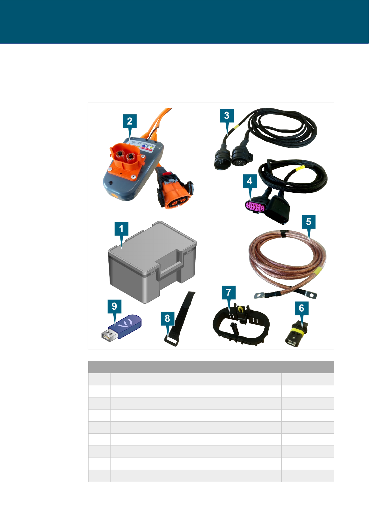
Scope of delivery 8
Design 9
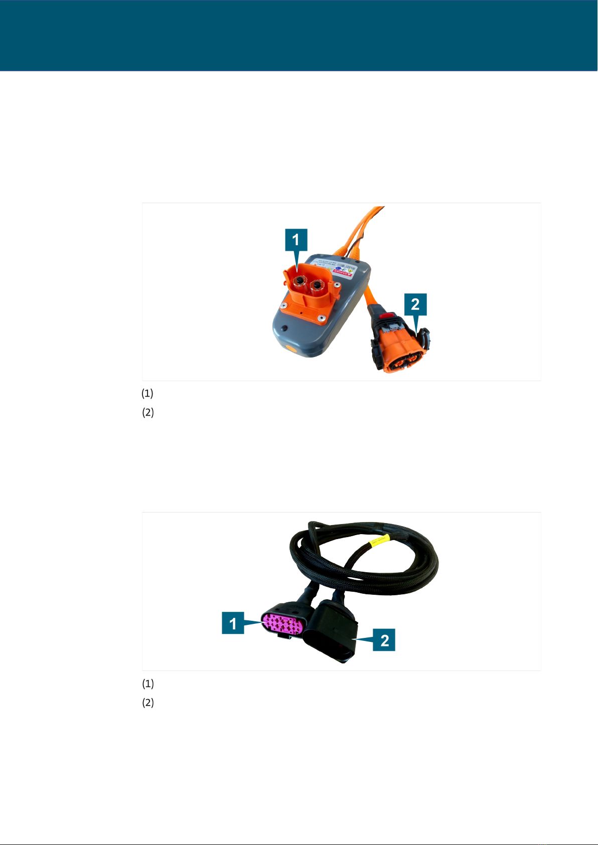
High-voltage test adapter 9
Diagnostic cable, 14-pin 9
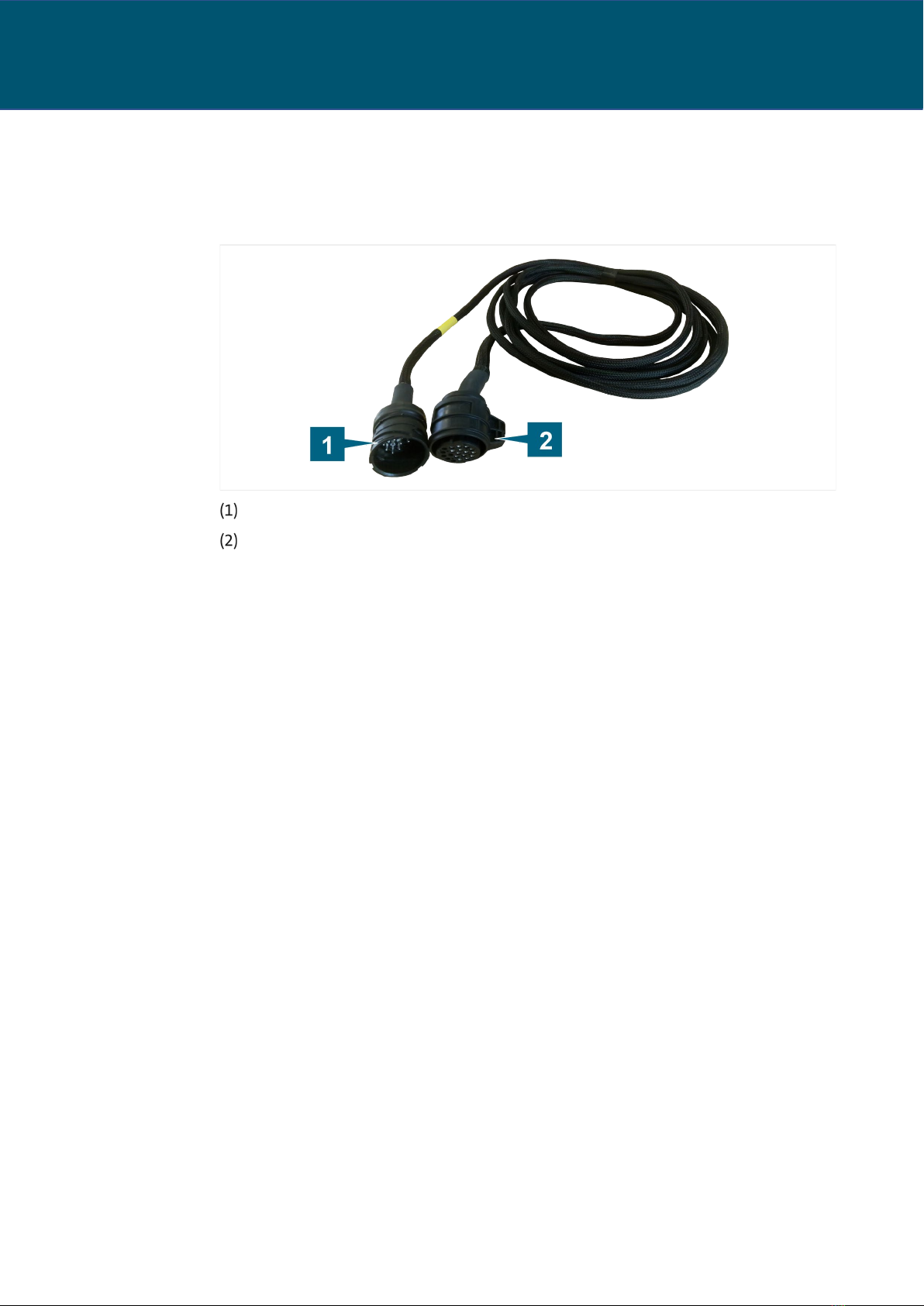
Diagnostic cable, 21-pin 10
Symbols and connections 11
Technical data 12
High-voltage test adapter 12
Diagnostic cable, 14-pin 12
Diagnostic cable, 21-pin 13
Ground cable 13
Ambient conditions 13
Wiring diagram 14
High-voltage test adapter 14
Diagnostic cable, 14-pin 14
Diagnostic cable, 21-pin 15
Ground cable 15
Bypass plug 15
OPERATION 16
Startup 17
Connect ground cable 18
Connect diagnostic cable 19
Bypassing the pilot lines 20
Connect high-voltage test adapter 21
Secure cables with Velcro strap 22
Detaching the plug connections 23
Detaching the high-voltage plug connection 23
Detaching the plug connection on the diagnostic cable (21-pin) 24
Detaching the plug connection on the diagnostic cable (14-pin) 24
Cleaning 25
Disposal 25
Maintenance 25
HELP 26
Warranty 26
Customer service 26

32.VW.2210.1599_BA_V00_EN
VAS 671 001
4
EN | Introduction
Introduction
Preliminary information
Read through this operating manual carefully before using the product.
The product is delivered with a USB stick containing the operating manual in various
languages. You can find the current version and additional languages on our homepage.
The operating manual is an essential part of the product and must be kept together with the
product. If you sell or transfer ownership of the product, the operating manual must be
handed over to the new operator.
In addition to this operating manual, you must observe all relevant regulations for
diagnostics or troubleshooting of intrinsically safe high-voltage systems in road vehicles. This
includes but is not limited to: instructions for the vehicle manufacturer’s diagnostics
systems, company-specific safety requirements and the state of the art for working with
high-voltage systems.
Validity of the declaration of conformity
The declaration of conformity applies to the product described in the operating manual. Any
changes, modifications or extensions shall void the declaration of conformity and the risk
assessment.
Manufacturer specifications
CAR-connect GmbH
Since its founding, our company has focused on groundbreaking solutions for
electromobility. CAR
-
connect develops and produces custom solutions for the automotive
industry, repair shops and
special vehicle fleets.
Our core business is developing and producing innovative high
-
voltage charging technology
for electric vehicles. Our portfolio also includes measurement and diagnostic technology for
the entire vehicle and battery analysis equipment
.
With extensive experience in software and hardware development, CAR
-
connect is your
dependable partner at every production stage, from prototyping to series production.
CAR-connect GmbH – Experience, Expertise and Innovation – MADE IN GERMANY

32.VW.2210.1599_BA_V00_EN
VAS 671 001
5
EN | Safety
Safety
This safety chapter provides information about the following:
•The warning levels contained in this operating manual
•Important safety instructions for the product
•Intended use of the product
•Requirements for the target group
This operating manual is only valid for the following product:
Item number
22101599
Designation
Adapter cable set VAS 671 001
Warning levels
This chapter provides information about the warning levels used in this operating manual.
DANGER
Failure to observe the safety instructions WILL result in death or serious injury!
WARNING
Failure to observe with the safety instructions CAN result in death or serious injury!
CAUTION
Failure to observe the safety instructions CAN result in minor physical injury!

32.VW.2210.1599_BA_V00_EN
VAS 671 001
6
EN | Safety
Important safety instructions
This chapter contains the safety instructions that must be observed when handling the
product.
DANGER
Danger of fatal electric shock!
The electrical voltage in other systems is lethal and will cause death by electric shock!
•Do not use the product for measurements on utility power circuits!
•
Never attempt to power other devices with the product!
WARNING
Danger of fatal electric shock!
The electrical voltage in high-voltage systems is lethal and can cause death by electric
shock!
Liquids, condensation and high humidity can cause short circuits!
•Do not let the product come into contact with liquids!
•
Use the product only in dry and enclosed spaces!
WARNING
Danger of fatal electric shock!
The electrical voltage in the product is dangerous and can cause serious injury or death
from electric shock!
Defective and damaged products cannot guarantee protection against electrical voltage!
•Do not let the product come into contact with chemicals!
•Replace a defective or damaged product immediately!
•
Never attempt to repair or tamper with the product!

32.VW.2210.1599_BA_V00_EN
VAS 671 001
7
EN | Safety
Intended use
The product is used to perform diagnostics on uninstalled high-voltage battery systems. The
product enables you to connect the high-voltage cables, communication cables and pilot line
of the uninstalled traction battery to the electric vehicle. The product is to be used exclusively
for the “Drive ready” functional test.
The product is compatible with the following vehicle models:
•Volkswagen e-Up!
•Volkswagen e-Golf
•Volkswagen Golf GTE
•Volkswagen XL1
•Volkswagen Passat GTE
The product is not used to test that the circuit is de-energized.
Use only the plug connections on the vehicle that the manufacturer has specified in the
guided fault finding.
In this operating manual, vehicle manufacturers are exclusively defined as vehicle
manufacturers in the Volkswagen Group.
Any use beyond what is listed here is prohibited.
Requirements for the target group
Only qualified personnel may work with this product!
In this operating manual, qualified personnel is defined as personnel meeting the
requirements prescribed by the vehicle manufacturer for the Guided Fault Finding in the
respective country of operation.

32.VW.2210.1599_BA_V00_EN
VAS 671 001
8
EN | Product description
Product description
Scope of delivery
Immediately check the condition of the product and the completeness of the delivery. If
anything is missing or defective, please contact the manufacturer immediately.
Item
Designation
VAS no.
(1)
Carrying case
VAS 671001/8
(2)
High-voltage test adapter
VAS 671001/1
(3)
Diagnostic cable, 21-pin (for Volkswagen e-Golf)
VAS 671001/3
(4)
Diagnostic cable, 14-pin (for Volkswagen e-Up!)
VAS 671001/2
(5)
Ground cable
VAS 671001/4
(6)
Pilot line bypass plug for Volkswagen e-Up!
VAS 671004/5
(7)
Pilot line bypass plug for Volkswagen e-Golf
VAS 671001/6
(8)
Velcro strap
VAS 671001/7
(9)
USB stick with operating manual

32.VW.2210.1599_BA_V00_EN
VAS 671 001
9
EN | Product description
Design
High-voltage test adapter
VAS 671001/0
Product design:
Plug
Socket
Diagnostic cable, 14-pin
VAS671001/2
Product design:
Plug, 14-pin
Socket, 14-pin

32.VW.2210.1599_BA_V00_EN
VAS 671 001
10
EN | Product description
Diagnostic cable, 21-pin
VAS 671001/3
Product design:
Plug, 21-pin
Socket, 21-pin

32.VW.2210.1599_BA_V00_EN
VAS 671 001
11
EN | Product description
Symbols and connections
The following symbols are shown on the high-voltage test adapter:
Symbol Meaning
General warning symbols
Electrical hazard!
Read the operating manual!
Serial number of the product
Manufacturer part number
Protection class II
Disposal instruction
Mark of conformity
Vehicle manufacturer’s certification mark
cMETus certification mark
Measurement category according to IEC 61010-31

32.VW.2210.1599_BA_V00_EN
VAS 671 001
12
EN | Product description
Technical data
High-voltage test adapter
VAS 671001/1
Rated data Values
Manufacturer number
22102050
Maximum rated voltage
DC 1000 V
Maximum rated current
50 A
Protection class
II / double insulated
Weight
~ 4510 g
Dimensions L/H/W
~ 180 mm/125 mm/50 mm
Cable length
5000 mm
Diagnostic cable, 14-pin
VAS 671001/2
Rated data Values
Manufacturer number
22102051
Maximum rated voltage
DC 48 V
Maximum rated current
5 A
Protection class
II / double insulated
Weight
~ 500 g
Cable length
5000 mm

32.VW.2210.1599_BA_V00_EN
VAS 671 001
13
EN | Product description
Diagnostic cable, 21-pin
VAS 671001/3
Rated data Values
Manufacturer number
22102225
Maximum rated voltage
DC 48 V
Maximum rated current
5 A
Protection class II / double insulated
Weight
~ 470 g
Cable length
5000 mm
Ground cable
VAS 671001/4
Rated data Values
Manufacturer number
22102224
Maximum rated
voltage
DC 1000 V
Maximum rated
current
50 A
Protection class
II / double insulated
Weight
~ 1460 g
Cable length
5000 mm
Ambient conditions
Ambient conditions Operation Storage Transportation
Temperature
5 °C to 40 °C
-20 °C to 60 °C
-20 °C to 60 °C
Humidity
Max. 80% up to 31° C, decreasing linearly to 50% at 40° C.
Condensation not permitted. Maximum permissible relative
humidity: 60% in environments with corrosive gas/air.

32.VW.2210.1599_BA_V00_EN
VAS 671 001
14
EN | Product description
Wiring diagram
High-voltage test adapter
VAS 671001/1
Diagnostic cable, 14-pin
VAS 671001/2

32.VW.2210.1599_BA_V00_EN
VAS 671 001
15
EN | Product description
Diagnostic cable, 21-pin
VAS 671001/3
Ground cable
VAS 671001/4
Bypass plug
VAS 671001/5, VAS 671001/6
The wiring diagram is identical for all bypass plugs.
12
4
1
3
6
10
15
18 19 20
2
5
9
14
17
8
13
16
11
7

32.VW.2210.1599_BA_V00_EN
VAS 671 001
16
EN | Operation
Operation
This chapter provides information about the following activities:
•Startup
•Detaching the plug connection
•Cleaning
•Disposal
•Maintenance
WARNING
Danger of fatal electric shock!
The electrical voltage in high-voltage systems is lethal and can cause death by electric
shock!
•
Use the product only for the applications intended by the vehicle manufacturer!
CAUTION
Risk of damage!
Plug connections lock into place when attached.
•Unlock the plug connections before you detach them! (See chapter “Detaching the plug
connections”)

32.VW.2210.1599_BA_V00_EN
VAS 671 001
17
EN | Operation
Startup
This section explains the sequence in which you must connect the product’s components to
the high-voltage battery and to the vehicle.
The illustration below shows only the procedure and is suitable for all cases.
Connect the components in the following order:
1. Connect ground cable
2. Connect diagnostic cable
3. Bypass pilot lines
4. Connect high-voltage test adapter
5. Secure cables with Velcro strap

32.VW.2210.1599_BA_V00_EN
VAS 671 001
18
EN | Operation
Connect ground cable
1. Observe the safety instructions.
2. Connect the ground cable to the traction battery at the point specified in the guided fault
finding. Observe the screw tightening torques specified by the vehicle manufacturer.
3. Connect the ground cable to the vehicle body at the point specified in the guided fault
finding. Observe the screw tightening torques specified by the vehicle manufacturer.
You can now connect the diagnostic cable.

32.VW.2210.1599_BA_V00_EN
VAS 671 001
19
EN | Operation
Connect diagnostic cable
Depending on the vehicle to be connected, you must connect the 14-pin or 21-pin diagnostic
cable.
Diagnostic cable (14-pin)
1. Connect the socket of the diagnostic cable to the plug of the traction battery’s battery
management system.
2. Connect the plug of the diagnostic cable to the socket on the vehicle.
3. Make sure that the plug connections audibly click to indicate they are locked.
You can now bypass the pilot line.
Diagnostic cable (21-pin)
1. Connect the socket of the diagnostic cable to the plug of the traction battery’s battery
management system.
2. Connect the plug of the diagnostic cable to the socket on the vehicle.
3. Lock the plug connection by twisting the socket housing.
You can now bypass the pilot line.

32.VW.2210.1599_BA_V00_EN
VAS 671 001
20
EN | Operation
Bypassing the pilot lines
DANGER
Danger of fatal electric shock!
Risk of explosion due to electric arcs!
When the vehicle-side and battery-side pilot lines are bypassed, the safety relay in the
high-voltage battery can sometimes remain closed even when the high-voltage cables
are disconnected! Arcs can occur when disconnecting the cables!
•Never bypass the vehicle-side pilot line and the battery-side pilot line at the same
time!
•Never disconnect the high-voltage cables on vehicles that have not been properly de-
energized!
Depending on the vehicle you are testing, different bypass plugs will be used for the pilot
line.
1. Insert the bypass plug into the high-voltage plug of the connection to be bypassed
(vehicle model: Volkswagen e-Up!).
2. Insert the bypass plug into the high-voltage socket of the connection to be bypassed
(vehicle model: Volkswagen e-Golf). Make sure that the bypass plug is correctly aligned
when inserting it.
The pilot line is now bypassed.
You can now connect the high-voltage test adapter.
This manual suits for next models
1
Table of contents
Other CAR-connect Automobile Accessories manuals
Popular Automobile Accessories manuals by other brands

MobileVision
MobileVision MobileVision BT-HFKP5 Operation and installation manual

Fortin
Fortin EVO ALL Addendum - Suggested Wiring Configuration

Kia
Kia D4211ADE00AL installation instructions

SuperATV
SuperATV DOOR-CA-DEF-MAX-R installation instructions

ACV
ACV 381210-16-1 installation manual

Jaeger
Jaeger 21260514J Fitting instructions

Graber
Graber 180z Assembly instructions

travall
travall TDG 1238D FITTING INSTRUCTION

Camcar
Camcar 40010 AL quick start guide

Whispbar
Whispbar K556W Fitting instructions

Federal Signal Corporation
Federal Signal Corporation Vista Installation and maintenance instructions

Accel
Accel ULTRA OPTI-SPARK II installation instructions