Version 26.02.2018 HW25 (V92) CI-VL2-N902
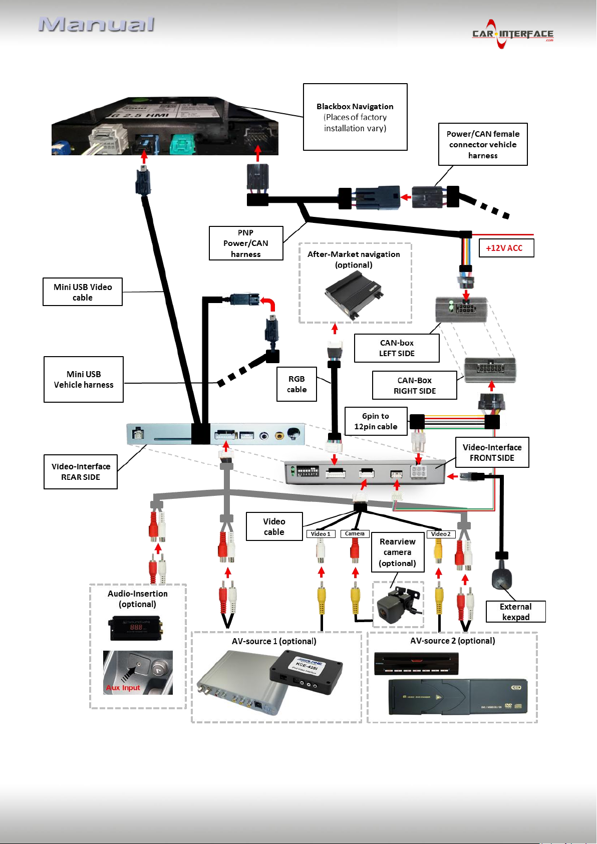
1.3.2.3. RGB-video input signal selection for after-market navigation (Dip 4)
If after-market RGB navigation or other RGB video source is connected, the source’s RGB
output signal must match the interface’s RGB video input setting.
1.3.2.4. Rear-view camera setting (dip 5)
If set to OFF, the interface switches to factory LVDS picture while the reverse gear is engaged
to display factory rear-view camera or factory optical park system picture.
If set to ON, the interface switches to its rear-view camera input while the reverse gear is
engaged.
1.3.2.5. Monitor selection (dips 6-8)
Dips 6-8 are for monitor-specific video settings which cannot be predicted as even within the
same head-unit version, the monitor specifications may vary. It is necessary to try all
possible combinations - while a working video source is connected to the chosen input of the
interface - to see which combination gives the best picture quality and size (some may give
no picture). It is possible to first hot plug through the dip combinations, but if you do not
experience any change of picture after trying all options, retry and disconnected the 6pin
power plug of the video-box between every change of the dip setting.
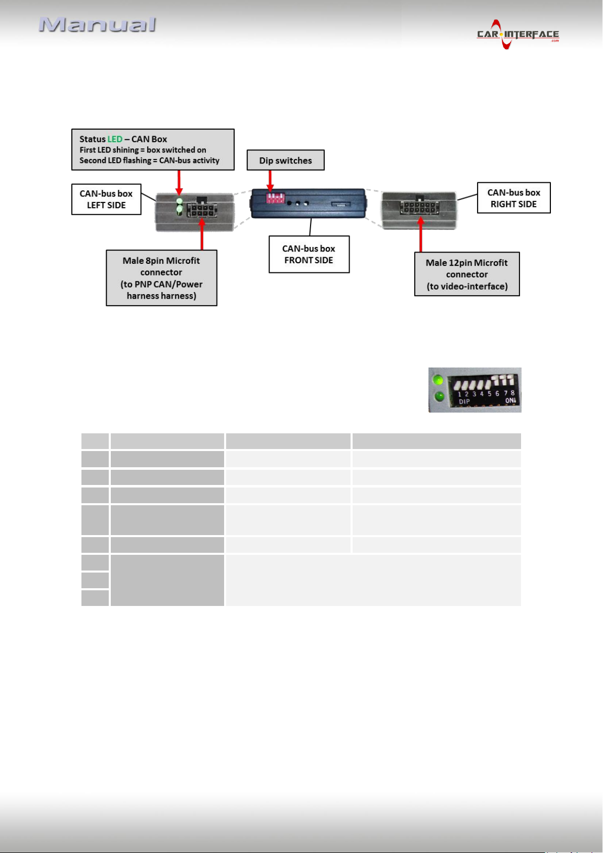
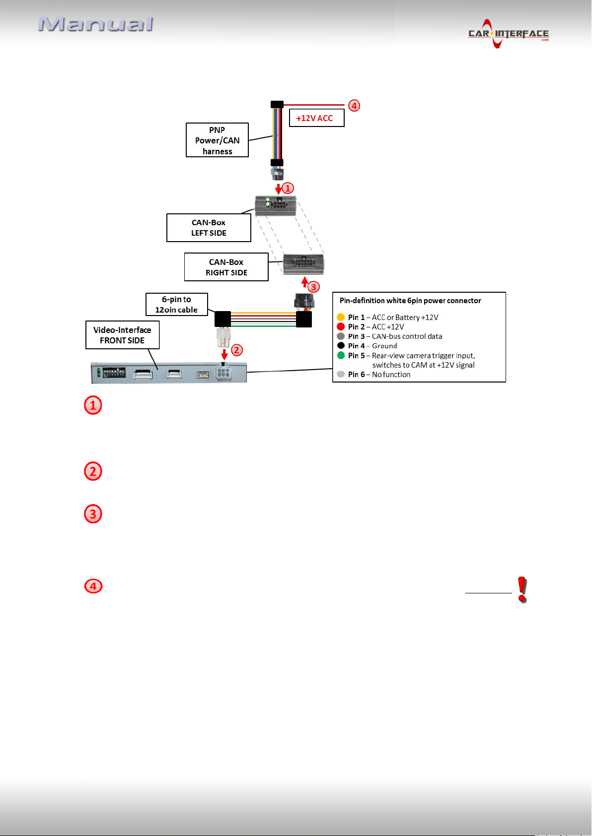
1.4. Dip-switch settings of the CAN-box
By using the Dip-switches the factory Head-Unit or vehicle can be
chosen, the interface will be connected to.
Dip position down is ON and position up is OFF.
After each Dip-switch-change a power-reset of the Can-box has to be performed!