34
Funktion
Function
Lieferumfang
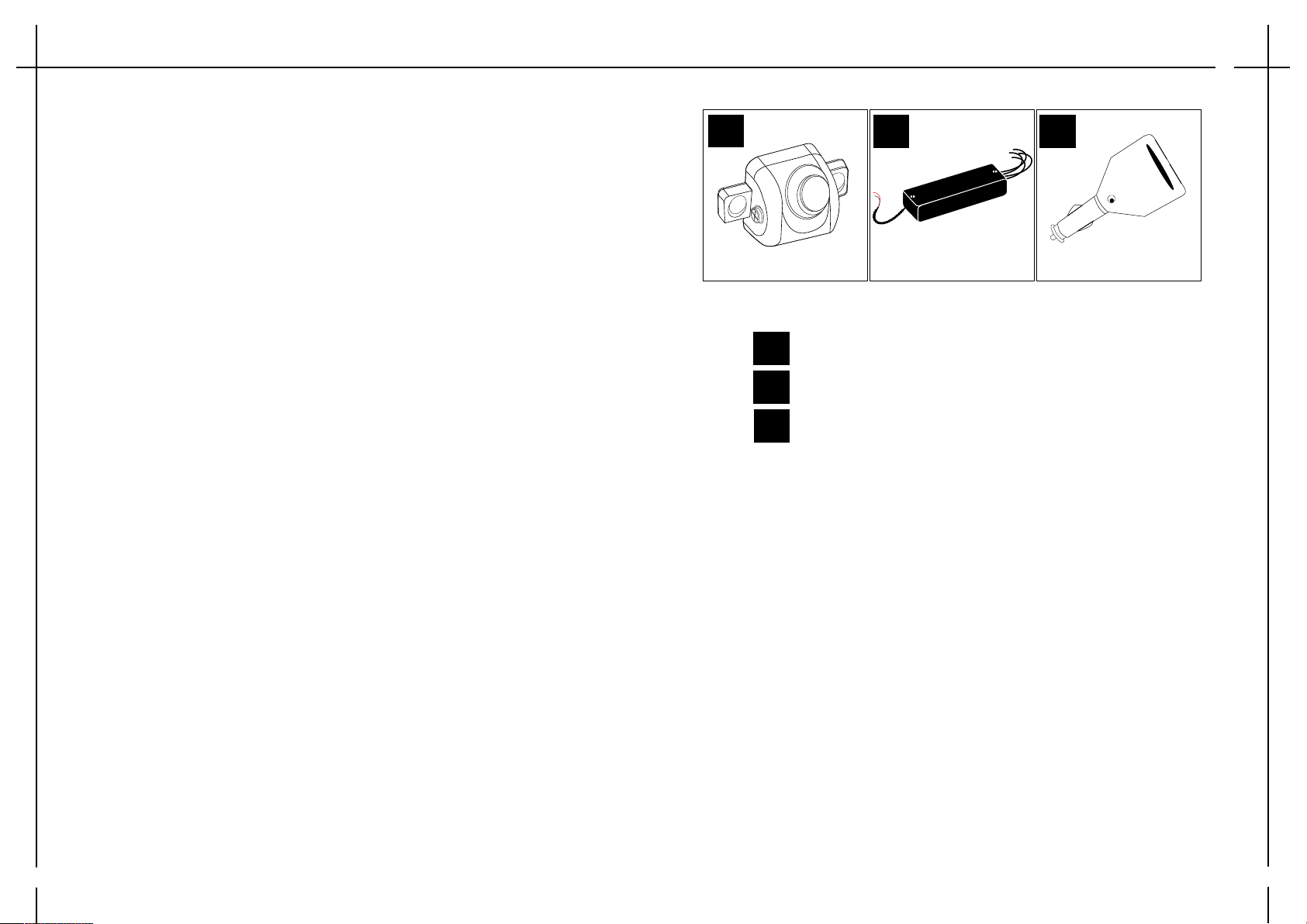
Delivery content
1
Anzahl/ quantity
2 3
Anzahl/ quantity 1
Anzahl/ quantity
Sensoren inkl. Halterung / sensor with holder
Anschlussbox/ connecting box
Easy Key
2
1
3
TX
Powerline
10.5 - 16V
Program opt.
R1. Sensor
R2. Sensor
L1. Sensor
L2. Sensor
Das Bus-Easy-2 System wird einfach an das Rücklicht Ihres Anhängers oder Ihres Fahrradträgers
angeschlossen. Dadurch haben Sie den Vorteil, dass die Rückfahrsensoren automatisch aktiviert werden,
sobald Sie im Fahrzeug den Rückwärtsgang einlegen. Sofern sich Ihr Anhänger dann einem Hindernis
nähert, erkennen die 2 Sensoren die Gefahr und der Easy-Key gibt im Inneren des Fahrzeugs einen gut
hörbaren Alarmton von sich, der auch von Hörgeräteträgern gut gehört werden kann. Das System ist bei
Tag und Nacht funktionstüchtig und hilft Ihnen somit, Ihren Anhänger/ Fahrradträger sicher und schnell
einzuparken, sowie Kratzer und Beulen effektiv zu vermeiden. Dank der störungsfreien CanBus-Technologie
ist das System besonders schnell und einfach zu installieren. Das Besondere an diesem System ist der
Easy-Key, sofern Sie das System einmal fest an Ihrem Anhänger/ Fahrradträger installiert haben, können Sie
das Zugfahrzeug beliebig oft wechseln.
Warnhinweis !
Der Fahrer ist stets dafür verantwortlich das Fahrzeug, sowie Anhänger verkehrssicher zu fahren und die
gelten Gesetze und Vorschriften einzuhalten. Das System entlastet nicht von der eigenen Verantwortung
die Verkehrssituation richtig einzuschätzen und die Fahrweise wie auch die Geschwindigkeit den
Gegebenheiten anzupassen. Das Fahrzeug ist stets nur mit einem an die Geschwindigkeit angepassten
Sicherheitsabstand zu bewegen. Dieses System ist nur ein Hilfsmittel und auf Grund von Systemgrenzen
kann dieses nicht in allen Verkehrssituationen angemessen reagieren. Durch hohe Geschwindigkeit kann es
auf Grund physikalischer Gegebenheiten zu einer verspäteten Warnung kommen. Äußere Einflüsse wie z.B.
starker Regen, Schneetreiben oder auch Verunreinigungen können das System beeinflussen. Es besteht
Unfallgefahr und die Gefahr von Personenschaden oder Sachschaden.
Um die volle Funktionsfähigkeit sicherzustellen:
- Sensoren nicht abdecken, z.B: durch Aufkleber
- Sensoren sauber und eisfrei halten
- Sensoren von Schnee frei halten
Grenzen des Systems: Sehr niedrige Hindernisse sowie höher liegende oder hervorstehende Objekte
außerhalb des Erfassungsbereiches können vom System nicht erfasst werden. Sehr dünne Gegenstände wie
z.B. Bänder oder Drähte können von den Sensoren nicht erkannt werden.
Bei Unsicherheiten bezüglich der richtigen Montage/ Installation raten wir Ihnen eine Fachwerkstatt in Ihrer
Nähe aufzusuchen.
The Bus-Easy-2 system is simply connected to the backight of your trailer or bicycle carrier. This gives you
the advantage of automatically activating the parking system as soon as you reverse the vehicle. If your
vehicle approaches an obstacle, the two sensors detect the danger and the Easy-Key gives a good audible
alarm sound inside the vehicle, which can also be heard by hearing aid wearers. The system is working day
and night, thus helping you to safely and quickly anchor your trailer / bike carrier, as well as effectively
prevent scratches and bumps. Thanks to the interference-free CanBus technology, the system is
particularly fast and easy to install. The special feature of this system is the Easy-Key, once you have
installed the system firmly on your trailer / bike carrier, you can change the towing vehicle as often as you
like.
Warning!
The driver is always responsible for driving the vehicle, as well as trailer driving safety and the applicable
laws and regulations. The system does not relieve the driver of his or her own responsibility of correctly
assessing the traffic situation and adapting the driving mode as well as the speed to the conditions. The
vehicle must always be moved with a safety clearance adapted to the speed. This system is only a tool and
due to system limitations it can not react appropriately in all traffic situations. Due to high speed, a delayed
warning can occur due to physical conditions. External influences such as e.g. Heavy rain, snow drifts or
even impurities can affect the system. There is an accident risk and the risk of personal injury or property
damage.
To ensure full functionality:
- Do not cover the sensors, eg by stickers
- Keep sensors clean and free of ice
- Keep sensors free from snow
Limitations of the system: The system can not detect very low obstacles as well as higher or protruding
objects outside the detection range. Very thin articles, e.g. Tapes or wires can not be detected by the
sensors. In case of uncertaintl regarding correct assembly/ installation, we advise you to visit a specialist
workshop near you.


