Carbon Heater DeskClimate User manual

T i s c h K l i m a
|
D e s k C l i m a t e
Montage- und Bedienungsanleitung
Assembly and operating instructions
TD DeskClimate 230V 620W (TischKlima | DeskClimate)
TD TouchControl 230V 2x2A (Steuerung | Control Unit)

2
DE - Inhalt
Allgemeine Hinweise uSeite 3
Lieferumfang Ihres TischKlima
Gerätes mit Montagezubehör
uSeite 4
Montageanleitung uSeite 5 - 10
Bedienungsanleitung uSeite 11 - 12
Daten und Informationen uSeite 13
EN - Content
General notes uPage 14
Scope of delivery of your DeskClimate
appliance with assembly accessories
uPage 15
Assembly instructions uPage 16 - 21
Operating instructions uPage 22 - 23
Data and information uPage 24

3
Allgemeine Hinweise
Kinder jünger als 3 Jahre sind fernzuhalten, es sein denn, sie werden ständig überwacht.
Kinder jünger als 8 Jahre dürfen das Gerät nur ein- und ausschalten, wenn sie beaufsichtigt werden oder bezüglich des
sicheren Gebrauchs des Gerätes unterwiesen wurden und die daraus resultierenden Gefahren verstanden haben,
vorausgesetzt, dass das Gerät in seiner normalen Gebrauchslage platziert oder installiert ist. Kinder jünger als 8 Jahre dürfen
nicht den Stecker in die Steckdose stecken, das Gerät nicht regulieren, das Gerät nicht reinigen und/oder nicht die Wartung
durchführen.
Das Gerät kann von Kindern ab 8 Jahren und älter, sowie Personen mit verringerten physischen, sensorischen und
mentalen Fähigkeiten oder Mangel an Erfahrung und Wissen benutzt werden, wenn sie beaufsichtigt oder bezüglich des
sicheren Gebrauchs des Gerätes unterwiesen wurden und die daraus resultierenden Gefahren verstehen. Kinder dürfen nicht
mit dem Gerät spielen. Eine Reinigung des Gerätes darf nicht von Kindern ohne Beaufsichtigung durchgeführt werden. Das
Gerät beinhaltet keine zu wartenden Teile.
Vorsicht - Einige Teile des Gerätes können sehr heiß werden und Verbrennungen verursachen. Besondere Vorsicht
ist geboten, wenn Kinder und schutzbedürftige Personen anwesend sind.
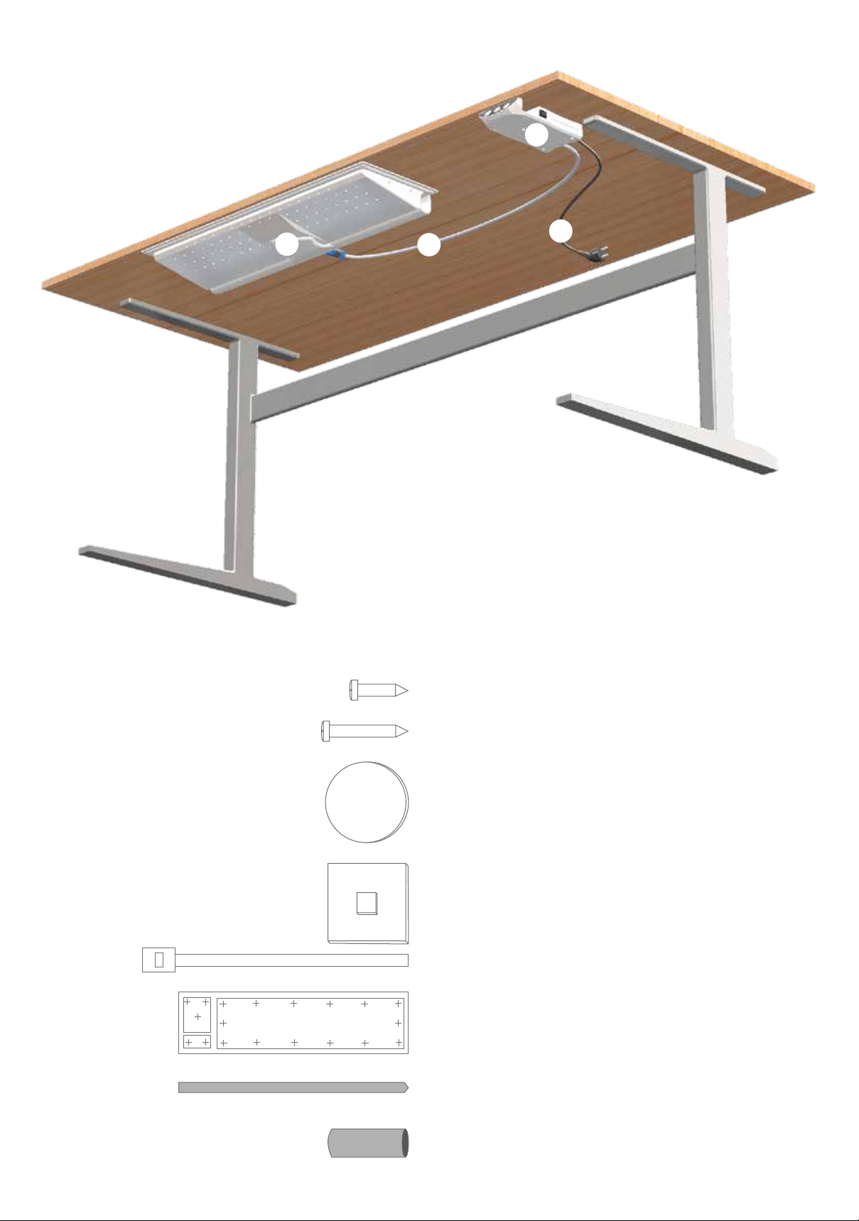
Das Gerät benötigt zur Montage und Betrieb einen Freiraum von mindestens 1000 mm Breite, 300 mm Tiefe und 60 mm
Höhe unter der Tischplatte. Die Dicke der Tischplatte muss mindestens 13 mm betragen (siehe Montageanleitung).
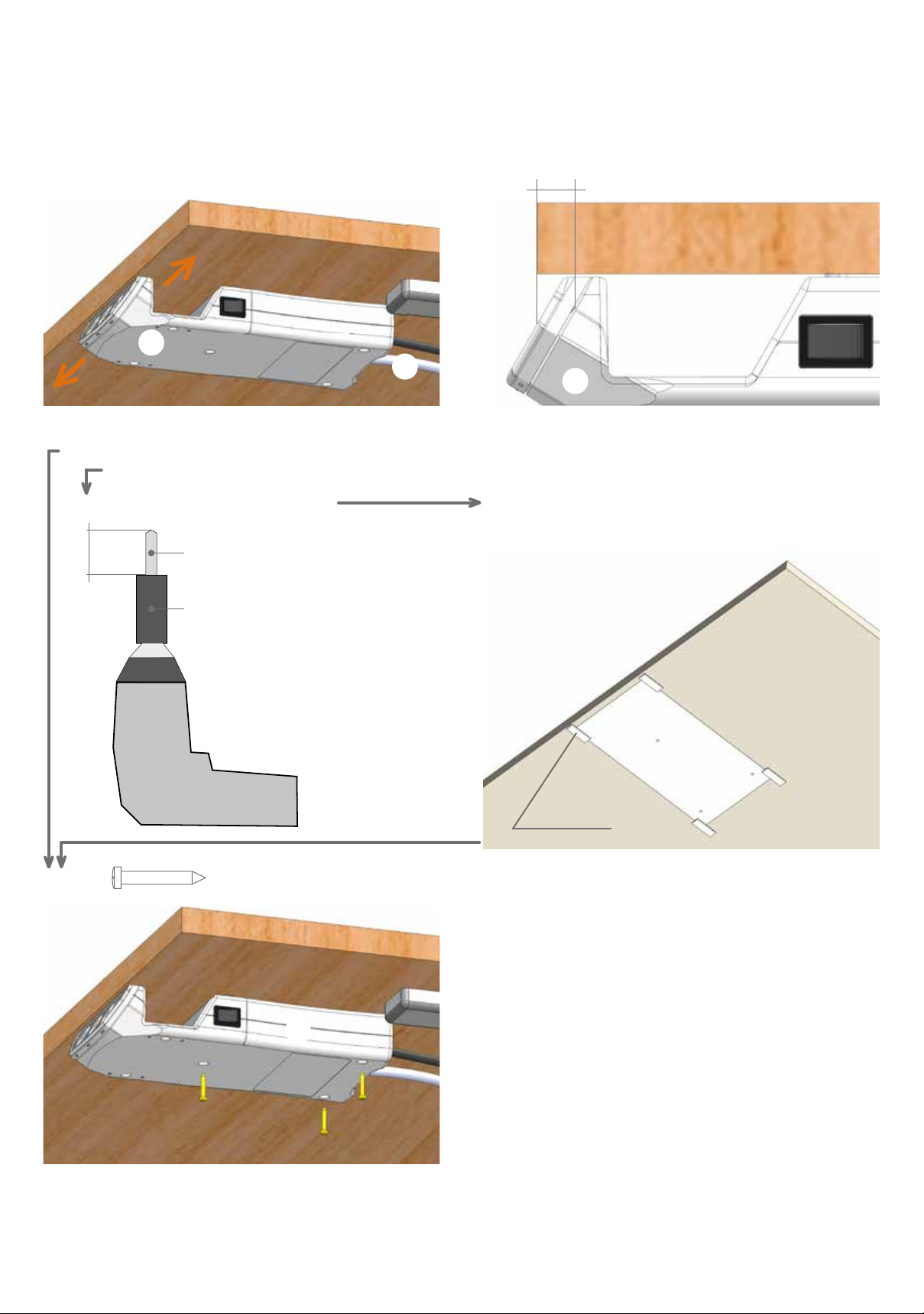
Das TischKlima muss mit Hilfe der beigefügten Schrauben (siehe Montageanleitung) bündig an die Unterseite der
Tischplatte befestigt werden.
Die Öffnungen der Luftansaugkanäle (li. u. re. des TischKlima) müssen einen Mindestabstand von 20 mm zu anderen
Anbauteilen (z.B. Tischbeine) aufweisen.
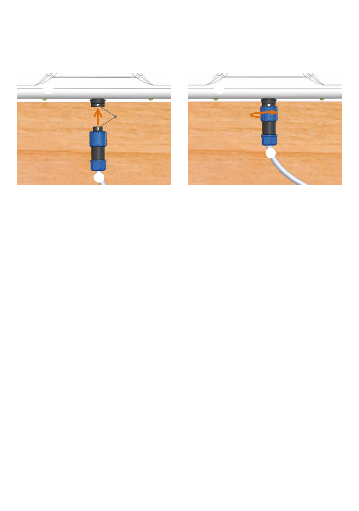
Die Verbindung von TischKlima und TouchControl erfolgt durch das Steuerkabel mit Anschlussstecker. Der Anschluss von
TouchControl an der 230 V/AC Spannungsversorgung erfolgt durch das Netzkabel mit Netzstecker.
Der Netzstecker muss an einer Steckdose angeschlossen sein, die jederzeit zugänglich ist, um das Gerät vollständig vom
Netz trennen zu können.
Bei Höhenverstellbaren Tischen ist darauf zu achten, dass die Kabel bei betätigen der Höhenverstellung nicht eingeklemmt
werden können.
Wenn das Netzkabel und/oder das Steuerkabel beschädigt wird, muss dieses durch den Hersteller oder seinen
Kundendienst ersetzt werden, um Gefährdungen zu vermeiden.
Die Befestigung der Geräte ist mit den dazu gelieferten Schrauben (siehe Montageanleitung) oder identischen Schrauben
vorzunehmen.

4
Lieferumfang
TischKlima
Steuerung
Steuerkabel
Netzkabel
Montagezubehör
(a) 14 x Schraube Gewinde 3,0 mm, Länge 12,0 mm
nur für Befestigung von TischKlima
(b) 3 x Schraube Gewinde 2,9 mm, Länge 19,0 mm
nur für Befestigung von Steuerung
(c) 4 x Klebepunkte 20,0 mm
Alternative für (b) Befestigung von Steuerung
(d) 2 x Kabelbindersockel selbstklebend
(e) 2 x Kabelbinder
für Befestigung von Kabel +unter der Tischplatte
(f) 1 x Bohrschablone
nur für Vorbohren in
Kunststofftischplatte und/oder Querstrebe
(g) 1 x Bohrer D 2,5 mm
nur für Vorbohren in
Kunststofftischplatte und/oder Querstrebe
(h) 1 x Distzanzhülse 20,0 mm
für Einstellen der Bohrtife auf 10,0 / 14,0 mm

5
Montageanleitung
zwei Personen erforderlich
Schritt 1
Befestigung TischKlima unter der Tischplatte
1. Wichtig! Dicke der Tischplatte nachmessen.
Erforderliches Mindestmaß 13,0 mm, damit Tischplatte durch Schrauben nicht beschädigt wird!
2. Position TischKlima bestimmen
Mittig zur Sitzposition und ca. 5,0 mm hinter der Tischkante bzw. der Querstrebe (siehe auch Bilder unter 4.)
Tischkante
Querstrebe
3. Wichtig! Entscheiden ob vorgebohrt werden muss.
Bei Holztischplatten NICHT vorbohren! Direkt weiter mit Pukt 4.
NUR bei harter Kunststofftischplatte vorbohren! Weiter mit Punkt 3.1. bis 4.
3.1. Einstellung Bohrtiefe auf 10 mm
10 mm (g) Bohrer D 2,5 mm
(h) Distanzhülse 20 mm
über Bohrer stecken und
Bohrer so befestigen, dass
dieser noch 10 mm herausschaut
Akkuschrauber
Bohrmaschine
3.2. (f) Bohrschablone auf Position kleben
3.3. Durch Fadenkreuze #der Bohrschablone 14-mal je
10 mm tief in die Kunststofftischplatte
vorbohren
3.4. (f) Bohrschablone wieder
entfernen
#
#
#
#
#
#
#
#
#
#
#
#
#
#
(f) Bohrschablone
Klebestreifen nicht im
Lieferumfang enthalten
4. Mit (a) 14-mal Schraube Gewinde 3,0 mm und Länge 12 mm
TischKlima anschrauben bis Aluminiumplatte vollächig an der Tischplatte anliegt
Tischplatte ohne Querstrebe
Tischplatte mit Querstrebe

6
Schritt 2
Steuerkabel mit TischKlima verbinden
Wichtig! Die Montageposition der Steuerung ist abhängig von dessen Steuerkabel.
Daher zuerst das Steuerkabel an TischKlima anschließen und anschließend Position der Steuerung festlegen.
1. Stecker verbinden. Markierungspunkte beachten. 2. Stecker verschrauben.
Markierungspunkte
Schritt 3
Befestigung von Steuerung unter der Tischplatte
Information
Steuerung an Tischplatte kleben
wird empfohlen oder
usiehe Variante 1 - Seite 7
Steuerung an Tischplatte schrauben usiehe Variante 2 - Seite 8
Steuerung an Querstrebe schrauben
falls eine solche vorhanden
usiehe Variante 3 - Seite 9

7
Variante 1 uan Tischplatte kleben
1. Klebeäche auf Steuerung mit trockenem Tuch gut reinigen (kein Hashaltsreinigungsmittel verwenden), danach 4-mal
(c) Klebepunkte einseitig ablösen und auf Steuerung ankleben.
(c)
(c)
(c)
(c)
2. Klebeposition der Steuerung ca. 5 bis 10 mm hinter der Tischkante bestimmen und dabei die Länge des
Steuerkabels berücksichtigen. 5 -10 mm
3. Fläche für Klebeposition unter der Tischplatte mit trockenem Tuch bzw. mit Spiritus/Alkohol gut reinigen
(kein Hashaltsreinigungsmittel verwenden) und mind. 3 Minuten abtrocknen lassen.
4. Schutzfolie von (c) Klebepunkten entfernen, Steuerung an Tischplatte ankleben und mind. 20 Sekunden fest
andrücken. Wichtig! Die Steuerung kann nur durch eine Drehbewegung wieder abgelöst werden (ein Abziehen nach
unten ist nicht möglich, siehe Bild).

8
Variante 2 uan Tischplatte schrauben
1. Wichtig! Dicke der Tischplatte nachmessen.
Erforderliches Mindestmaß 13,0 mm, damit Tischplatte durch Schrauben nicht beschädigt wird!
2. Montageposition der Steuerung ca. 5 bis 10 mm hinter der Tischkante bestimmen und dabei die Länge des
Steuerkabels berücksichtigen.
5 -10 mm
3. Wichtig! Entscheiden ob vorgebohrt werden muss.
Bei Holztischplatten NICHT vorbohren! Direkt weiter mit Pukt 4.
NUR bei harter Kunststofftischplatte vorbohren! Weiter mit Punkt 3.1. bis 4.
3.1. Einstellung Bohrtiefe auf 10 mm
10 mm (g) Bohrer D 2,5 mm
(h) Distanzhülse 20 mm
über Bohrer stecken und
Bohrer so befestigen, dass
dieser noch 10 mm herausschaut
Akkuschrauber
Bohrmaschine
3.2. (f) Bohrschablone auf Position kleben
3.3. Durch Fadenkreuze #der Bohrschablone 3-mal je
10 mm tief in die Kunststofftischplatte
vorbohren
3.4. (f) Bohrschablone wieder
entfernen
4. Mit (b) 3-mal Schraube Gewinde 2,9 mm und Länge 19 mm Steuerung anschrauben.
#
#
#
(f) Bohrschablone
Klebestreifen nicht im
Lieferumfang enthalten

9
Variante 3 uan Querstrebe schrauben
1. Montageposition der Steuerung bestimmen und dabei die Länge des Steuerkabels berücksichtigen.
2. Befestigungslöcher vorbohren.
2.1. Einstellung Bohrtiefe auf 14 mm
#
(f) Bohrschablone
Klebestreifen nicht im
Lieferumfang enthalten
#
14 mm (g) Bohrer D 2,5 mm
(h) Distanzhülse 20 mm
über Bohrer stecken und
Bohrer so befestigen, dass
dieser noch 14 mm herausschaut
Akkuschrauber
Bohrmaschine
2.2. (f) Bohrschablone auf Position kleben
2.3. Durch Fadenkreuze #der Bohrschablone 2-mal je
14 mm tief in die Querstrebe vorbohren
2.4. (f) Bohrschablone wieder
entfernen
3. Mit (b) 2-mal Schraube Gewinde 2,9 mm und Länge 19 mm Steuerung anschrauben.

10
Schritt 4
Befestigung von Steuerkabel und Netzkabel unter der Tischplatte
1. Mit (d) 2-mal Kabelbindersockel selbstklebend
und (e) 2-mal Kabelbinder
die Kabel unter der Tischplatte xieren.
1. Wichtig!
Bei höhenverstellbaren Tischen darauf achten, dass die Kabel (+ ) nicht eingeklemmt werden können!

Um Kühlmodus manuell Auszuschalten die
Ventilationstaste für 1 Sekunde berühren.
Standby-Modus (betriebsbereit), nach ca. 1 Minute ohne Betätigung,
erlischt die Kreisbeleuchtung um die Symbole.
11
Bedienungsanleitung
Kühlmodus
Ventilationsbetrieb ohne Wärmefunktion
Mit dem Hauptschalter seitlich an der Steuerung
das Gerät Ein- (Standby-Modus) oder Ausschalten.
Standby-Modus (betriebsbereit), nach ca. 1 Minute ohne Betätigung,
erlischt die Kreisbeleuchtung um die Symbole.
Um den Kühlmodus zu Starten, die
Ventilationstaste für 1 Sekunde berühren.
Ventilationsstufen (Intensität von 1=min. bis 5=max.)
durch kurzes Antippen der Ventilationstaste
wählen. 1
23
4
5
Automatische Abschaltung durch kurzes Antippen
der Zeittaste wählen.
Stufe 5 = Abschaltung nach 7,5 h
Stufe 4 = Abschaltung nach 6,0 h
Stufe 3 = Abschaltung nach 4,5 h
Stufe 2 = Abschaltung nach 3,0 h
Stufe 1 = Abschaltung nach 1,5 h
1
23
4
5

12
Wärmemodus
für Tischplatte und Ventilationsbetrieb/Beinheizung
Um den Wärmemodus zu Starten, die
Wärmetaste für 1 Sekunde berühren.
Wärme Tischplatte (Intensität von 1=min. bis 5=max.)
durch kurzes Antippen der Wärmetaste wählen.
Information
Je nach Dicke der Tischplatte, kann es 5 bis 10
Minuten dauern, bis die Tischoberäche warm wird.
1
23
4
5
Warmluft Ventilationsstufen/Beinheizung
(Intensität von 1=min. bis 5=max.) durch kurzes
Antippen der Ventilationstaste wählen.
Information
Für das erste Aufheizen, benötigt der Wärmetauscher
ca. 2 Minuten Zeit, um die gewählte Temperatur-
intensität zu erreichen. In dieser Zeit blinkt die
Anzeige und die Warmluftventilation startet, nachdem
der Wärmetauscher die Betriebstemperatur erreicht
hat.
1
23
4
5
Automatische Abschaltung durch kurzes Antippen
der Zeittaste wählen.
Stufe 5 = Abschaltung nach 7,5 h
Stufe 4 = Abschaltung nach 6,0 h
Stufe 3 = Abschaltung nach 4,5 h
Stufe 2 = Abschaltung nach 3,0 h
Stufe 1 = Abschaltung nach 1,5 h
1
23
4
5
Um Wärmemodus manuell Auszuschalten die
Wärmetaste für 1 Sekunde berühren.
Standby-Modus (betriebsbereit), nach ca. 1 Minute ohne Betätigung,
erlischt die Kreisbeleuchtung um die Symbole.

13
Daten und Informationen
Daten
Netzspannung u220 - 240 Volt
Netzfrequenz u50 - 60 Hertz
Schutzklasse uI (Schutzerde mit Schukonetzstecker)
Nennleistung Tischheizung max. u235 Watt
Nennleistung Beinheizung max. u375 Watt
Nennleistung Lüfter/Kühlen max. u10 Watt
Nennleistung gesamt max. u620 Watt
Nennleistung Standby: u< 0,4 Watt
Energieverbrauch u290 Watt
Mittelwert für Heizen (Tisch und Beine) bei max. Intensität und 20 °C Raumtemperatur
10 Watt
Maximalwert für Lüften/Kühlen (Beine)
Temperaturbereich Tischheizung: u25 - 45 °C (elektronisch geregelt)
Temperaturbereich Beinheizung: u50 - 75 °C (elektronisch geregelt)
Überhitzungsschutz uJa (80 °C Schutzabschaltung)
Elektrische Sicherung uJa
Erdung uJa
Intensität für Lüften und/oder Heizen u5 Leistungsstufen
Automatische Abschaltung u5 Stufen (1,5 - 7,5 h)
Maße TischKlima (Heizung/Lüfter) uB 800 mm x T *250 mm / **320 mm x H 20-60 mm
*ohne Kabelstecker
**mit Kabelstecker
Maße TouchControl (Steuerung) uB 120 mm x T *250 mm / **260 mm x H 35 mm
*ohne Kabelabgang
**mit Kabelabgang
Gesamtgewicht u5,5 kg
Länge Steuerkabel u1,5 m
Länge Netzkabel u1,5 m
Information
Hersteller uCarbon Heater GmbH | Auf Stocken 1 | 78073 Bad Dürrheim | Germany
www.carbon-heater.com
Kennzeichnung u
WEEE-Reg Nr: uDE 32636890
Nicht im Hausmüll entsorgen!

14
General notes
Children under the age of 3 must be kept away unless they are continuously supervised.
Children under the age of 8 may only switch the appliance on and off if they are supervised or have been given instructions
on how to use the appliance in a safe way and understand the hazards involved, provided that the appliance is placed or
installed in its normal operating position. Children under the age of 8 must not plug in, regulate, clean or carry out
maintenance on the appliance.
The appliance may be used by children of 8 years of age and older as well as by persons with reduced physical, sensory and
mental abilities or by those without experience and/or knowledge insofar as they are supervised or have been instructed on
the safe operation of the appliance and have understood the dangers that are associated with its use. Children may not play
with the appliance. Children may not clean the appliance without supervision. The appliance contains no serviceable parts.
Caution - Some parts of the appliance may become very hot and cause burns. Particular attention has to be given to
where children and vulnerable people are present.
The appliance requires clearance of at least 1000 mm in width, 300 mm in depth and 60 mm in height under the table top
for assembly and operation. The thickness of the table top must be at least 13 mm (see assembly instructions).
The DeskClimate must be attached ush to the underside of the table top with the enclosed screws (see assembly
instructions).
The openings of the air intake ducts (left and right of the DeskClimate) must be at least 20 mm from other attachment parts
(e.g., table legs).
DeskClimate and TouchControl are connected by means of the control cable with connector plug. TouchControl is
connected to the 230 V/AC power supply via the mains cable with mains plug.
The mains plug must be connected to an outlet that is accessible at all times to be able to completely disconnect the
appliance from the mains.
For vertically adjustable tables, make sure that the cables cannot be jammed when adjusting the height of the table.
If the mains cable and/or control cable is damaged, it must be replaced by the manufacturer or their service department in
order to avoid hazards.
The appliances must be attached with the supplied screws (see assembly instructions) or identical screws.

15
Package contents
DeskClimate
Control unit
Control cable
Mains cable
Assembly accessories
(a) 14 x screw threads, 3.0 mm, length: 12.0 mm
only for attaching the DeskClimate
(b) 3 x screw threads, 2.9 mm, length: 19.0 mm
only for attaching the control unit
(c) 4 x adhesive points, 20.0 mm
Alternative for (b) attaching the control unit
(d) 2 x cable tie bases, self-adhesive
(e) 2 x cable ties
for xing cables +under the table top
(f) 1 x drilling template
only for pre-drilling in
plastic table tops and/or cross braces
(g) 1 x drill bit, diameter: 2.5 mm
only for pre-drilling in
plastic table tops and/or cross braces
(h) 1 x distance sleeve, 20.0 mm
for adjusting the drilling depth to 10.0/14.0 mm

16
Assembly instructions
2 people required
Step 1
Attaching the DeskClimate under the table top
1. Important! Measure the table top‘s thickness.
The required minimum dimension is 13.0 mm, so that the table top is not damaged by screws!
2. Determine the position of the DeskClimate
Concentrically to your seating position and approx. 5.0 mm behind the edge of the table or the cross brace (see also
images under 4.)
edge of the table
cross brace
3. Important! Decide whether pre-drilling is required or not.
NO pre-drilling with wooden table tops! Go straight to and continue with Point 4.
Pre-drilling ONLY with hard plastic table tops! Continue with Points 3.1. to 4.
3.1. Setting the drilling depth to 10 mm
10 mm (g) Drill bit, diameter: 2.5 mm
(h) Insert the distance sleeve 20 mm
above the drill bit and fasten the
drill bit so that it still protrudes by
10 mm
Screwdriver
Drill
3.2. (f) Glue drilling template to position
3.3. Through crosshairs #dof the drilling template,
pre-drill 14 x 10 mm deep into the plastic
table top
3.4. (f) Remove the drilling
template again
#
#
#
#
#
#
#
#
#
#
#
#
#
#
(f) Drilling template
Adhesive strips not
included in the scope
4. With (a) 14 x 3.0 mm screw threads and 12 mm in length
Screw on the DeskClimate until the aluminium plate is in full contact with the table top
Table top without cross brace
Table top with cross brace
16

17
Step 2
Connect the control cable to the DeskClimate
Important! The assembly position of the Scontrol unit depends on its control cable.
Therefore, rst connect the control cable to the DeskClimate and then set the position of the control unit.
1. Connect the plug. Observe marking points. 2. Screw the plug.
Marking points
Step 3
Attaching the control unit under the table top
Information
Gluing the control unit to the table
top is recommended or
usee Option 1 - Page 18
screwing the control unit to the
table top,
usee Option 2 - Page 19
Screwing the control unit to the
cross brace if one is available
usee Option 3 - Page 20

18
Option 1 uGlue to table top
1. Clean the adhesive surface of the control unit with a dry cloth (do not use a detergent), then remove the 4 (c) adhesive
points on one side and glue them to the control unit.
(c)
(c)
(c)
(c)
2. Determine the gluing position of the control unit approx. 5 to 10 mm behind the table edge, thereby considering the
length of the control cable.5 -10 mm
3. Clean the surface for the adhesive position under the table top well with a dry cloth or with spirit/alcohol
(do not use a detergent) and allow it to dry for at least 3 minutes.
4. Remove the protective lm from (c) the adhesive points, glue the control unit to the table top and press rmly for
at least 20 seconds. Important! The Scontrol unit can only be removed by circular motion (pulling it downwards is not
possible, see image).

19
Option 2 uScrew to table top
1. Important! Measure the table top‘s thickness.
The required minimum dimension is 13.0 mm, so that the table top is not damaged by screws!
2. Determine the assembly position of the control unit approx. 5 to 10 mm behind the table edge, thereby considering
the length of the control cable.
5 -10 mm
3. Important! Decide whether pre-drilling is required or not.
NO pre-drilling with wooden table tops! Go straight to and continue with Point 4.
Pre-drilling ONLY with hard plastic table tops! Continue with Points 3.1. to 4.
3.1. Adjustment of drilling depth to 10 mm
10 mm (g) Drill bit, diameter: 2.5 mm
3.2. (f) Glue drilling template to position
3.3. Through crosshairs #of the drilling template,
pre-drill 3 x 10 mm deep into the
plastic table top
3.4. (f) Remove drilling
template again
4. Using (b) 3 x 2.9 mm screw threads and 19 mm in length, screw on the control unit.
#
#
#
(f) drilling template
Adhesive strips not
included in the scope of delivery
(h) Insert the distance sleeve 20 mm
above the drill bit and fasten the
drill bit so that it still protrudes by
10 mm
Screwdriver
Drill

20
Option 3 uScrew to cross brace
1. Determine the assembly position of the control unit, taking into account the length of the control cable.
2. Pre-drill mounting holes.
2.1. Setting the drilling depth to 14 mm
#
(f) Drilling
template
Adhesive strips not
included in the scope
#
14 mm
(g) Drill bit, diameter: 2.5 mm
(h) Insert the distance sleeve 20 mm
above the drill bit and fasten the
drill bit so that it still protrudes by
14 mm
Screwdriver
Drill
3.2. (f) Glue drilling template to position
3.3. Through crosshairs #of the drilling template,
pre-drill 2 x 14 mm deep into the
cross brace
3.4. (f) Remove drilling
template again
4. Using (b) 2 x 2.9 mm screw threads and 19 mm in length, screw on the control unit.
Table of contents
Languages:
Other Carbon Heater Heater manuals
Popular Heater manuals by other brands

Kohler
Kohler S450 Installation and Homeowners Guide

ThermaQuiet
ThermaQuiet DL65-WM Installation instructions and owner's manual

STIEBEL ELTRON
STIEBEL ELTRON ETW 12 Operation and installation

Vortice
Vortice SCALDATUTTO EVO T Instruction booklet

STIEBEL ELTRON
STIEBEL ELTRON DHC series use and care manual

Smith's Heating First
Smith's Heating First Signature Installation & user guide