9CAUTION Do not close door from
outside until all latches have been
checked for correct setting and
operation. Failure to follow these
instructions carefully may result in a
lock out situation and a chargeable
service call may result.
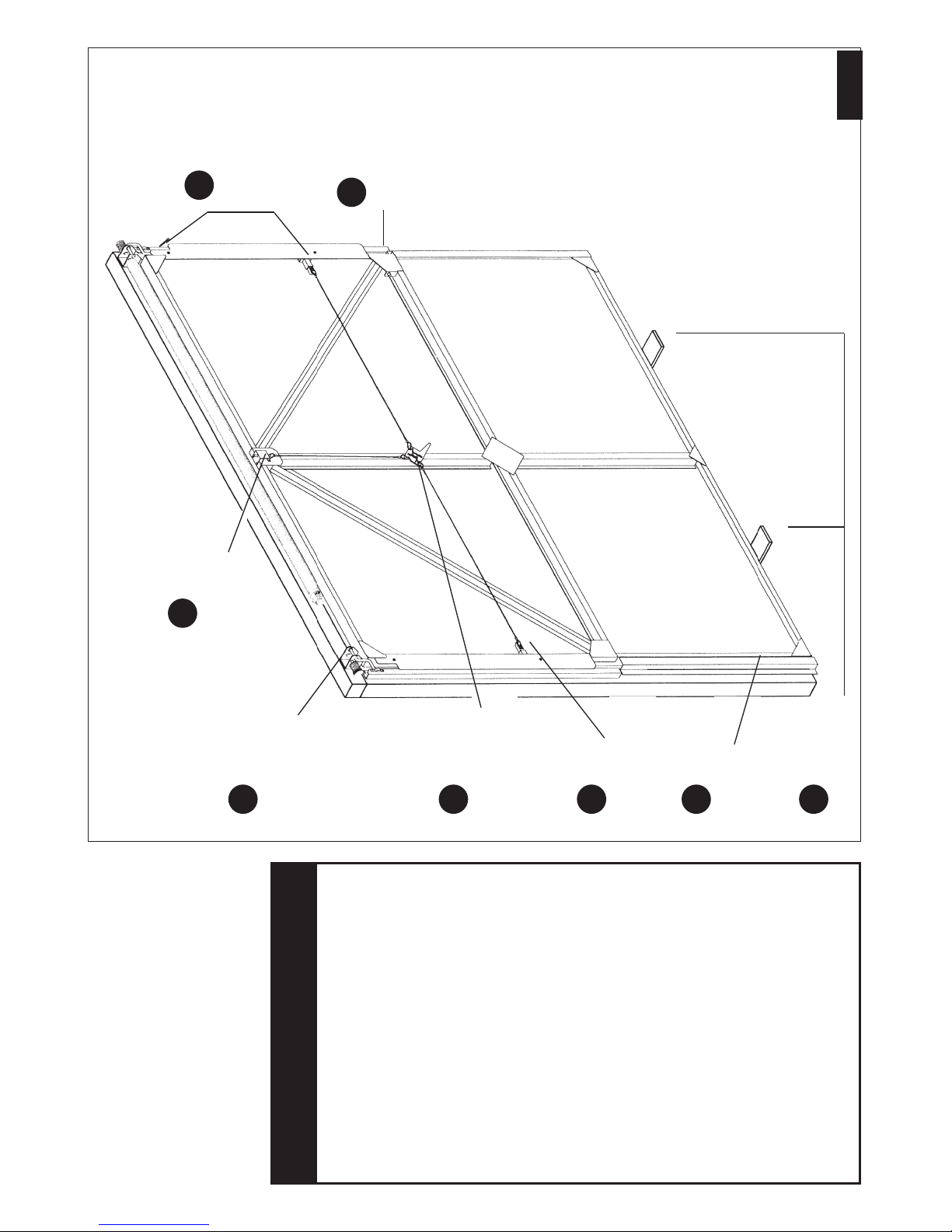
Take cable with double loop and attach
looped end of cable (without clamp) in
centre groove of nylon latch (see fig. 8).
Loop the other end of the cable over the
closest arm on the internal latch lever.
Repeat this operation for both side latches.
Remove ‘Park pins’ to release latches (see fig.
8). The setting mark on the nylon latch (see
fig. 8) indicates nominal latch position but
adjustment may be necessary to ensure
correct latch engagement. This can be done
by either looping the cable over a different
groove in the latch (see fig. 8) or by
loosening the screw on the cable clamp,
moving cable slightly and re-tightening.
IMPORTANT Test latches for correct
operation.
•
Side latches should engage behind side
WARNING
When fitting the multi-point latching do not
shut the door whilst you are outside the
garage until all latches have been correctly
set and tested (See instructions 8 & 9)
Failure to comply could result in being
locked out of the garage and a chargeable
service call will be required.
IMPORTANT NOTES
BEFORE COMMENCING WORK:
aRemove all wrapping including plastic sleeve
from spring. Ensure that your door has been
supplied with the correct main fixing pack
(fixing pack codes are on the identification
label on reverse of door).
Remove lock pack, fixing pack and the black
plastic weather strips from their transit
positions on the rear of the door.
bBefore fitting the door, check opening size and
squareness of the timber frame. The door is
made smaller to give correct clearance within
the frame.
Also check that the existing timber goalpost
frame is securely fitted to the surrounding
brickwork and is structurally sound.
c
There must be a minimum of 65mm (21/2")
headroom above lower face of top timber, or
lintel. This must reach back into the garage for at
least 1300mm (4'3").
dA 70mm ×70mm (23/4") timber ‘goalpost’
frame is recommended but the gear only
requires a fitting clearance of 45mm per side.
eAll the initial work is carried out from inside
the garage so tools and parts should be to hand
before door is placed in the opening.
fSlots are provided in all key components to
allow for final adjustment, when door has
been installed.
SAFETY FIRST Please read instructions right through before
commencing installation.
CAUTION
The spring is under tension – follow instructions carefully
to avoid any chance of personal injury.
▲
!
This garage door has been designed to be as easy as possible to use, service and automate
when installed correctly. Please therefore take time to read these instructions fully before
beginning any work. Note: This door is recommended for fitment to a 70mm ×70mm
timber goalpost frame (not supplied). A separate set of instructions should be used if the
door has been supplied pre-fitted to a quick-fit steel frame.
IMPORTANT INFORMATION
1 This garage door is intended for domestic use only.
2 Garage doors are heavy and may have sharp edges.
Wear protective gloves. Installation should not be undertaken alone.
Care must be taken when handling.
3 Ensure the door is continuously supported before it is secured and
avoid installing in windy conditions.
4 Do not attempt to install or adjust this door if you are unsure of
any of the instructions below.
5 Wear eye protection.
iOn completion of installation lubricate the spring, wheel spindles and all pivot points
with a ‘3 in 1’ type lubricant.
ii Grease top catch pin to ensure smooth operation. (Do not grease side latches).
iii Check that all fasteners are fully tightened.
iv Ensure track runners are clean and door operates smoothly through full open/close cycle.
vIt is the responsibility of the installer to ensure that the spring tension is correctly set.
If the tension requires adjustment, refer to maintenance label on rear of door.
vi Do not paint spring or any moving parts.
NOTES ON COMPLETION
1. Open door and remove the intermediate
1. screws from the side runners, leaving the top
1. and bottom fixings in place.
2. Wearing safety glasses, close door and grip R/H
1. blue pulley with 22mm A/F spanner and by
1. turning upwards, align holes in spring anchor
1. bush and spring shaft. Insert retaining pin (4mm
1. dia. x 50mm split pin or similar) fully into this
1. hole as shown, then remove the spanner. (See
1. Fig. 4)
3. Insert 4 off No. 10 x 1/2” self tapping transit
1. screws through the top side seal to secure the
1. side runners in place. (See Fig.1)
4. Remove lower rubber weatherstrips. (See Fig.1)
5. Remove 4 screws securing the two spring
1. mounting brackets. (See Fig.2)
6. Using cable ties, or strong cord, or similar, tie
1. the spring assembly securely to the door panel.
7. Remove top catch bracket. (See Fig.7)
8. Prop door in position.
9. Remove top and bottom track fixings including
security block.
10. The door can now be carefully removed from
the opening. Seek assistance in lifting.
IN THE EVENT OF DIFFICULTY PLEASE CONTACT YOUR LOCAL GARAGE DOOR SPECIALIST
– SEE YELLOW PAGES FOR DETAILS
Cardale Group Ltd, Brackley, Northants Issue A 9/04 DPIN 045105
FIG 8 FIG 9
FIG 10
Nylon latch
Park pin
Setting
mark
Cable clamp
and screw
Latch lever
No. 8 ×1"
self tapping
screws
Side timber
Black plastic
weather strip
DOOR
Outside
Inside garage
Weather
beading
19 ×19
Head Timber
Door
18 REF
INSTALLATION INSTRUCTIONSDISMANTLING INSTRUCTIONS
Trackless Door Gear
THESE INSTRUCTIONS MUST BE FOLLOWED CAREFULLY
GARAGE DOORS ARE HEAVY AND AWKWARD TO HANDLE. ENSURE
ASSISTANCE IS AVAILABLE AND THAT SAFETY GLOVES ARE WORN.
To other
side latch
Trackless Door Gear
safelift safelift
runners by approx. 6mm.
•All latches should be fully released when the
external lock handle is rotated clockwise.
1
0
Fix black plastic weather strips (LH & RH) to
the side timbers using No.8 ×1" screws
provided (see fig 9). Position the weather
strip so that the
shaped end fits around the
wheel spindle, between the security block and
edge flange of the runner
.
Any excess length
can be cut off from the bottom.
11 IMPORTANT Fix 19mm ×19mm
(3/4" ×3/4") wooden weather beading
securely to the underside of the head
on the outside of the door
(see fig.10)
.