Cardale DC650N III Quick start guide

GB Copyright.
No part of this manual may be reproduced without prior approval.
Subject to alterations in the interests of technical progress.
Art.-Nr.: 78219
Version: 10.2006
EN 55011
EN 50081
EN 50082
ETS 300220
DC650N III DC650N III DC650N III DC650N III
OWNER’S& INSTALLATION MANUAL
P
12345678910
Class
2

Page 2
1. Table of Contents 2
2. Meaning of symbols 2
3. General safety advice 3
4. Contents 5
5. Safety features 6
6. Operator Assembly 7
7. Carriage quick release 8
8. Operator Installation 9
8.1 Determine garage door type 9
8.2.A 1-Piece up-and-over doors 9
8.2.B Sectional doors 10
8.3 Completion of installation 11
8.4 Limit cam position
(reference point clip) 12
9. Progamming 13
9.1 Operator Control Panel Indications 13
9.2 Programming Overview 14
9.3 Preparation for Programming 16
9.4 Operator Programming -
Basic Settings 17
9.5 Function test 19
9.6 How to program an
additional transmitter 20
9.7 External Connections 21
10. Troubleshooting 22
11. Advanced settings 25
11.1 Advanced Setings part 1 25
11.2 Advanced Setings part 2 32
12. Attachment 34
12.1 Short Programming -
Basic settings 34
12.2 Short Programming -
Advanced settings part 1 34
12.3 Short Programming -
Advanced settings part 2 35
12.4 Technical specifications 36
12.5 Replacement parts overview 37
12.6 Manufacturer’s Declaration 39
12.7 EC Declaration of Conformity 39
12.8 Declaration of incorporation 40
2. Meaning of symbols
Caution
Attention
Advice
Check
1. Table of Contents
Page 43

Page 42
Page 3
3. General safety advice
Please read carefully!
Target group
Mounting, installation and initial operation of this operator may only be carried out by specialist personnel!
Qualified and trained specialist personnel are persons
• who have knowledge of the general and special safety regulations,
• who have knowledge of the relevant electro-technical regulations,
• with training in the use and maintenance of suitable safety equipment,
• with sufficient training and supervision by electricians,
• who are able to recognise the special hazards involved when working with electricity.
• with knowledge regarding applications of the EN 12635 standard (installation and usage requirements).
Warranty
For an operations and safety warranty, the advice in this instruction manual has to be observed. Disregard of these
warnings may lead to personal injuries or material damages. If this advice is disregarded, the manufacturer will not be
liable for damages that might occur.
Batteries, fuses and bulbs are excluded from warranty.
To avoid installation mistakes and damages to the door and operator, please follow exactly the mounting instructions
provided in this manual. The system may only be used after thoroughly reading the respective mounting and installation
instructions.
The installation and operating instructions are provided to and must be retained by the door system user.
They contain important advice for operation, checks and maintenance.
This item is produced according to the directives and standards mentioned in the Manufacturer's Declaration and in the
Declaration of Conformity. The product has left the factory in perfect condition with regard to safety.
Power-driven windows, doors and gates for industrial use must be checked before initial operation, when necessary and
at least once a year by a specialist (with written documentation)!
Correct use
The operator is meant to be used exclusively to open and close garage doors.
The operator must be used in a dry place.
The maximum push and pull force must be observed.
Door requirements
The door must:
- stand still alone (by balance of springs),
- run smoothly.

Page 4
3. General safety advice
Beside the advice in these instructions, please observe the general precaution and safety regulations!
Our sales and supply terms and conditions are effective.
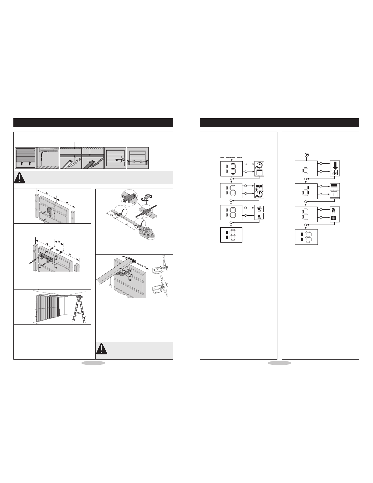
Advice for installation of the operator
• Make sure that the door is in good mechanical condition.
• Make sure, that the door is balanced.
• Make sure that the door opens and closes correctly.
• Remove all components that are not required (e.g. cords, chains, angles etc.).
• Switch off all devices which will not be needed after the operator is installed.
• Before laying cables, the operator must be disconnected from the power supply.
Wait 10 seconds to be sure that the operator is without power.
• Observe the local safety regulations.
• Always lay mains and control cables separately. The control voltage is 24 V DC.
• Only mount the operator when the door is closed.
• Install all impulse and control devices (e.g. RC code keypad) within sight to the door and at a safe distance from
movable parts of the door. A minimum mounting height of 1.5 m must be maintained.
• Permanently attach the warning decals against jamming in a clearly visible place.
• Following installation, ensure that door parts do not protrude onto public footpaths or streets.
Advice for initial operation of the operator
After initial operation, the door system operating personnel or their proxies must be familiarised with the use of the
system.
• Make sure that children cannot access the door control unit.
• Before moving the door, make sure that there are neither persons nor objects in the operating range of the door.
• Test all existing emergency command devices.
• Never insert your hands into a running door or moving parts.
Advice for maintenance of the operator
To guarantee problem-free operation, regularly check and, if necessary, repair the following aspects. Always disconnect
the operator from the power supply before carrying out any work on the door system.
• Check monthly whether the operator reverses when the door encounters an obstacle. Depending on the door’s
operational direction, place a 50 mm high/wide obstacle in the door travel path.
• Check the settings of the "OPEN" and "CLOSE" automatic cut-out function.
• Check all movable parts of the door and operator system.
• Check the door system for signs of wear or damages.
• Check whether the door can be easily moved by hand.
Advice for cleaning the operator
For cleaning never use: water jets, high pressure cleaners, acids or bases.
• Clean the operator with a dry cloth if necessary.
Page 41

Page 40
12. Attachment
12.8 Declaration of incorporation
This Declaration of Incorporation has been prepared by the powered garage door operator manufacturer to meet the
requirements of the Supply of Machinery (Safety) Regulations {Machinery Directive} and signifies that the
accompanying powered garage door operator, if installed in accordance with the manufacturer’s detailed
instructions, will be suitable to be incorporated with a suitably designed garage door with a compatible
Declaration of Incorporation.
It is the responsibility of the installing company to ensure that doors and drive units are correctly matched prior to
installation.
It is also the responsibility of the installing company, as the Responsible Person, to ensure that a suitably nominated
person should confirm that the power operated door has been installed in accordance with the instructions provided by
both the door and drive unit manufacturer.
It is also the responsibility of the installing company to check after installation the operation of the power operated
door and that any safety devices provided are suitable for the application and are all working satisfactorily.
This will permit the nominated person to attach a CE label identifying the name of the installing company, a unique
door reference number and a date of completion, and to complete and issue a Declaration of Conformity (see note
below).
One copy of the Declaration of Conformity is to be issued to the client and one copy is to be retained by the installing
company, together with the relevant two Declarations of Incorporation. In accordance with the requirements of the
Machinery Directive and the UK supply of Machinery (Safety) Regulations, these records are to be retained on file for
a period of ten years.
Note
Duplicate printed pads set out in the format of Declarations of Conformity in order to allow on site completion are
available at a reasonable cost from the DSMA for both members and non-members. Alternatively, for an additional
cost, a technical records file with full details of requirements and procedures for compliance, and including the
necessary filing divisions, is also available.
The Door & Shutter Manufacturers’Association, 42 Heath Street,
Tamworth, Staffordshire B79 7JH Telephone: 01827 52337 Fax: 01827 310827
Page 5
4. Contents
Introduction
Congratulations on the purchase of your new automatic garage door operator. It is designed to offer you convenience,
durability and quality. This operator has been factory tested to ensure maximum quality and safety.
In order to prevent damage to the garage door or garage door operator and to comply with the Machinery Directive it
is important that this operator is fitted in accordance with these instructions.
Drive rail supplied in separate carton.
P
8910
4 / 1
#73606 (inc. #47170, #73948, #73916) #74335
#47170 #73948 #73916

Page 6
5. Safety features
• Automatic Door Reverse
An unmodified closing door will automatically reverse within 2 seconds if door is obstructed by person or object.
• Automatic Time Reverse
Closing door will automatically reverse if the door is not fully closed within 80 seconds.
• Safety Stop
Opening door will immediately stop when obstructed by person or object.
• Photocell (beam break)
For additional safety we recommend a Photocell (beam break) is installed. If the INFRA-RED BEAM is broken
by a person or object whilst the door is closing, it will automatically reverse to the fully open postion without
actually having touched the closing door itself.
5 / 1
Page 39
12. Attachment
12.7 EC Declaration of Conformity
We herewith declare that the product sold by us and
mentioned below corresponds in its design, construction
and version to the relevant and basic safety and health
requirements of the following
EC regulations: EMC Directive, Machinery Directive
and Low Voltage Directive.
Product changes made without our consent will render
this Declaration void.
Product:
Relevant EC Regulations:
- EC EMC Directive (89/336/EWG),
- Machinery Directive
(98/37/EWG) and
- Low Voltage Directive
(73/23/EWG and 93/68/EWG).
Applied harmonised standards, in particular:
EN 292-1
EN 61000-6-2
EN 61000-6-3
EN 55014
EN 61000-3-2
EN 61000-3-3
EN 60335-1
EN 60335-2-95
EN 12445
EN 12453
EN 300220-1
EN 301489-3
ETS 300683
Date / Signature
12.6 Manufacturer’s Declaration
We herewith declare that the product sold by us and
mentioned below corresponds in its design, construction
and version to the relevant and basic safety and health
requirements of the following
EC regulations: EMC Directive, Machinery Directive
and Low Voltage Directive.
Product changes made without our consent will render
this Declaration void.
Product: Cardale DC650N III
Relevant EC Regulations:
- EC EMC Directive (89/336/EWG),
- Machinery Directive
(98/37/EWG) and
- Low Voltage Directive
(73/23/EWG and 93/68/EWG).
Applied harmonised standards, in particular:
EN 292-1
EN 61000-6-2
EN 61000-6-3
EN 55014
EN 61000-3-2
EN 61000-3-3
EN 60335-1
EN 60335-2-95
EN 12445
EN 12453
EN 300220-1
EN 301489-3
ETS 300683
01.10.2003 ppa. Enneking

Page 38
12. Attachment
XH5T
XH7T
XH1T
XH5C
XP3
XP4
XP5
XP6
XHG7
MA-1
MA-2
XHL5
XHG1
XHG2
XHG3
XHG8
XB1
XP1
XP2
XHG8
XHG6
XHG5
XHI1
12.5 / 2
Page 7
Attention:
Where the operator has been specified with a
2-piece boom, please refer to the assembly
instructions for this item supplied with the
boom.
1. Install grey motorshaft adapter onto motorshaft.
Bolt rail with brackets and screws to
motorhousing.
Make sure the screws are tightly fastened.
2. Fit the red slider that re-engages the emergency
release and operator pull bar onto carriage.
a. Refer to fig. 6 / 2 to fit the red slider that re-
engages the emergency release knob onto
carriage.
b. Refer to fig. 6 / 3 to fit pull bar onto carriage.
Note position of emergency release cord to
ensure correct cord position after installation.
6. Operator Assembly
P
6 / 1
6 / 2
6 / 3

Page 8
7. Carriage quick release
1. Pull cord ''A'' to disengage. Carriage re-engage remain disengaged. See fig. 7 / 1.
2. Move red slider ''b'' in direction of arrow to re-engage carriage at next movement.
Start operator. See fig. 7 / 2.
7 / 1 7 / 2
A
Page 37
12. Attachment
12.5 Replacement parts overview
XRD1
XRB1
XRB5
XRD2
XRA1
XRA5
XRC1
XRD4
XRA2
XRA3
XRA4
XRD3
XRB2
XRB3
XRB4
XB1
XB1
XRE
AF
TM-4
TM-8
AG
AB-1
XB1
XB1
AH
AC
12.5 / 1

Page 36
12. Attachment
12.4 Technical specifications
Electrical data
Connected loads 230 V
Frequency 50 Hz
Power consumption 0.7 A
Power input –operation 0.20 KW
Power input –stand-by approx. 3.9 W
Operating mode (time) 2 min.
Control voltage 24 V DC
Protection category motor head IP 20
Protection class II
Lighting 1 x 40 W E14
Mechanical data
Door travel speed 0.14 m/s with "soft" start and "soft" stop
Max. push and pull force 650N
Nominal force 150N
General data
Temperature range -20 to 60 °C
Features / Safety functions
- Reference point technology
- Soft-Start / Soft-Stop
- Delay safety device
- Automatic cut-out
- Blocking protection
- Under voltage protection
- Excess travel stop
- Electronic travel cut-out
- Connection for pushbuttons, code buttons and key switches
- Connection possibility of potential-free limit switch message for signal light circuit board
- Error messages
Accessories
- Modular antenna, 868 MHz, IP 65
- Mounting supports for sectional doors
- Release kits for swinging doors
- Adapter arm for retractable up-and-over doors
- Fittings for winged doors
- Photocells
- Emergency release kits
8.2.A 1-Piece up-and-over doors
1. Install door bracket at centre position of door and
rail bracket on centre position above door. Make
sure there is at least 10 mm. clearance between
highest travel point of door and rail.
2. Level and mount operator.
3. Disengage carriage from chain or belt!
Door may only be moved with moderate speed.
4. Connect operator pull bar to door bracket.
Attention:
Remove or disable all door locks before
installation!
Page 9
min. 35 mm
10 mm
P
8.2.A / 1
8.2.A / 2
8.2.A / 3
8.2.A / 4
8.1 Determine garage door type
Determine your garage door type as indicated in Step 8.2.A, 8.2.B, 8.2.C, 8.2.D
Follow the individual instructions required for your specific garage door type.
If your garage door type is not included, please contact your distributor.
Special accessories or operator modifications may be required.
8. Operator Installation

4. Disengage carriage from chain or belt.
Door may only be moved with moderate speed.
5. Connect operator pull bar to door bracket.
Attention:
Remove or disable all door locks before
installation!
Attention:
A photocell is strongly recommended for use with sectional doors (available separately)!
Page 10
1. Fix adjustable door bracket to top section at the
centre of the door.
2. Install rail bracket on centre position above door.
Make sure there is at least 10 mm clearance
between highest travel point of door and rail.
3. Level and mount operator.
8. Operator Installation
8.2.B Sectional doors
min. 35 mm
10 mm
8.2.B / 1
8.2.B / 2
8.2.B / 3
P
8.2.B / 4
8.2.B / 5
Page 35
12.3 Short Programming -
Advanced settings part 2
12. Attachment
h
g
j
h
g
j
h
g
j
12.2 / 2
h
g
j
h
g
j
h
g
j
567
1
2
1
2
12.3 / 1 > 10 sec.

Page 34
12.2 Short Programming -
Advanced settings part 1
12.1 Short Programming -
Basic settings
12. Attachment
h
g
j
h
g
j
j
h
g
j
h
g
j
h
g
j
h
g
j
h
g
j
h
g
j
h
g
j
h
g
j
A
B
C
D
12.1 / 1 12.2 / 1
> 2 sec. > 5 sec.
Page 11
8.3 Completion of installation
Advice:
For all other door types please contact your
distributor!
1. Make sure motorhousing and rail are mounted
correctly and secured.
Strengthen where needed.
2. Install light bulb.
Type E14, max. 40 Watt (not included).
3. Insert the modular receiver in the opening of the
operator. See fig. 8.3/1.
4. Plug the mains cable into the operator.
5. Connect the operator mains plug with the power
supply.
Attention!
Before you start Operator programming
please make sure your carriage is engaged to
chain or belt and door arm is attached to
door.
8. Operator Installation
P
12345678910
Class
2
8.3 / 1

Page 12
8. Operator Installation
8.4 Limit cam position (reference point clip)
In case you have to install a new limit cam on to your chain, please follow below instructions.
It is only possible to install a clip onto a chain. When you have a belt drive boom, it is not possible to reinstall a limit
cam.
Motorhead side
Reference point clip
should be 960 mm
(+/- 30 mm) from
motorhead side
Carriage Door side
Chain clip can be
manually connected.
Belt clip can only be
factory installed
Before connecting the
reference point clip, the
carriage must be at max.
front (door side) position.
8.4 / 1
Page 33
11. Advanced settings
Menu-Nr. E
Set "dead man function"
1. Letter E blinks.
2. Use + or - to set deadman function.
1 deadman function overrules all
2 photocell overrules deadman function (only E-King photocell as programmed in Menu 4)
3. Press P to store and to finish setting up the advanced settings part 2.
The operator is now in operational (normal) mode.

Page 32
11. Advanced settings
11.2 Advanced Setings part 2
To Set Up Advanced Settings part 2:
Menu-Nr. c
Set impulse type on terminal connector 6
(contact to 0V terminal connector 7)
Operator is in normal operating mode.
1. Press P for 15 seconds until Nr. c blinks.
2. Release P when Letter c blinks.
3. Use + or –to set the signal light function:
A Impulse NO contact
B Impulse NC contact
C Stop and reverse contact NO
D Stop and reverse contact NC
E Door open period function ON/OFF with timer (ie from 10:00 to 12:30)
F Open only for induction loop
3. Press P to store and go to Menu-Letter d.
Menu-Nr. d
Set door reverse
1. Letter d blinks.
2. Use + or - to set door reverse.
1 short door reverse
2 full door reverse
3. Press P to store and go to Menu-Letter E.
A B C D E F G H ________
Page 13
9.1 Operator Control Panel Indications
Display of door or operator modes:
Operational mode
Door is open
Door is closed
Door at intermediate position
During movement 1 sec. illuminated when
reference point passed
RC transmitter is sending a signal
Push buton impulse is activated
Door is moving in open direction
Door is moving in down direction
Photocell is interrupted
Vacation lock activated1
1De-activate vacation lock with optional 3-function wall
console or by briefly pressing "P" button on operator.
Adjustment buttons:
Program button "decrease" and close test button
Program button "increase" and open test button
Programming button
Legend:
LED off
LED illuminated
LED blinking
LED rapid blinking
9. Progamming

Page 14
9.2 Programming Overview
9. Progamming
Basic Settings
1. Programming 'door open' position
2. Programming 'door closed' position
3. Programming of hand transmitter code
Advanced Settings part 1 Explanation Factory settings
Add photocell (beam break) Setting whether the operator runs with or without photocell 1 = No
Set maximum opening force The maximum lifting force (linear line) 8
Set maximum closing force The maximum push force (linear line) 8
Set offset (sensitivity) for learned
opening force The sensitivity of learned opening force 7
Set offset (sensitivity) for learned
closing force The sensitivity of learned closing force 7
Set operator speed up The operator speed in opening direction 16 = 16/16
Set operator speed down The operator speed in closing direction 16 = 16/16
Set soft stop The soft stop before closing the door 2 = 200mm
Automatic closing Door open period set at 30sec. / 1sec. warning / external signal
light blinking. 1 = off
Set start-up warning phase before
door opens
Setting whether a signal light will flash before the door starts to
move in opening direction 1 = deactivated
Set external relay function The external optional relay can be programmed for external
blinking or illuminated signal light 1 = GDO run solid
Page 31
11. Advanced settings
Menu-Nr. 18
Set external relay function
1. Nr. 18 blinks.
2. Use + or - to set the signal light function
Possible Settings:
A Illuminated during motor movement
B Blinking during operator movement
C Illuminated as internal operator light (timed)
D Short impulse output (1 sec.)
E Illuminated while Error with operator
F Break-in alarm function warning (only when backdrive of motor detected)
G Relay on when door closed position is reached
H Relay is on when door open position is reached
3. Press P to store and to finish setting up the advanced settings part 1.
The operator is now in operational (normal) mode.
A B C D E F G H ________

Page 30
11. Advanced settings
Menu-Nr. 13
Automatic closing
Advice:
Will only function when photocell installed
1. Nr. 13 blinks.
2. Use + or –to change preset values:
A Off
B 30sec. door open / 1sec. warning phase / external light blinking
3. Press P to store and go to Menu-Nr. 16.
Menu-Nr. 16
Set start-up warning phase before door opens
1. Nr. 16 blinks.
2. Use + and - to change the start-up warning phase.
minimum phase: 0 seconds (factory set)
maximum phase: 7 seconds
Possible Settings (seconds):
3. Press P to store and go to Menu-Nr. 18.
A B ––––––––
012345678_______
Page 15
9. Progamming
Advanced Settings part 2 Explanation Factory settings
The terminal connector 6 can be
programmed for various types of
accessory connections
1 = Impulse NO contact Set door reverse
The door reverse can be program-
med 1 = Full door open reverse Set 'dead man' function
The 'dead man' feature can be
programmed. Deadman or photocell
overrules
1 = deadman overrules
Factory reset
Press P button for >30 All programmed menus will be reset to factory settings

Page 16
9.3 Preparation for Programming
•The operator has to be mounted ready for operation
•The door is not yet closed completely
•If there is a photocell (beam break), it should be
connected!
Advice:
If a photocell is to be mounted, it has to be
installed before programming of the door end
positions.
Only in this case it will be recognized
automatically by the operator.
•When the door operator is turned on (plug in power
cord) it runs a self-test; Nr. 18 will illuminate and
operator 230V light will illuminate for approximately
2 seconds. When the light is off and Nr. 1 is
illuminated the operator is in normal operating mode.
Adjustment Buttons:
All settings and adjustments can be made with the three
adjustment buttons.
to change settings of chosen program menu
to store menu setting and go to next menu.
Advice:
The programming is cancelled if none of the
three buttons (P, +, -) is actuated during a
time period of more than 120 sec. All
functions saved before with button P remain
unchanged. When programming is cancelled,
letter E is flashing.. After shortly pressing
button P the error message Nr. 7 is displayed.
Attention:
The operator has two programming levels.
For normal operation of the operator you
only program the door end positions and the
remote control in the Basic settings.
Changes in the extended programming level
may only be carried out by specialists!
Error Message
Advice:
In case of a malfunction the control Nr. E
(MALFUNCTION) is flashing.
Check 'error messages' table for further
details.
When Nr. E is flashing shortly press “P”
button to retrieve error number.
Reference Point
When the operator passes the reference point
sensor the middle segment of Nr. 8 (display 18) is
illuminated for approximately 1 second.
Advice:
The door end positions can only be
programmed if there is a valid reference
point.
Factory reset
All menus can be reset by a RESET function to the ori-
ginal values set by factory. Reset is activated by press &
hold the P button for 30 seconds until nr. 9 starts to
count down to nr. 0. Release "P" button when nr. 18 is
visible.
Advice:
The factory default setting and the reset
position for the control unit is in the
CLOSED end position. For this reason,
in order to guarantee trouble-free
programming, the door must be in the
CLOSED end position.
9. Progamming
Page 29
11. Advanced settings
Menu-Nr. 9
Set operator speed up
1. Nr. 9 blinks.
2. Use + or - to change the operator speed up.
minimum speed: 7
maximum speed: 16 (factory set)
Possible Settings:
3. Press P to store and go to Menu-Nr. 10.
Menu-Nr. 10
Set operator speed down
1. Nr. 10 blinks.
2. Use + or - to change the operator speed down.
minimum speed: 7
maximum speed: 16 (factory set)
Possible Settings:
3. Press P to store and go to Menu-Nr. 11.
Menu-Nr. 11
Set soft stop
1. Nr. 11 blinks.
2. Use + or –to change soft stop options
A no soft stop
B 200mm. soft stop
C 300mm. soft stop
D 400mm. soft stop
3. Press P to store and go to Menu-Nr. 13.
A B C D –––––––––

Page 28
Menu-Nr. 7
Set offset (sensitivity) for learned opening force
Attention:
The learning power limit is set automatically.Only change it if necessary (error No. 17).
Always test the max. allowed operating forces according to EN 12445 and EN 12453!
1. Nr. 7 blinks.
2. Use + or - to change offset.
Deactivated: 1
minimum offset: 2
maximum offset: 16
Possible Settings:
3. Press P to store and go to Menu-Nr. 8.
Menu-Nr. 8
Set offset (sensitivity) for learned closing force
Attention:
The learning power limit is set automatically.Only change it if necessary (error No. 17).
Always test the max. allowed operating forces according to EN 12445 and EN 12453!
1. Nr. 8 blinks.
2. Use + or - to change offset.
Deactivated: 1
minimum offset: 2
maximum offset: 16
Possible Settings:
3. Press P to store and go to Menu-Nr. 9.
11. Advanced settings
Page 17
9.4 Operator Programming - Basic Settings
Menu Overview:
1. Set door OPEN position
2. Set door CLOSED position
3. Program hand transmitter
To Set Up The Operator:
Attention:
Make sure the internal receiver is installed (see page 13).
Press transmitter button once before you start with operator programming –basic settings
Menu-Nr. 1:
Set door open position
Operator is in normal operating mode.
1. Press P for 3 seconds until Nr. 1 blinks.
2. Release P when Nr. 1 blinks.
3. To move the garage door to desired fully open position press AND hold the + (open) button until
desired door open position is reached. For fine-tuning use the + (open) and - (close) buttons.
Advice:
The reference point has to be passed 1x. All LED segments will switch OFF for 1sec. when limit switch is
activated WHILE in programming mode. Refer to Chapter 9.1 when motor is in operational mode.
4. Once door position is correct press P to store and go to Menu-Nr. 2.
Menu-Nr. 2:
Set door close position
1. Nr. 2 blinks.
2. To move the garage door to desired fully CLOSED position press & hold the - until desired door close
position is reached.
For fine-tuning use the - (close) and + (open) buttons.
Advice:
The reference point has to be passed 1x. All LED segments will switch OFF for 1sec. when limit switch is
activated WHILE in programming mode. Refer to Chapter 9.1 when motor is in operational mode.
3. Once door position is correct press P to store and go to Menu-Nr. 3.
9. Progamming

Page 18
9. Progamming
Menu-Nr. 3:
Program the transmitter code
1. Nr. 3 blinks.
2. Press transmitter button until Nr. 3 blinks rapidly.
3. Press P to store multi-bit transmitter code and to finish basic programming. Nr. 1 of 18 will be
illuminated indicating operator is in operational (normal) mode.
Making Adjustments:
To change the settings of an individual menu:
1. Press P for approximately 2 seconds until Menu-Nr. 1 blinks
2. Follow individual instructions for chosen menu
3. Repeatedly press P to scroll through the menus
When you reach last menu by pressing P the operator will automatically return to operational mode
(Nr. 1 of 18 is illuminated).
If an individual programming menu is skipped its settings remain unchanged.
Page 27
Menu-Nr. 6
Set maximum closing force
Attention:
The automatic cut-out is set automatically. Only change it if necessary (error No. 10).
Always test the max. allowed operating forces according to EN 12445 and EN 12453!
Advice:
The setting of the automatic cut-out corresponds to the maximum power of the operator. At the first travel
to OPEN or CLOSE direction after 'POWER ON' the automatic cut-out is effective according to the adjust-
ment. For further travels the self-learned power, that is more sensitive, is effective. The automatic cut-out is
still the upper limit of power.
1. Nr. 6 blinks.
2. By pressing + and - set the desired maximum closing force.
Possible Settings:
3. Once maximum closing force is set press P to store and go to Menu-Nr. 7.
Attention:
When re-programming the end positions (Basic settings) the closing force is learned once more.
With new setting of the end positions the force values are determined automatically. Depending on the door
travel properties increasing of the force values may be necessary.
11. Advanced settings

Page 26
11. Advanced settings
To Set Up Advanced Settings:
Menu-Nr. 4
Add photocell (Only E-King photocell which is an optional accessory)
Operator is in normal operating mode.
1. Press P for 5 seconds until Nr. 4 blinks.
2. Release P when Nr. 4 blinks.
3. A. Press + if a photocell is to be installed (Nr. 2 flashes)
B. Press - if no photocell is to be installed (Nr. 1 flashes)
4. Press P to store settings and to go to Menu-Nr. 5.
Menu-Nr. 5
Set maximum opening force
Attention:
The automatic cut-out is set automatically. Only change it if necessary (error No. 10).
Always test the max. allowed operating forces according to EN 12445 and EN 12453!
Advice:
The setting of the automatic cut-out corresponds to the maximum power of the operator. At the first travel
to OPEN or CLOSE direction after 'POWER ON' the automatic cut-out is effective according to the adjust-
ment. For further travels the self-learned power, that is more sensitive, is effective.
The automatic cut-out is still the upper limit of power.
1. Nr. 5 blinks.
2. By pressing + and - set the desired maximum lifting force.
Possible Settings:
3. Once maximum opening force is set press P to store and go to Menu-Nr. 6.
Attention:
When re-programming the end positions (basic settings) the opening force is learned once more.
With new setting of the end positions the force values are determined automatically. Depending on the door
travel properties increasing of the force values may be necessary.
Page 19
9. Progamming
9.5 Function test
Test run of the maximum required lifting force
Control:
After installing the operator the following test runs and checks must be carried out.
After setting the end positions, the operator adopts the maximum required lifting force during the first two runs.
•Run the operator (with coupled door) without interruptions:
1 x from the CLOSED end position to the OPEN end position and back.
During this test run, the operator determines the maximum opening and closing lifting force as well as the reserve
power (offset value) which is required to move the door
Advice:
These settings remain unchanged even if power supply is interrupted. The maximum required OPEN and
CLOSE lifting force reverts back to the factory default settings only when the reset button is pressed.

Page 20
9. Progamming
9.6 How to program an additional
transmitter
Advice:
- Both sides of the plug connections can be
used identically.
- For multi-channel hand transmitters this
step has to be carried out separately for
each button.
Attention:
- An actuation of the hand transmitter may
start the door movement!
- After the hand transmitter has been reco-
ded, the garage door system to be actuated
must also be reprogrammed to adopt the
new coding, since the old coding has been
irretrievably lost!
Learning the coding
This function is meant to transmit the coding of an
existing hand transmitter to an additional hand
transmitter.
Step 1
•Connect both hand transmitters by means of the
enclosed coding plug (1).
Step 2
•Actuate the existing hand transmitter and hold the
button.
The LED on the transmitter is on.
Step 3
•Actuate the desired button of the new hand
transmitter and hold the button of the existing hand
transmitter.
After 1 - 2 sec. the LED on the new transmitter is
glowing permanently.
Programming is terminated.
The new hand transmitter has now taken over the
coding of the existing hand transmitter.
•Remove the coding plug (1).
Altering the coding
It is possible to change the coding of the hand
transmitter in case that a hand transmitter has gone
lost.
For this insert the coding plug (1) into the hand
transmitter that has to be reprogrammed.
Step 1
•Insert the coding plug 1 into the hand transmitter.
•Short-circuit one of the outer pins of the coding plug
with the centre lead (e.g. by means of a screwdriver).
•Actuate the desired button on the hand transmitter.
The integrated random program generates a new
code. The LED is flashing quickly.
As soon as the LED on the hand transmitter is on
permanently, release the button of the hand transmitter
and remove the coding plug.
9.6 / 1
9.6 / 2
9.6 / 3
9.6 / 4
1
1
Page 25
Attention:
Programming the advanced features of this operator must only be undertaken by fully trained and qualified
personnel. Please contact your dealer for details.
11.1 Advanced Setings part 1
Attention:
When using "Automatic Closing" a photocell must be connected and programmed in accordance with
Menu-Nr. 4.
Advice:
If a photocell is to be mounted, it has to be installed before programming of the door end positions.
Only in this case it will be recognized automatically by the operator.
The values for the automatic cut-out (= max. force) and learning power limit (= offset in power curve) can
be set manually in the advanced settings programming level.
A setting should always be carried out as soon as a less sensitive setting has to be chosen due to door travel
properties caused by site conditions, as otherwise the automatic cut-out or power limit would react and
cause malfunctions.
In general you have to take care that the allowed operating forces according to
EN 12445 and EN 12453 are not exceeded.
The setting of the automatic cut-out corresponds to the maximum power of the operator.
At the first travel to OPEN or CLOSE direction after 'POWER ON' the automatic cut-out is effective
according to the adjustment. For further travels the self-learned power, that is more sensitive, is effective.
The automatic cut-out is still the upper limit of power.
11. Advanced settings
Table of contents
Other Cardale Garage Door Opener manuals
Popular Garage Door Opener manuals by other brands

Sears
Sears CRHFTSMBN Series owner's manual

DoorHan
DoorHan RSD01 Installation and operating instructions

Ryobi
Ryobi GD201 Addendum manual

Motorline professional
Motorline professional SLIDE1024 User's and installer's manual

Genie
Genie IntelliG 1000 Operation & maintenance manual

Control-A-Door
Control-A-Door Controll-A-Door ShedMaster installation instructions