Cardin ZVL341.03 User manual

PROGRAMMATORE ELETTRONICO MONOFASE-TRIFASE PER IL COMANDO DI PORTE E PORTONI MOTORIZZATI
SINGLE-THREEPHASE PHASE ELECTRONIC PROGRAMMER CONTROLLING MOTORISED GATES AND DOORS
PROGRAMMATEUR ELECTRONIQUE MONOPHASÉ-TRIPHASÉ POUR COMMANDE DE PORTES MOTORISEES
EINPHASEN-DREIPHASEN STEUERUNGSEINHEIT FÜR DIE AUTOMATISIERUNG VON TÜREN UND TOREN
PROGRAMADOR ELECTRONICO MONO/TRIFÁSICA PARA EL CONTROL DE LAS PUERTAS MOTORIZADAS
AVVERTENZE Pag. 3
ISTRUZIONI PER L’INSTALLAZIONE Pag. 3
MONTAGGIO CONTENITORE Pag. 4
COLLEGAMENTO ELETTRICO Pag. 5
FUNZIONI SCHEDA LOGICA Pag. 6
ISTRUZIONI PER L’UTENTE Pag. 28
REMARKS Pag. 8
INSTALLATION INSTRUCTIONS Pag. 8
CONTAINER INSTALLATION Pag. 9
ELECTRICAL CONNECTION Pag. 10
LOGIC CARD FUNCTIONS Pag. 11
INSTRUCTIONS FOR THE USER Pag. 28
REMARQUE Pag. 13
INSTRUCT. POUR L’INSTALLATION Pag. 13
MONTAGE DU BOÎTER Pag. 14
BRANCHEMENT ÉLECTRIQUE Pag. 15
FONCTIONS CARTE LOGIQUE Pag. 16
INSTRUCTIONS POUR L’UTILISATION Pag. 29
ANWEISUNGEN Seite 18
INSTALLATIONSANLEITUNGEN Seite 18
MONTAGE DES GEHÄUSES Seite 19
ELEKTROANSCHLUSS Seite 20
FUNKTIONEN DER LOGIKKARTE Seite 21
ANLEITUNGEN FÜR DEN BENUTZER Seite 29
ADVERTENCIAS Pag. 23
INSTRUCCIONES PARA L’INSTALACIÓN Pag. 23
MONTAJE DEL CONTENEDOR Pag. 24
CONEXIONES ELECTRICAS Pag. 25
FUNCIONES TARJETA LÓGICA Pag. 26
INSTRUCCIONES DE USO Pag. 30
ITALIANO
ENGLISH
ESPAÑOL
DEUTSCH
FRANÇAIS
PRG384
MOD: 11-06-2013
PRG384
ZVL341.03
This product has been tried and tested in
the manufacturer's laboratory, during the
installation of the product follow the sup-
plied indications carefully.
CARDIN ELETTRONICA spa
Via del lavoro, 73 – Z.I. Cimavilla
31013 Codognè (TV) Italy
Tel: +39/0438.404011
Fax: +39/0438.401831
Http: www.cardin.it

2
5
AP.
3412
Comune
CH.
M
TD
14131211
10
9
876
FTC_S
24V.ac
LS
LP
FTC_I
24V.ac
24V.ac
TAL
2423222120191817
TB
TC
TA
FCC
FCA
+
PW
Jumper
TB
DC0343 CS1068B.01
BSP
AP
25 26
1615
27
OUT EF
+-
4
4
4
7
5
6
8
1
2
3
10 10
10 10
Opening
10 10
Closing
Scheda base
PRG384
13-09-2001
DC0343 Description :
Product Code :
Date :
Drawing number :
P.J.Heath
CARDIN ELETTRONICA S.p.A - 31020 San Vendemiano (TV) Italy - via Raffaello, 36 Tel: 0438/401818 Fax: 0438/401831
Draft :
All rights reserved. Unauthorised copying or use of the information contained in this document is punishable by law
YPR384B01CE
NO NO NC NO
NO
Dimensioni d'ingombro
External dimensions
Dimensions d’encombrement
Außenabmessungen
Dimensiones maximas
Scheda base
Mother board
Carte de base
Basisplatine
Tarjeta básica
Interruttore generale monofase-trifase
Singlephase/threephase mains switch
Interrupteur général monophasé-triphasé
Einphasen-Dreiphasen-Hauptschalter
Interruptor general monofásico-trifásico
265
175
105
Panello comandi
PRG383
02-04-2000
DM0157 Description :
Product Code :
Date :
Drawing number :
P.J.Heath
CARDIN ELETTRONICA S.p.A - 31020 San Vendemiano (TV) Italy - via Raffaello, 36 Tel: 0438/401818 Fax: 0438/401831
Draft :
All rights reserved. Unauthorised copying or use of the information contained in this document is punishable by law
PRG383
PRG383
18-01-95
DM0126 Description:
Product Code :
Date :
Drawing number :
P.J.Heath
CARDIN ELETTRONICA S.p.A - 31020 San Vendemiano (TV) Italy - via Raffaello, 36 Tel: 0438/401818 Fax: 0438/401831
Draft :
All rights reserved. Unauthorised copying or use of the information contained in this document is punishable by law
BLOCCO PORTA TRIFASE
68
N°4
N°6
N°2
Collegamento blocco porta
380-400V3~
T
R
S
400V3~
Legenda
1 Ricevitore a scheda
2 Scheda logica
3 Bloccoporta
4 N°3 fusibili 10 Amp. 500V (6,3x32 rapidi)
5 Fusibile 1A - protezione sovraccarichi
circuito 24V (rapido)
6 Fusibile 375mA (ritardato)
protezione trasformatore
7 Morsettiera di potenza
8 Morsettiera di comando
TB Ponticello selezione secondo canale
AP Connettore pulsantiera
PW Led scheda alimentata
Legend
1 Receiver card
2 Logic board
3 Door security switch
4 N°3 fuses 10 Amp. 500V (6,3x32 rapid action)
5 Fuse 1A - 24V overload protection
(rapid action)
6 Fuse 375mA (delayed)
transformer protection
7 Mains terminal board
8 Command terminal board
TB Second channel selection jumper
AP Control button interface
PW Power on led
Légende
1 Récepteurs à carte
2 Carte logique
3 Dispositif de verrouillage porte
4 Nbre 3 fusible 10 Amp. 500V (6,3x32)
(rapide)
5 Fusible 1A - protection surcharges 24V
(rapide)
6 Fusible 375mA (retardé)
protection transformateur
7 Bornier de puissance
8 Bornier de commande
TB Pont sélection deuxième canal
AP Connecteur pour boutons-poussoirs
extérieurs
PW Led carte alimentée
21
3
Zeichenerklärung
1 Empfängerkarte
2 Logikkarte
3 Türsicherheitsblockierung
4 3 Schmelzsicherungen 10 Amp. 500V (6,3x32
(ink)
5 Schmelzsicherungen 1A - Überlastungsschutz 24V
(ink)
6 Schmelzsicherungen 375mA (ink)
Transformatorschutz
7 Anschlussklemmleiste für Leistungsaufnahme
8 Anschlussklemmleiste für Steuerung
TB Überbrückung zur Wahl des zweiten Kanals
AP Verbinder Drucktastentadel
PW Led - Stromversorgung der Karte
Leyenda
1 Receptor con caja
2 Tarjeta lógica
3 Dispositivo de bloqueo de seguridad
4 N°3 fusibles 10 Amp. 500V (6,3x32 rápido)
5 Fusible 1A - protección sobrecargas 24V
(rápido)
6 Fusible 375mA (retrasado)
protección transformador
7 Bornera potencia
8 Bornera mando
TB Puente selección segundo canal
AP Conector para pulsadores exteriores
PW Pilota tarjeta sometida a tensión

3
ITALIANO AVVERTENZE
Prima di dar inizio all’installazione leggere attentamente il presente fascicolo.
In particolare, prendere visione dei dispositivi di sicurezza previsti dal prodotto per utilizzarli
con la massima efcacia.
Non tutti i dispositivi di sicurezza eventualmente resi obbligatori da norme vigenti in Italia o
all’estero sono presi in considerazione dal presente fascicolo. L’installatore dovrà provvedervi
personalmente, integrando i dispositivi mancanti ed installandoli a monte o a valle dei prodotti
descritti nel presente fascicolo.
L’utilizzo dei prodotti e la loro destinazione ad usi diversi da quelli previsti e/o consigliati, non
è stata sperimentata dal costruttore, pertanto i lavori eseguiti sono sotto la completa respon-
sabilità dell’installatore.
Il presente manuale si rivolge a persone abilitate all'installazione di
“APPARECCHI UTILIZZATORI
DI ENERGIA ELETTRICA ”
e richiede una buona conoscenza della tecnica , esercitata in forma
professionale. Il costruttore declina ogni responsibilità per eventuali danni provocati dalla
mancata osservanze nell'installazione delle norme di sicurezza attualmente in vigore.
Descrizione
- elettronica composta da scheda madre, con scheda logica estraibile inserita sugli appositi
connettori ad innesto obbligato
- contenitore da esterno in ABS con portello ad anta ssato su cerniere in acciaio cromato
(apertura 180°), guarnizione di tenuta in chiusura (IP 55)
- chiusura del portello, a chiave con blocco porta di sicurezza
- ssaggi a parete previsti sul contenitore
- ingresso cavi di collegamento con pressacavo
- collegamenti a bassissima tensione di sicurezza
- predisposizione innesto ricevitore radiocomando
- pulsanti esterni sullo sportello (opzionali)
ISTRUZIONI PER L'INSTALLAZIONE
Caratteristiche tecniche
Alimentazione trifase Vac 400V3~
Frequenza Hz 50-60
Motori N° 1
Potenza Max. motore trifase W 2200
Corrente di cortocircuito con fusibili Amp.t<300 ms 20
Corrente nominale Amp 5
Temperatura di esercizio °C -20…+55
Grado di protezione IP 55
Grado di protezione con tasti IP 54
Grado di Ignifugazione UL94 V0
Centrale provvista di pressatubi per inserimento tubo Ø16 mm
Il kit PRG384 comprende:
- Il programmatore PRG384
- Una serie di viterie per il montaggio a muro
- Due chiavi
- Il libretto d'istruzioni
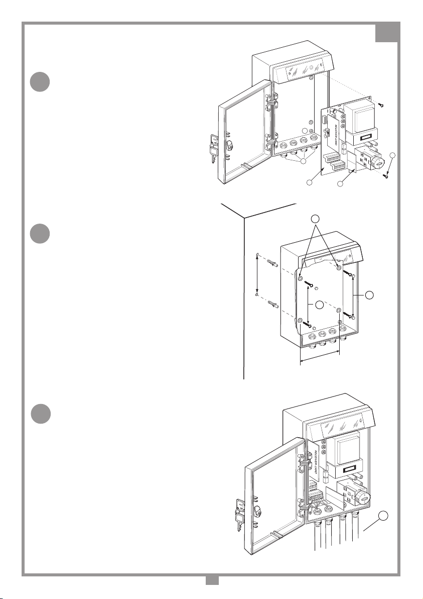
Posizionamento
In base alla tipologia e alle caratteristiche d'impianto individuare il punto di posa dell'apparec-
chiatura. L'apparecchiatura dovrà essere collocata:
- al riparo da urti e manomissioni
- ad altezza sufciente dal suolo, al riparo da possibili colmi d'acqua
- in una posizione facilmente raggiungibile dal tecnico, per interventi di manutenzione.
ITALIANO

4
Procedura di montaggio del
contenitore:
•Svitare le viti “B” ed estrarre il circuito “C” dal
contenitore con cura riponendolo momenta-
neamente a riparo da polvere e possibili urti.
•Tracciare (con l'ausilio della scatola ) i quattro
punti di ssaggio a muro;
•Fissare il contenitore utilizzando quattro viti
e tasselli “G” ed inserire i tappi di copertura
viti “H”.
•Controllare il corretto ssaggio dei pressatubi
“D” (g. 4A) alla scatola.
• Reinserire il circuito nel contenitore e ssarlo
con le apposite viti “B” (g. 4A).
•Inserire i tubi di collegamento “I” sugli appo-
siti pressatubi. I cavi della linea 400V3 ven-
gono fatti passare nei tubi 1 e 2 (vedi gura),
separati dai cavi di collegamento in bassa
tensione che passano nei tubi 3 e 4.
•Effettuare i collegamenti elettrici seguendo lo
schema allegato (vedi g. 5).
PRG
27-04-98
DM0138 Description :
Product Code :
Date :
Drawing number :
P.J.Heath
CARDIN ELETTRONICA S.p.A - 31020 San Vendemiano (TV) Italy - via Raffaello, 36 Tel: 0438/401818 Fax: 0438/401831
Draft :
All rights reserved. Unauthorised copying or use of the information contained in this document is punishable by law
Inserimento scheda PRG383
D
A
E
C
B
LPRG
27-04-98
DM0135 Description :
Product Code :
Date :
Drawing number :
P.J.Heath
CARDIN ELETTRONICA S.p.A - 31020 San Vendemiano (TV) Italy - via Raffaello, 36 Tel: 0438/401818 Fax: 0438/401831
Draft :
All rights reserved. Unauthorised copying or use of the information contained in this document is punishable by law
Installazione contenitore PRG
F
G
H
160 MM
130 MM
PRG
27-04-98
DM0139 Description :
Product Code :
Date :
Drawing number :
P.J.Heath
CARDIN ELETTRONICA S.p.A - 31020 San Vendemiano (TV) Italy - via Raffaello, 36 Tel: 0438/401818 Fax: 0438/401831
Draft :
All rights reserved. Unauthorised copying or use of the information contained in this document is punishable by law
Inserimento pressatubi PRG383
4321
I
4A
4
4B
4C

5
Collegamento elettrico
Accertarsi, prima di eseguire il collegamento elettrico, che la tensione e la frequenza riportate sulla
targhetta caratteristiche corrispondano a quelle dell'impianto di alimentazione.
INTERRUTTORE GENERALE TRIFASE: (g. 3 pag. 2)
Collegare i cavi di alimentazione direttamente sul blocco porta
2/4/6 Alimentazione trifase 400V3~
COLLEGAMENTI MORSETTIERA
1 Ingresso terra alimentazione generale
2 Uscita terra motore
3-4-5 Comando motore trifase (apertura-chiusura-comune)
6-7 Uscita positivo/negativo 24Vdc per elettrofreno
8-9 Uscita 24Vac 10W lampeggiatore segnalazione di moto
9-10 Uscita 24Vac 3W lampada spia porta aperta
11-12 Uscita 24Vac 5W alimentazione dispositivi esterni
13 FTCI (contatto N.C.) ingresso fotocellula di inversione moto in fase di chiusura
(a uomo presente causa l'arresto del moto)
14 FTCS (contatto N.C.) ingresso fotocellula di stop, blocca il movimento in apertura e chiusura
per il tempo che rimane impegnata; se la richiusura automatica è abilitata, dopo il tempo di
pausa esegue la manovra di chiusura.
15 Comune
16 TD (contatto N.A.) ingresso tasto dinamico (Apre-Chiude)
17 Centrale antenna RX radio
18 Massa antenna RX radio
19 FCA (contatto N.C.) ingresso necorsa di apertura
20 FCC (contatto N.C.) ingresso necorsa di chiusura
21 Comune
22 TA (contatto N.A.) ingresso tasto di apertura
23 TC (contatto N.A.) ingresso tasto di chiusura
24 TB (contatto N.C.) ingresso tasto di blocco
25 TAL (contatto N.A.) ingresso tasto di apertura limitata (se la richiusura automatica è inserita,
allo scadere del tempo di pausa parte la manovra di chiusura).
26-27 BSP (contatto N.C.) ingresso sicurezza passiva
Se aperto interrompe l'alimentazione alla parte di comando, compresa l'elettronica. Inserire
un contatto normalmente chiuso in grado di sopportare un carico di 30Vdc 100mA. Questo
dispositivo di sicurezza viene installato in aggiunta ai normali dispositivi di sicurezza attiva
(Attenzione! Non è possibile collegare questo ingresso in serie ad FTCI, FTCS, TB dato che la
BSP non ha lo stesso comune). Il suo collegamento può essere fatto sulla costa pneumatica
ssa come anticonvogliamento o su dispositivi di estrema emergenza, sempre rispettando le
norme in vigore.
N.B. TUTTI I CONTATTI N.C. NON UTILIZZATI VANNO PONTICELLATI
5
AP.
3412
Comune
CH.
M
TD
14131211
10
9
876
FTC_S
24V.ac
LS
LP
FTC_I
24V.ac
24V.ac
TAL
2423222120191817
TB
TC
TA
FCC
FCA
+
PW
Jumper
TB
DC0343 CS1068B.01
BSP
AP
25 26
1615
27
OUT EF
+-
4
4
4
7
5
6
8
1
2
3
10 10
10 10
Opening
10 10
Closing
Scheda base
PRG384
13-09-2001
DC0343 Description :
Product Code :
Date :
Drawing number :
P.J.Heath
CARDIN ELETTRONICA S.p.A - 31020 San Vendemiano (TV) Italy - via Raffaello, 36 Tel: 0438/401818 Fax: 0438/401831
Draft :
All rights reserved. Unauthorised copying or use of the information contained in this document is punishable by law
YPR384B01CE
NO NO NC NO
NO
5

6
FUNZIONI SCHEDA LOGICA
Legenda
PR: Tasto di programmazione
LPR: Led di programmazione
D1: Dip-switch selezione funzioni
LED SPIA: TB-FTCS-FTCI
Stato di funzionamento delle sicurezze
Led accesi:
sicurezze a riposo (o ponticellate
se non utilizzate)
Led spenti:
sicurezze in avaria, in
fase di intervento o non ponticellate
se non utilizzate
FUNZIONI SCHEDA LOGICA ESTRAIBILE
1) Tempo di lavoro: 0-120 secondi
L’anta viene considerata completamente aperta (e dunque la richiusura automatica viene eseguita) anche quando
il tempo di apertura è terminato e non è stato attivato il necorsa FCA; programmare il tempo di apertura in modo
da avere sempre un margine in più rispetto all’arrivo dell’anta al necorsa FCA.
2) Tempo di pausa: 0-120 secondi
Regolare il tempo di pausa in relazione alle caratteristiche del motore: se tale tempo è molto breve, appena l’anta
arriva a completa apertura esegue un’inversione molto rapida.
SELEZIONI A DIP-SWITCHES (D1)
DIP 1: On => richiusura automatica abilitata.
Off => richiusura automatica disabilitata.
DIP 2: On => modalità “uomo presente” attivata.
Off => modalità “uomo presente” disattivata.
DIP 3: On => modalità TD: “apertura-chiusura” con inversione solo in fase di chiusura.
Off=>modalità TD: “apertura-blocco-chiusura-blocco”
NOTA: per impostare i dip-switches: disalimentare il programmatore, cambiare le impostazioni, quindi dare nuo-
vamente alimentazione.
PROGRAMMAZIONE TEMPI DI LAVORO (APERTURA LIMITATA, APERTURA E PAUSA)
1. Con porta completamente chiusa, premere e tenere premuto per 4 secondi il tasto “PR”: il LED “LPR” deve
essere inizialmente spento, per poi iniziare a lampeggiare velocemente segnalando l’ingresso in modalità di
programmazione. La lampada spia viene attivata ad intermittenza con la stessa frequenza dell’accensione del
LED. Rilasciare il tasto “PR”.
NOTA: se premendo il tasto “PR” il LED “LPR” si accende subito e resta costantemente acceso, signica che
il programmatore non si trova nello stato di completa chiusura, per cui non si riuscirà ad entrare in modalità di
programmazione; togliere e ridare alimentazione al programmatore.
Se premendo il tasto “PR” il LED “LPR” lampeggia signica che è stato riscontrato un errore nei dati in memoria: il
programmatore è bloccato, e bisogna programmare nuovamente i tempi (vedere paragrafo “segnalazioni d’allarme”).
Se le sicurezze (TB, FTCI, FTCS) non sono a riposo, oppure se il necorsa di apertura risulta attivato, la program-
mazione tempi non è abilitata.
6
32 1
ON
LPR FTCI FTCS TB
PR
TCS
PR
CS1112B.01
D1
Logica PRG401 (cs1112AB.01)
YPR302
05-03-2001
DC0325 Description:
Product Code :
Date :
Drawing number :
P.J.Heath
CARDIN ELETTRONICA S.p.A - 31020 San Vendemiano (TV) Italy - via Raffaello, 36 Tel: 0438/401818 Fax: 0438/401831
Draft :
All rights reserved. Unauthorised copying or use of the information contained in this document is punishable by law

7
Durante la programmazione tempi, l’attivazione di TB, FTCI e FTCS causa il blocco dell’anta e del conteggio del
tempo, che riprende non appena le sicurezze tornano allo stato di riposo.
2) Premere nuovamente il tasto “PR” (oppure azionare il “TD” o il radiocomando) e tenerlo premuto nché l’anta
avrà raggiunto la posizione di apertura limitata. Al rilascio del tasto il motore si blocca, per poi riprendere la
manovra di apertura (ed il conteggio del tempo di lavoro) dopo un secondo di attesa.
3) Quando viene attivato il necorsa di apertura, si ha il blocco del motore ma il conteggio del tempo di lavoro
prosegue, per poter dare un margine di tempo in più rispetto all’esatto tempo di manovra.
4) Premere il tasto “PR” (oppure azionare il “TD” o il radiocomando): il conteggio del tempo di lavoro termina. La
lampada spia viene ora attivata con intermittenza più lenta: è iniziato il conteggio del tempo di pausa.
5) Trascorso il tempo di pausa desiderato, premere un’altra volta il tasto “PR” (oppure azionare il “TD” o il
radiocomando): inizia la chiusura e allo stesso tempo si esce dalla procedura di programmazione.
***** LEGGERE ATTENTAMENTE LE SEGUENTI NOTE *****
• Quando viene data tensione di alimentazione, se il necorsa di apertura risulta attivato ed è selezionata la
richiusura automatica, dopo il tempo di pausa si vericherà la chiusura.
• Quando viene data tensione di alimentazione, anche con anta non completamente chiusa, la logica non permette
comandi di chiusura, ma soltanto di apertura. L’unica eccezione si ha quando il necorsa di apertura è attivato.
• Con anta completamente aperta, l’attivazione di FTCI e di TA causa un reset del conteggio del tempo di pausa.
• Il comando di apertura limitata è utilizzabile solamente con anta completamente chiusa; non è possibile dunque
dare due comandi di apertura limitata in successione. Se in fase di chiusura dopo un’apertura limitata si ha
l’attivazione di FTCI, la riapertura risulta ancora limitata (non riapre completamente).
MODALITÀ DI FUNZIONAMENTO DELLA LAMPADA SPIA
L’uscita per lampada spia (24Vac, 3W) viene utilizzata per segnalare lo stato dell’anta:
• A cancello completamente chiuso: lampada spia spenta
• A cancello non completamente chiuso: lampada spia accesa
SEGNALAZIONI D’ALLARME
1) Parametri errati in memoria EEPROM
Se si verica un errore nella lettura dei dati da EEPROM si ha una segnalazione mediante lampada spia, che
viene attivata ad intermittenza: il sistema risulta bloccato. Bisogna dunque entrare in programmazione tempi per
correggere l’errore. Premendo il tasto “PR” si vedrà lampeggiare subito il LED “LPR”.
2) Attivazione contemporanea dei finecorsa
L’attivazione contemporanea dei necorsa (guasto) causa il blocco del programmatore nché persiste il problema,
con l’attivazione del lampeggiante per tre secondi, con periodo di ripetizione di 6 secondi.
Quando viene ripristinato il corretto stato dei necorsa, si ha un RESET automatico e la ripresa del normale fun-
zionamento.

8
REMARKS
Before commencing with the installation of this appliance make sure that you have read the following
instructions carefully. In particular familiarise yourself with the safety devices required by the system,
only then will you be able to use them to great effect.
Not all of the safety devices required by the safety standards have been taken into consideration in this
manual. The installer must make sure that any eventual safety devices required by the local standards
and regulations have been installed both ahead of and after the products described in this manual.
This appliance must be used exclusively for the purpose for which it has been made. Any non
authorised modications are to be considered improper and therefore dangerous. The manufacturer
accepts no liability for damage caused by, or situations arising from, the improper use of these
appliances and therefore all work carried out after the delivery of the appliance is to be considered
the complete responsibility of the installer.
These instructions are aimed at professionally qualied “installers of electrical equipment” in
conformity with the local standards in force.
Description
- the electronic components consist of a mother board with an extractable logic card inserted into one of
the interface slots.
- all weather container in ABS with a stainless steel hinged inspection door (180° opening angle), door
sealing gasket (IP 55)
- lockable inspection door with security mains switch
- container tted with wall fastening elements
- power cable inlet complete with cable clamp
- low power terminal board connections
- radio control receiver interface
- external control buttons (available on request)
INSTALLATION INSTRUCTIONS
Technical specifications
Threephase power supply Vac 400V3~
Frequency Hz 50-60
Motors Nr. 1
Maximum power consumption motors (threephase) W 2200
Short circuit current with fuses Amp.t<300 ms 20
Nominal current input Amp 5
Operating temperature °C -20…+55
Protection grade IP 55
Protection grade with external control buttons IP 54
Fire protection grade UL94 V0
Container tted with cable clamps for Ø16 mm pipes
The PRG384 kit contains:
- The programmer PRG384
- A series of wall mounting screws etc.
- Nr. 2 keys
- The instruction manual
Positioning
Depending on the type of installation work out the position in which the programmer will be situated
remembering that the site must be:
- a position safe from accidental collision
- high enough above the ground to be safe from pools of water
- in a position which the technician can easily reach.
ENGLISH ENGLISH

9
Container installation procedure
• Removethe screws “B” andcarefullyextract the
P.C.B. card “C” from the container remember-
ing to store it somewhere safe from dust and
possible damage.
• Using the container as a template mark the four
points at which the fastening holes are to be
drilled;
• Fasten the container using four screws and raw
plugs “G” and insert the screw covering plugs
“H”.
• Insert the pipe ttings “D” (g.4A) and check
that they are fastened correctly.
• Re-insert the electronic card into the container
and fasten down using the screws “B” (g.4A)
• Insert the rigid electrical connection pipes “I”
into the cable tubes. The 400V3 power cables
should be passed through pipes 1 and 2 (see
gure) so as to separate them from the low
voltage wires which should be passed through
pipes 3 and 4.
• Carry out the electrical connection following the
attached wiring diagram (see g. 5).
PRG
27-04-98
DM0138 Description :
Product Code :
Date :
Drawing number :
P.J.Heath
CARDIN ELETTRONICA S.p.A - 31020 San Vendemiano (TV) Italy - via Raffaello, 36 Tel: 0438/401818 Fax: 0438/401831
Draft :
All rights reserved. Unauthorised copying or use of the information contained in this document is punishable by law
Inserimento scheda PRG383
D
A
E
C
B
LPRG
27-04-98
DM0135 Description :
Product Code :
Date :
Drawing number :
P.J.Heath
CARDIN ELETTRONICA S.p.A - 31020 San Vendemiano (TV) Italy - via Raffaello, 36 Tel: 0438/401818 Fax: 0438/401831
Draft :
All rights reserved. Unauthorised copying or use of the information contained in this document is punishable by law
Installazione contenitore PRG
F
G
H
160 MM
130 MM
PRG
27-04-98
DM0139 Description :
Product Code :
Date :
Drawing number :
P.J.Heath
CARDIN ELETTRONICA S.p.A - 31020 San Vendemiano (TV) Italy - via Raffaello, 36 Tel: 0438/401818 Fax: 0438/401831
Draft :
All rights reserved. Unauthorised copying or use of the information contained in this document is punishable by law
Inserimento pressatubi PRG383
4321
I
4A
4
4B
4C

10
Electrical connection
Before connecting the appliance make sure that the voltage and frequency rated on the data plate
conform to those of he mains supply.
THREEPHASE MAIN SWITCH:(g. 3 pag. 2)
Connect the power cables directly to the door security switch
2/4/6 Threephase power supply 400V3~
TERMINAL BOARD CONNECTIONS
1 Earth binding post (mains supply)
2 Motor earthing wire (output)
3-4-5 Three phase motor output Opening- Closing- Common
6-7 Electronic braking device positive/negative 24Vdc output
8-9 24Vac 10W ashing warning lamps indicating gate in movement
9-10 24Vac 3W output. Indicates that the gate/door is open.
11-12 24Vac 5W output, powering external devices (Photoelectric cells, etc.)
13 FTCI (contact N.C.) Safety and control devices input (photo-cells invert the travel direction when
an obstruction is detected) .
14 FTCS (contact N.C.) Safety and control devices in input
(photoelectric cells stopping the gate when an obstruction is detected) The opening of this contact
will block all movement, during opening and closing, until the obstruction has been removed, due
to the safety device cutting in, the gate will then continue moving until it reaches a travel limit.
15 Common for all inputs and outputs (negative)
16 TD (contact N.O.) Dynamic button input “Open-Close”
17 Radio receiver antenna pole
18 Mass for radio receiver antenna
19 FCA opening travel limit input (contact N.C.)
20 FCC closing travel limit input (contact N.C.)
21 Common for all inputs and outputs (negative)
22 TA (contact N.O.) Opening button input
23 TC (contact N.O.) Closing button input
24 TB (contact N.C.) Blocking button input.
25 TAL Limited opening button. If the automatic re-closing function is inserted the closing movement
will be activated after the pause time has expired.
26-27 BSP Passive safety input (N.C.)
If this contact is open the power supply to the controls (including the electronic card) will be inter-
rupted. Insert a normally closed contact which is able to support a load of 30Vdc 100mA. This
safety device should be installed in addition to the normal active safety devices (Caution! This input
cannot be connected in series with the FTCI,FTCS, TB as they do not share the same common).
It could also be wired in series to a xed position anti-crush buffer or be used an emergency device
in line with the local standards and regulations in force.
N.B.: ALL UNUSED NC CONTACTS MUST BE JUMPED
5
AP.
3412
Comune
CH.
M
TD
14131211
10
9
876
FTC_S
24V.ac
LS
LP
FTC_I
24V.ac
24V.ac
TAL
2423222120191817
TB
TC
TA
FCC
FCA
+
PW
Jumper
TB
DC0343 CS1068B.01
BSP
AP
25 26
1615
27
OUT EF
+-
4
4
4
7
5
6
8
1
2
3
10 10
10 10
Opening
10 10
Closing
Scheda base
PRG384
13-09-2001
DC0343 Description :
Product Code :
Date :
Drawing number :
P.J.Heath
CARDIN ELETTRONICA S.p.A - 31020 San Vendemiano (TV) Italy - via Raffaello, 36 Tel: 0438/401818 Fax: 0438/401831
Draft :
All rights reserved. Unauthorised copying or use of the information contained in this document is punishable by law
YPR384B01CE
NO NO NC NO
NO
5

11
LOGIC CARD FUNCTIONS
Legend
PR: Programming button
LPR: Programming LED
D1: Function selection dip-switch
Indicator leds: TB-FTCS-FTCI
Safety device status
Lit leds indicate safety devices at rest or
jumped if not used
Leds off indicate that the safety devices
are functioning incorrectly (damaged), in
the process of intervening (working) or
incorrectly jumped (unused safety devices)
EXTRACTABLE LOGIC CARD FUNCTIONS
1) Work time: 0-120 seconds
The door is considered completely open (and therefore automatic reclosing is carried out) even
when the opening time has ended and the FCA travel limit has not intervened; program the opening
times so as to leave a margin greater than the time required to reach the opening travel limit FCA.
2) Pause time: 0-120 seconds
Set the pause time according to the characteristics of the motor; if that time is very brief the gate
will carry out a rapid travel direction inversion as soon as it reached the completely open position.
DIP-SWITCH SETTINGS (D1)
DIP 1: On => automatic re-closing enabled.
Off => automatic re-closing disabled.
DIP 2: On => “manual mode” activated.
Off => “manual mode” disactivated.
DIP 3: On => TD mode: “open-block-close-block”
Off => TD mode: “open-close” with inversion only during the opening stage.
Note: to set the dip-switches; turn off the power to the programmer, change the settings and then
switch the power back on.
WORK TIME PROGRAMMING (LIMITED OPENING, OPENING AND PAUSE)
1) With the door completely closed, press and hold down the “PR” button for 4 seconds. The led
“LPR” will be off to start with and will then start to ash rapidly indicating that the programming
mode has been entered. The indicator light will ash intermittently at the same frequency as
the indicator led. Release the “PR” button.
Note: if you press the “PR” button and the led “LPR” lights up straight away (and remains lit) it
means the programmer is not in the completely closed state and you cannot enter the program-
ming mode. Switch the power off and on again.
If you press the “PR” button and the led “LPR” ashes it means that a memory data error has
been encountered; the programmer will be blocked and you will have to reprogram the work times.
(see paragraph “alarm conditions”).
If the security devices (TB, FTCI, FTCS) are not at rest or the opening travel limit is activated, time
programming will not be enabled.
6
32 1
ON
LPR FTCI FTCS TB
PR
TCS
PR
CS1112B.01
D1
Logica PRG401 (cs1112AB.01)
YPR302
05-03-2001
DC0325 Description:
Product Code :
Date :
Drawing number :
P.J.Heath
CARDIN ELETTRONICA S.p.A - 31020 San Vendemiano (TV) Italy - via Raffaello, 36 Tel: 0438/401818 Fax: 0438/401831
Draft :
All rights reserved. Unauthorised copying or use of the information contained in this document is punishable by law

12
During time programming the activation of TB, FTCI or FTCS will force the gate and the time count
to stop; as soon as the security devices are reset the time count and gate movement will continue.
2) Press the “PR” button (or activate either “TD” or the radio control) and keep it pressed until
the gate reaches the limited opening position. When the button is released the motor will stop.
It will continue the opening movement (and the work time count) after a period of 1 second.
3) When the opening travel limit is activated the motor will block but the work time count will carry
on in order to give a slightly higher time margin with respect to the exact manoeuvring time
4) Press the “PR” button (or activate either “TD” or the radio control): the work time count will end.
The warning light is still receiving power but the indicator lamp will now be ashing at slower
intervals: the pause time count has now started.
5) When the pause time is sufcient, press the “PR” button again (or activate either “TD” or the
radio control) the closing cycle will start and you will exit the programming procedure.
***** READ THE FOLLOWING NOTES CAREFULLY *****
• When the unit is powered up; if the opening travel limit is active and automatic re-closing has
been selected the gate/door will close after the pause period has expired.
• When the unit is powered up with the gate/door not completely closed the logic will only allow
the opening command and not the closing command. The only exception occurs when the
opening travel limit is active.
• With the gate/door fully open, activating “FTCI” or “TA” will force a pause time reset.
• The limited opening command can only be used with the gate completely closed; it is not pos-
sible to give two successive limited opening commands. If the FTCI is activated after a limited
opening command has been received during the closing cycle the gate opening will still be
limited (it will not open completely).
INDICATOR LIGHT FUNCTION MODES
The (24Vac, 3W) indicator lamp output is used to indicate the gate/door status:
• When the gate/door is completely closed: Indicator lamp off
• Gate/door moving in the opening direction: Indicator lamp on
ALARM INDICATIONS
1) Wrong parameters in EEPROM memory
If there is a data read error from EEPROM the warning lamp will indicate the error by ashing inter-
mittently: the system will be blocked. You will have to enter work time programming to correct the
error. Pressing the “PR” button will force the LED “LPR” to ash straight away.
2) Simultaneous travel limit activation
Simultaneous travel limit activation will cause the programmer to block as long as the problem
exists. The warning light will stay on for 3 seconds and will be activated every 6 seconds.
When the travel limits have been freed an automatic reset will occur and normal operation will return.

13
REMARQUE
Avant de procéder à l’installation, lire attentivement ce livret. En particulier, se familiariser avec
les dispositifs de sécurité prévus sur le produit an de pouvoir les utiliser au mieux.
Les dispositifs de sécurité, rendus éventuellement obligatoires par les normes en vigueur en
Italie et à l’étranger, ne sont pas tous pris en considération dans ce livret.
L’installateur devra y remédier personnellement en installant les dispositifs manquants en
amont ou en aval des produits décrits dans ce livret.
Une diverse utilisation des produits ou leur destination à un usage différent de celui prévu et/
ou conseillé n’a pas été expérimentée par le Fabricant. Par conséquent, les travaux effectués
sont sous la responsabilité exclusive de l’installateur.
Ce livret est destiné à des personnes titulaires d’un certicat d’aptitude professionnelle pour
l’installation d'APPAREILS ÉLECTRIQUES (aux termes de la loi N.46 du 5.3.1990) et requiert
une bonne connaissance de la technique appliquée professionnellement.
Le Fabricant ne peut en aucun cas être tenu responsable d'éventuels dommages causés
par l'inobservation des normes de sécurité actuellement en vigueur.
Descriptif
- Électronique composée d'une carte de base, avec carte logique extractible et enchable.
- Coffret en ABS pour l'extérieur avec portillon sur charnières en acier chromé (ouverture
180°), joint d’étanchéité en fermeture (IP 54).
- Fermeture à clé du portillon avec dispositif de verrouillage.
- Éléments pour xation murale prévus sur le coffret.
- Entrée des câbles de branchement avec presse-étoupe.
- Raccordements à très basse tension, de sécurité.
- Prédisposition pour insertion récepteur télécommande radio.
- Boutons extérieurs sur le portillon (en option).
INSTRUCTIONS POUR L'INSTALLATION
Caractéristiques techniques
Alimentation triphasée Vac 400V3~
Fréquence Hz 50-60
Moteurs Nbre 1
Puissance maxi. moteur triphasé W 2200
Courant de court-circuit avec fusibles Amp. t<300 ms 20
Courant nominal Amp 5
Température de fonctionnement °C -20…+55
Indice de protection IP 55
Indice de protection avec boutons IP 54
Indice d'ignifugation UL94 V0
Coffret équipé de presse-étoupes pour l’introduction
de tuyaux Ø16
Le kit PRG384 comprend:
- un programmateur PRG384
- la visserie pour le montage au mur
- 2 clés
- un livret d’instructions
Implantation
En fonction du type et de la particularité de l’installation, déterminer l’endroit d’implantation de
l’appareil. Ce dernier devra être positionné de façon telle qu’il soit:
- à l’abri de chocs et d'actes de vandalisme;
- à une certaine hauteur du sol pour être protégé en cas d’inondation.
- facilement accessible par le technicien qui devra s'occuper de la maintenance.
FRANÇAIS FRANÇAIS

14
Montage du coffret
• Dévisser les vis “B”, extraire doucement
le circuit “C” du coffret et le déposer
momentanément à un endroit à l’abri de
poussière et de chocs.
• Tracer (à l’aide du coffret) les quatre points
de xation au mur.
• Fixer le coffret au moyen de quatre vis et
chevilles “G” et appliquer les caches “H” sur
les vis.
• S'assurer de la xation correcte des
presse-étoupes “D” (g. 4A) au coffret.
• Réinsérer le circuit dans le coffret et le xer
par les vis “B” prévues à cet effet (g. 4A).
• Engager les tuyaux de branchement “I” dans
les presse-étoupes. Les câbles de la ligne
400V3 devront être passés dans les tuyaux
1 et 2 (voir gure) pour qu'ils soient séparés
des câbles de branchement de basse tension
passant dans les tuyaux 3 et 4.
• Effectuer les branchements électriques sui-
vant le schéma annexé (voir g. 5).
PRG
27-04-98
DM0138 Description :
Product Code :
Date :
Drawing number :
P.J.Heath
CARDIN ELETTRONICA S.p.A - 31020 San Vendemiano (TV) Italy - via Raffaello, 36 Tel: 0438/401818 Fax: 0438/401831
Draft :
All rights reserved. Unauthorised copying or use of the information contained in this document is punishable by law
Inserimento scheda PRG383
D
A
E
C
B
LPRG
27-04-98
DM0135 Description :
Product Code :
Date :
Drawing number :
P.J.Heath
CARDIN ELETTRONICA S.p.A - 31020 San Vendemiano (TV) Italy - via Raffaello, 36 Tel: 0438/401818 Fax: 0438/401831
Draft :
All rights reserved. Unauthorised copying or use of the information contained in this document is punishable by law
Installazione contenitore PRG
F
G
H
160 MM
130 MM
PRG
27-04-98
DM0139 Description :
Product Code :
Date :
Drawing number :
P.J.Heath
CARDIN ELETTRONICA S.p.A - 31020 San Vendemiano (TV) Italy - via Raffaello, 36 Tel: 0438/401818 Fax: 0438/401831
Draft :
All rights reserved. Unauthorised copying or use of the information contained in this document is punishable by law
Inserimento pressatubi PRG383
4321
I
4A
4
4B
4C

15
Branchement électrique
Avant d’effectuer le branchement électrique, contrôler que la tension et la fréquence indiquées sur la
plaquette signalétique correspondent à celles du réseau d’alimentation.
INTERRUPTEUR GÉNÉRAL TRIPHASÉ (g. 3 page 2)
Brancher les câbles d'alimentation directement sur le dispositif de verrouillage du portillon
(gure 3).
2/4/6 Alimentation triphasée 400V3~.
BRANCHEMENTS DU BORNIER
1- Entrée terre alimentation générale.
2- Sortie terre moteur.
3-4-5 Commande moteur triphasé (ouverture-fermeture-commun).
6-7 Sortie positif/négatif 24Vdc pour électrofrein.
8-9 Sortie 24Vac 10W clignoteur pour signalisation de mouvement.
9-10 Sortie 24Vac 3W lampe témoin porte ouverte.
11-12 Sortie 24Vac 5W alimentation dispositifs externes.
13 FTCI (contact N.F.) entrée cellule photoélectrique d'inversion du mouvement en phase de
fermeture (durant un fonctionnement manuel, elle interrompt la manoeuvre).
14 FTCS (contact N.F.) entrée cellule photoélectrique de blocage. Elle interrompt les manoeuvres
d'ouverture et de fermeture tant qu'elle est occultée; si la refermeture automatique est validée,
la manoeuvre de fermeture se déclenchera après que le temps d'arrêt se soit écoulé.
15 Commun.
16 TD (contact N.O.) entrée touche dynamique (Ouverture-Fermeture).
17 Âme antenne récepteur radio.
18 Masse antenne récepteur radio.
19 FCA (contact N.F.) entrée n de course en ouverture.
20 FCC (contact N.F.) entrée n de course en fermeture.
21 Commun.
22 TA (contact N.O.) entrée touche d'ouverture.
23 TC (contact N.O.) entrée touche de fermeture.
24 TB (contact N.F.) entrée touche de blocage N.F.
25 TAL (contact N.O.) entrée touche d'ouverture partielle (Si la refermeture automatique est validée,
la manoeuvre de fermeture se déclenche dès que le temps d'arrêt s'est écoulé).
26-27 BSP (contact N.F.) entrée sécurité passive
S'il est ouvert, il interrompt l’alimentation à la partie commande, électronique incluse. Insérer
un contact normalement fermé apte à supporter une charge de 30Vdc 100mA. Ce dispositif
de sécurité doit être ajouté aux dispositifs de sécurité active (Attention! Il n’est pas possible
de brancher en série cette entrée aux FTCI, FTCS, TB, considéré que le commun de BSP est
différent). Son branchement peut se faire sur un bord de protection anti-coincement ou sur des
dispositifs d’extrême urgence, selon les normes de sécurité en vigueur.
N.B. FAIRE DES PONTS SUR TOUS LES CONTACTS N.F. INUTILISÉS
5
AP.
3412
Comune
CH.
M
TD
14131211
10
9
876
FTC_S
24V.ac
LS
LP
FTC_I
24V.ac
24V.ac
TAL
2423222120191817
TB
TC
TA
FCC
FCA
+
PW
Jumper
TB
DC0343 CS1068B.01
BSP
AP
25 26
1615
27
OUT EF
+-
4
4
4
7
5
6
8
1
2
3
10 10
10 10
Opening
10 10
Closing
Scheda base
PRG384
13-09-2001
DC0343 Description :
Product Code :
Date :
Drawing number :
P.J.Heath
CARDIN ELETTRONICA S.p.A - 31020 San Vendemiano (TV) Italy - via Raffaello, 36 Tel: 0438/401818 Fax: 0438/401831
Draft :
All rights reserved. Unauthorised copying or use of the information contained in this document is punishable by law
YPR384B01CE
NO NO NC NO
NO
5

16
FONCTIONS DE LA CARTE LOGIQUE
Nomenclature
PR: Touche de programmation
LPR: Led de programmation
D1: Dip-switch sélection fonctions
Leds témoins: TB-FTCS-FTCI
État de fonctionnement des dispositifs
de sécurité.
Leds allumées:
dispositifs de sécurité en état de veille
(ou court-circuités s'ils ne sont pas
utilisés).
Leds éteintes:
dispositifs de sécurité en panne, en
phase d'intervention ou court-circuités
s'ils ne sont pas utilisés.
FONCTIONS DE LA CARTE LOGIQUE EXTRACTIBLE
1) Temps de travail 0-120 secondes
La porte est considérée comme étant complètement ouverte (donc, la refermeture s'effectuera automatiquement)
même si le temps d'ouverture s'est écoulé et le n de course FCA n'a pas été activé; programmer un temps d’ouver-
ture de façon à toujours avoir une marge de temps en plus par rapport à l’arrivée de la porte au n de course FCA.
2) Temps d'arrêt 0-120 secondes
Régler le temps d’arrêt en fonction des caractéristiques du moteur; si ce temps est très court, dès que la porte
atteint la position d’ouverture complète, la refermeture se déclenche immédiatement.
SÉLECTION À TRAVERS DIP-SWITCHES (D1)
DIP 1: On => refermeture automatique validée.
Off => refermeture automatique invalidée.
DIP 2: On => mode de fonctionnement manuel activé.
Off => mode de fonctionnement manuel désactivé.
DIP 3: On => modalité TD: “ouverture-fermeture” avec inversion seulement en phase de fermeture.
Off=> modalité TD: “ouverture-blocage-fermeture-blocage”.
NOTA: pour la conguration des dip-switches: mettre le programmateur hors tension, régler les dip-switches et
remettre ensuite le programmateur sous tension.
PROGRAMMATION DES TEMPS DE TRAVAIL (OUVERTURE PARTIELLE, OUVERTURE ET ARRÊT)
1) Avec porte complètement fermée, garder appuyée la touche “PR” pendant 4 secondes: la LED “LPR” doit rester
éteinte quelques instants avant de commencer à clignoter rapidement pour signaler l'accès à la programmation.
La lampe témoin clignote de la même façon que la LED. Relâcher la touche “PR”.
NOTA: si à une pression sur la touche “PR”, la LED “LPR” s’allume tout de suite et reste allumée en continu, le
programmateur ne se trouve pas en condition de fermeture complète, d’où l’impossibilité d’accéder à la program-
mation; couper et remettre le courant au programmateur.
Si à une pression sur la touche “PR”, la LED “LPR” se met à clignoter, il y a une erreur au niveau des données
mémorisées: le programmateur se bloque et il faudra programmer de nouveau les temps (voir paragraphe “Signa-
lisations d’alarme”
Si les dispositifs de sécurité (TB, FTCI et FTCS) ne sont pas en état de veille ou si le n de course en ouverture
s’avère activé, la programmation des temps n’est pas faisable.
6
32 1
ON
LPR FTCI FTCS TB
PR
TCS
PR
CS1112B.01
D1
Logica PRG401 (cs1112AB.01)
YPR302
05-03-2001
DC0325 Description:
Product Code :
Date :
Drawing number :
P.J.Heath
CARDIN ELETTRONICA S.p.A - 31020 San Vendemiano (TV) Italy - via Raffaello, 36 Tel: 0438/401818 Fax: 0438/401831
Draft :
All rights reserved. Unauthorised copying or use of the information contained in this document is punishable by law

17
Durant la programmation des temps, l’activation de TB, FTCI et FTCS bloque la porte et le comptage du temps
qui reprennent dès que les dispositifs de sécurité reviennent à l’état de veille.
2) Appuyer de nouveau sur la touche “PR” (ou agir sur “TD” ou sur la télécommande) et la garder appuyée tant
que la porte n’aura pas atteint la position d’ouverture partielle. Le relâchement de la touche arrête le moteur; la
manoeuvre d’ouverture (et le comptage du temps de travail) reprendra après une seconde d’attente.
3) L’activation du n de course en ouverture bloque le moteur mais le comptage du temps de travail continue à
se dérouler pour pouvoir avoir une marge de temps en plus par rapport à la durée effective de la manoeuvre.
4) Appuyer sur la touche “PR” (ou agir sur “TD” ou sur la télécommande): à ce point, le comptage du temps de
travail prend n et la lampe témoin commence à clignoter plus lentement pour signaler que le comptage du
temps d’arrêt s'est déclenché.
5) Une fois que le temps d'arrêt souhaité s'est écoulé, appuyer une autre fois sur la touche “PR” (ou agir sur “TD”
ou sur la télécommande): à ce point, la fermeture se déclenche et on quitte la programmation.
***** LIRE ATTENTIVEMENT LA NOTICE SUIVANTE *****
• Quand le système est mis sous tension et le n de course en ouverture s’avère activé et la refermeture automa-
tique sélectionnée, la fermeture se déclenche dès que le temps d’arrêt s'est écoulé.
• Quand le système est mis sous tension sans que la porte soit complètement fermée, la logique ne permet pas
de commander la fermeture mais seulement l’ouverture, à la seule exception du cas où le n de course en
ouverture est activé.
• Avec porte complètement ouverte, l’activation de FTCI et de TA provoque une mise à zéro du comptage du
temps d’arrêt.
• La commande d’ouverture partielle ne peut être délivrée que si la porte est complètement fermée. Donc, il
n’est pas possible de commander l’ouverture partielle deux fois de suite. Si en phase de fermeture après une
ouverture partielle, la FTCI s’active, la réouverture s’effectuera encore partiellement (la porte ne s’ouvrira pas
complètement).
MODE DE FONCTIONNEMENT DE LA LAMPE TÉMOIN
La sortie pour la lampe témoin (24Vac, 3W) n’est utilisée que pour signaler l’état de la porte:
• avec porte complètement fermée: lampé témoin éteinte
• avec porte pas complètement fermée: lampe témoin allumée
SIGNALISATIONS D’ALARME
1) Paramètres erronés mémorisés en EEPROM
Une erreur de lecture des données de EEPROM est signalée par la lampe témoin qui se met à clignoter; dans ce
cas, le système se bloque. Il faudra alors accéder à la programmation des temps pour corriger l’erreur. Une pression
sur la touche “PR” fera clignoter immédiatement la LED “LPR”.
2) Activation simultanée des fins de course
L’activation simultanée des ns de course (panne) bloque le programmateur tant que le problème n’a pas été
solutionné; le clignoteur s’active alors par des clignotements de 3 secondes suivies de 6 secondes d’intervalle.
Dès que ce problème est solutionné, il se produit automatiquement une mise à zéro et le tout reprendra normalement.

18
ANWEISUNGEN
Bevor mit der Installation begonnen wird, sollte das vorliegende Heft aufmerksam gelesen werden,
insbesondere sollten die vom Produkt vorgesehenen Sicherheitseinrichtungen zwecks bester Ef-
zienz in Augenschein genommen wird.
Im vorliegenden Heft werden nicht alle von der rechtskräftigen italienischen oder ausländischen
Normen eventuell vorgeschriebenen Sicherheitseinrichtungen in Betracht gezogen. Der Installa-
teur muß persönlich dafür sorgen, daß die fehlenden Einrichtungen hinzugefügt werden und sie
den im vorliegenden Heft beschriebenen Produkten vorgeschaltet oder nachgeschaltet installie-
ren.
Die Verwendung der Produkte und ihre Zweckbestimmung zu einem anderen Gebrauch, als es
vorgesehen und/oder geraten wurde, ist nicht vom Hersteller erprobt worden. Die Installations-
arbeiten erfolgen daher unter der vollständigen Verantwortung des Installateurs. Den vorliegende
Handbuch wendet sich an Personen, die zur Installation von “ELEKTROGERÄTEN“ befähigt sind
und setz eine gute beruiche Kenntnis der Technik voraus. Der Hersteller lehnt jede Verantwortung
für eventuelle Schäden ab, die durch die fehlende Beachtung der zur Zeit geltenden Sicherheits-
normen bei der Installation entstanden sind.
Beschreibung
- Die Elektronik ist zusammengesetz aus einer Träger-Leiterplatine mit herausnehmbar Logikkarte,
die über einen Zwangskupplungsanschluß eingeführt wird.
- Außengehäuse aus ABS mit einügeliger Tür, die in Gelenken aus Chromstahl befestigt ist (Öffnung
180°). Schutzdichtung in geschlossenem Zustand (IP55).
- Schließung der Tür mittels Schlüssel mit Sicherheitsblockierung.
- Gehäuse mit Möglichkeiten zur Wandbefestigung
- Eingang der Kabel über Kabelklemmen
- Anschlüsse an sichere Niedrigstspannung
- Vorbereitet zur Einsetzung der Funkempfängerkarte
- Drucktasten außen auf der Tür (extra)
Installationsanleitungen
Technische Daten
Dreiphasen-Stromversorgung Vac 400V3~
Frequenz Hz 50-60
Motoren Nr. 1
Max. Leistung Dreiphasenmotor W 2200
Kurzschluß-Strom mit Schmelzsicherung Amp.Zeit<300 ms 20
Nennstrom Amp 5
Betriebstemperatur °C -20…+55
Schutzgrad IP 55
Schutzgrad mit Tasten IP 54
Feuerschutzgrad UL94 V0
Die Zentrale ist mit Rohrklemmen zur Einführung von Rohren
(Ø16 mm) ausgestatet.
Der Satz PRG384 beinhaltet:
- Den Programmierer PRG384
- Eine Reihe Schrauben zur Montage an der Wand
- 2 Schlüssel
- Die Betriebsanleitung
Positionierung
Die Anbringstelle der Apparatur an Hand der Typologie und der Eigenschaften der Anlage wählen. Die
Anbringstelle der Apparatur sollte folgenden Anforderungen gerecht werden:
- Geschützt vor Stößen und Beschädigungen
- Genügender Abstand vom Boden, um vor Hochwasser geschützt zu sein
- An einer für den Techniker zwecks Wartung leicht zugänglichen Stelle.
DEUTSCH DEUTSCH

19
Montageverfahren des Gehäuses
• Die Schrauben
“B” losschrauben und den
Schaltkreis “C” vorsichtig aus dem Gehäuse
entnehmen und ihn vorläug an einen vor
Staub und möglichen Stößen geschützten Ort
legen.
• Die vier Befestigungspunkte an der Mauer
(mit Hilfe des Gehäuses) anzeichnen.
• Das Gehäuse unter Verwendung von vier
Schrauben und Dübel
“G” befestigen und die
Schraubenabdeckstopfen
“H”
einsetzen.
• Die einwandfreie Befestigung der Rohrklem-
men
“D” (Abb 4A) am Gehäuse kontrollieren.
• Den Schaltkreis wieder in das Gehäuse ein-
setzen und ihn mit den dafür vorgesehenen
Schrauben
“B”
festschrauben (Abb 4).
• Die Anschlußrohre
“I” in die dafür vorgese-
henen Rohrklemmen einführen. Die Kabel der
400V3 Leitung werden durch die Rohre 1 und
2 geführt (siehe Abbildungen), also getrennt
von den Verbindungskabeln mit Niedrigspan-
nung, die durch die Rohre 3 und 4 laufen.
• Die Elektroanschlüsse unter Beachtung des
beiliegenden Schaltplans ausführen
(siehe Abb. 5).
PRG
27-04-98
DM0138 Description :
Product Code :
Date :
Drawing number :
P.J.Heath
CARDIN ELETTRONICA S.p.A - 31020 San Vendemiano (TV) Italy - via Raffaello, 36 Tel: 0438/401818 Fax: 0438/401831
Draft :
All rights reserved. Unauthorised copying or use of the information contained in this document is punishable by law
Inserimento scheda PRG383
D
A
E
C
B
LPRG
27-04-98
DM0135 Description :
Product Code :
Date :
Drawing number :
P.J.Heath
CARDIN ELETTRONICA S.p.A - 31020 San Vendemiano (TV) Italy - via Raffaello, 36 Tel: 0438/401818 Fax: 0438/401831
Draft :
All rights reserved. Unauthorised copying or use of the information contained in this document is punishable by law
Installazione contenitore PRG
F
G
H
160 MM
130 MM
PRG
27-04-98
DM0139 Description :
Product Code :
Date :
Drawing number :
P.J.Heath
CARDIN ELETTRONICA S.p.A - 31020 San Vendemiano (TV) Italy - via Raffaello, 36 Tel: 0438/401818 Fax: 0438/401831
Draft :
All rights reserved. Unauthorised copying or use of the information contained in this document is punishable by law
Inserimento pressatubi PRG383
4321
I
4A
4
4B
4C

20
Elektroanschluß
Vor der Ausführung des Elektroanschlusses sicherstellen, daß die auf dem Typenschild angegebene
Spannung und Frequenz mit denen der elektrischen Stromversorgung übereinstimmen.
DREIPHASEN-HAUPTSCHALTER (Abb. 3 Seite 2)
Die Stromversorgungskabel direkt an die Sicherheitsblockierung anschließen.
2/4/6 Dreiphasen-Stromversorgung 400V3~
KLEMMLEISTENANSCHLÜSSE
1 Eingang Erdung allgemeine Stromversorgung
2 Ausgang Motorenerdung
3-4-5 Steuerung Dreiphasenmotor (öffnen-schließen-gemeinsam)
6-7 Ausgang positiv-negativ 24Vdc für Elektrobremse
8-9 Ausgang 24Vac 10W Blinklicht zur Bewegungsanzeige
9-10 Ausgang 24Vac 3W Kontroll-Leuchte für offenes Tor.
11-12 Ausgang 24Vac 5W Stromversorgung externer Vorrichtungen
13 FTCI Eingang (Ausschaltgliedkontakt) Lichtschranke für Bewegungsumkehrung während des
Schließvorganges (verursacht bei manueller Betrieb den Bewegungsstillstand).
14 FTCS Eingang (Ausschaltgliedkontakt) Stop-Lichtschranke, blockiert die Bewegung bei der
Öffnung und Schließung für deren Beanspruchungszeit, wenn die automatische Wiederver-
schließung eingeschaltet ist, wird nach Ablauf der Pausenzeit der Schließungsvorhang ausge-
führt.
15 Gemeinsam
16 TD Dynamische Taste (Öffnung-Schließung)
17 Innenleiter Funkempfänger
18 Außenleiter Funkempfänger
19 FCA Eingang (Ausschaltgliedkontakt) Endschalter für Öffnung
20 FCC Eingang (Ausschaltgliedkontakt) Endschalter für Schließung
21 Gemeinsam
22 TA Öffnungstaste (Einschaltgliedkontakt)
23 TC Schließtaste (Einschaltgliedkontakt)
24 TB Stopptaste (Ausschaltgliedkontakt)
25 TAL Taste für begrenzte Öffnung (Wenn die automatische Wiederschließung eingestellt ist,
beginnt Ablauf der Pausenzeit der Schließungsvorhang.
26-27 Eingang Ausschaltglied passive Sicherheit
Wenn geöffnet, unterbricht er die Versorgung des Steuerteils einschließlich der Elektronik.
Einen Ausschaltglied Kontakt einsetzen, der in die Lage ist, eine Belastung von 30Vdc 100mA
zu ertragen. Diese Sicherheitsvorrichtung wird zusätzlich zu den normalen aktiven Sicherheits-
vorrichtungen installiert (Achtung! Es ist nicht möglich, diesen Eingang in Serie zu FTCI, FTCS,
TB anzuschließen, da der BSP nicht den gleichen gemeinsam Kontakt aufweist. Sein Anschluß
kann auf der festen Pneumatikschwelle als Quetschsicherung oder auf Notvorrichtungen erfol-
gen, immer unter Beachtung der geltenden Sicherheitsvorschriften.
HINWEISS: ALLE NICHT VERWENDETEN AUSSCHALTGLIED-KONTAKTE MÜSSEN ÜBERBRÜCKT WERDEN
5
AP.
3412
Comune
CH.
M
TD
14131211
10
9
876
FTC_S
24V.ac
LS
LP
FTC_I
24V.ac
24V.ac
TAL
2423222120191817
TB
TC
TA
FCC
FCA
+
PW
Jumper
TB
DC0343 CS1068B.01
BSP
AP
25 26
1615
27
OUT EF
+-
4
4
4
7
5
6
8
1
2
3
10 10
10 10
Opening
10 10
Closing
Scheda base
PRG384
13-09-2001
DC0343 Description :
Product Code :
Date :
Drawing number :
P.J.Heath
CARDIN ELETTRONICA S.p.A - 31020 San Vendemiano (TV) Italy - via Raffaello, 36 Tel: 0438/401818 Fax: 0438/401831
Draft :
All rights reserved. Unauthorised copying or use of the information contained in this document is punishable by law
YPR384B01CE
NO NO NC NO
NO
5
This manual suits for next models
1
Table of contents
Languages:
Other Cardin Controllers manuals