Cardin ELSNAP Series User manual

ITALIANO
ENGLISH
DEUTSCH
ESPAÑOL
Installation drawings /wiring diagram Pages 2-7
Important remarks Page 14
Installation instructions Pages 14-15
Electrical connection Pages 15-16
Function congurations Pages 17-18
Maintenance Page 19
Technical specications Page 48
Montagezeichnungen/elektrischer Schaltplan
Seiten 2-7
Wichtige Hinweise Seite 26
Installationsanleitung Seiten 26-27
Elektrischer Anschluss Seiten 27-28
Funktionseinstellungen Seiten 29-30
Wartung Seite 31
Technische Eigenschaften Seite 48
Planos de instalación/esquema eléctrico Páginas 2-7
Advertencias importantes Página 32
Instrucciones para la instalación Páginas 32-33
Conexionado eléctrico Páginas 33-34
Conguraciones de funciones Páginas 35-36
Mantenimento Página 37
Características técnica Página 48
ZVL656.00 - Mod: 02-10-2019
Disegni d'installazione / schema elettrico Pagine 2-7
Avvertenze importanti Pagina 8
Istruzioni per l'installazione Pagine 8-9
Collegamento elettrico Pagine 9-10
Congurazioni funzioni Pagine 11-12
Manutenzione Pagina 13
Caratteristiche tecniche Pagina 48
®
Questo prodotto è stato testato e collaudato nei laboratori della casa costruttrice, la quale ne ha verificato la perfetta
corrispondenza dellecaratteristiche conquelle richiestedalla normativavigente. Thisproduct hasbeen triedandtested in
themanufacturer's laboratorywho haveverified thatthe productconforms inevery aspectto thesafety standardsin force.
Ce produit a été testé et essayé dans les laboratoires du fabricant. Pour l'installer suivre attentivement les instructions
fournies. Dieses Produkt wurde in den Werkstätten der Herstellerfirma auf die perfekte Übereinstimmung seiner
Eigenschaftenmitdenvon dengeltendenNormenvorgeschriebenen getestetundgeprüft. Esteproductohasido probado
y ensayado en los laboratorios del fabricante, que ha comprobado la perfecta correspondencia de sus características
con las contempladas por la normativa vigente. Dit product werd uitgeprobeerd en getest in het laboratorium van de
fabrikant,
die heeft vastgesteld dat het product in alle opzichten voldoet aan de geldende veiligheidsnormen.
EL
24Vdc
Motors
Model Date
Instruction manual Series
ELSNAP RAPID/S/L 23-05-2019
ZVL656.00
CARDIN ELETTRONICA spa
Via del lavoro, 73 – Z.I. Cimavilla
31013 Codognè (TV) Italy
Tel: +39/0438.404011
Fax: +39/0438.401831
Http: www.cardin.it
BARRIERA ELETTROMECCANICA CON MOTORE 24 Vdc
ELECTROMECHANICAL BARRIER WITH A 24 Vdc POWERED MOTOR
BARRIÈRE LEVANTE ÉLECTROMÉCANIQUE AVEC MOTEUR 24 Vdc
ELEKTROMECHANISCHE SCHRANKE MIT 24 Vdc MOTOR
BARRERA ELECTROMECÁNICA CON MOTOR EN CORRIENTE CONTINUA
ELEKTROMECHANISCHE SLAGBOOM MET 24 Vdc MOTOR
FRANÇAIS
Schémas d’installation/schéma électrique Pages 2-7
Consignes importantes Page 20
Instructions pour l’installation Pages 20-21
Branchement électrique Pages 21-22
Conguration functions Pages 23-24
Maintenance Page 25
Caractéristiques techniques Page 48
ELSNAP-RAPID -ELSNAPS/L
NEDERLANDS
Installatietekeningen/bedradingsschema Blz. 2-7
Belangrijke opmerkingen Blz. 38
Installatievoorschriften Blz. 38-39
Elektrische aansluiting Blz. 39-40
Conguratie van de functies Blz. 41-42
Onderhoud Blz. 43
Technische specicaties Blz. 48

2
IMPIANTO TIPO - INSTALLATION EXAMPLE - EXEMPLE D'INSTALLATION - ANLAGENART
INSTALACIÓN ESTÁNDAR - INSTALLATIEVOORBEELD
1
LEGENDA
1 Barriera
2 Selettore a chiave
3 Fotocellule
4 Interruttore onnipolare
con apertura contatti min. 3 mm
5 Sensore magnetico
6 Asta standard
7 Lampeggiante
8 Programmatore elettronico
9 Appoggio sso
10 Prolo in gomma
11 Pannelli fotovoltaici
12 Sun Power
LEGEND
1 Barrier
2 Selector switch
3 Photocells
4 All pole circuit breaker with a min. of 3 mm
between the contacts
5 Magnetic sensor
6 Standard boom
7 Warning light
8 Electronic programmer
9 Fixed support fork
10 Passive safety edge
11 Solar panels
12 Sun Power
DIMENSIONI D’INGOMBRO - EXTERNAL DIMENSIONS
DIMENSIONS D’ENCOMBREMENT - AUSSENABMESSUNGEN
DIMENSIONES MAXIMAS - TOTALE AFMETINGEN
2
NOMENCLATURE
1 Barrière
2 Sélecteur à clé
3 Cellule photoélectrique
4 Interrupteur omnipolaire,
ouverture des contacts min. 3 mm
5 Senseur magnétique
6 Lisse standard
7 Clignoteur
8 Programmateur électronique
9 Lyre de repos
10 Prol en caoutchouc
11 Panneaux solaires
12 Sun Power
ZEICHENERKLÄRUNG
1 Schranke
2 Schlüsselschalter
3 Lichtschranken
4 Allpoliger Schalter
mit einem Kontaktenabstand von 3 mm
5 Induktionsschliefe
6 Standard-Schlagbaum
7 Blinklicht
8 Steuereinheit
9 Auagestütze
10 Gummiprol
11 Solarzellen
12 Sun Power
LEYENDA
1 Barra
2 Selector con llave
3 Fotocélulas
4 Interruptor omnipolar con apertura
entre los contactos de 3 mm como mín.
5 Sensor magnético
6 Barra estándar
7 Relampagueador
8 Central de control
9 Apoyo jo
10 Perl de caucho
11 Paneles fotovoltaicos
12 Sun Power
LEGENDA
1 Slagboom
2 Sleutelschakelaar
3 Fotocellen
4
Meerpolige schakelaar met
contactafstand van minstens 3 mm
5 Magnetische sensor
6 Standaard slagboomarm
7 Knipperlicht
8 Elektronische besturingseenheid
9 Vaste vangpaal
10 Rubber proel
11 Zonnepanelen
12 Sun Power
METAL DEC
TX RX
230V
50Hz
5
23
4
9
6
10
1
7
11
8
12
EL SNAP-RAPID - EL SNAPS - EL SNAPL
305 max. 6m230
175
1180
1010
905
L 4,25m
L 6,25m
L 3,25m
L 5,25m
SNAPPER3
SNAPPER4
SNAPPER5
SNAPPER6

3
240
160
H
G
3
FISSAGGIO BASE BARRIERA AL PLINTO DI FONDAZIONE - FASTENING THE BASE OF THE BARRIER TO THE PLINTH
FIXATION DE LA BASE DE LA BARRIÈRE À L’ASSISE - BEFESTIGUNG DER SCHRANKENBASIS AN DER FUNDAMENTPLATTE
FIJACIÓN BASE BARRERA EN EL PLINTO DE CIMENTACIÓN - BEVESTIGING VAN DE SLAGBOOMBASIS OP DE SOKKEL
3a
50
310
50
50
410
50 50
227
327
D
C
500
A
B
E
30
30
30
F
30
FIX SNAP
Contropiastra di fissaggio (opzionale)
Ground fastening base (optional)
Contre-plaque de fixation (en option)
Befestigungs Grundplatte
(extra)
Contraplaca de fijación (opcional)
Bevestigingssokkel (optioneel)
Installazione a pavimento senza contropiastra
Pavement installation without the fastening base
Installation au sol sans contre-plaque
Bodeninstallation ohne Basisplatte
Instalación en el piso sin contraplaca
Installatie op bestrating zonder
bevestigingssokkel
INSTALLAZIONE ASTA A SINISTRA/DESTRA - BOOM INSTALLATION - FIXATION DE LA LISSE
BEFESTIGUNG DES SCHLAGBAUMS - FIJACIÓN DEL ASTA - INSTALLATIE SLAGBOOMARM LINKER-/ -/RECHTERKANT
4 5
G
D
F
C
E
B
A
I
H
A
B
HF
G
I
C
D
E

4
B
C
A
INVERSIONE SENSO DI ROTAZIONE ASTA - INVERTING THE BOOM ROTATION DIRECTION - INVERSION DE L’OUVERTURE DE LA LISSE
SEITENUMKEHR SCHRANKENÖFFNUNG - INVERSIÓN DE LA APERTURA ASTA - OMKERENDRAAIRICHTING SLAGBOOMARM
6a 6b
6c
Installazione asta a sinistra
Left-hand boom installation
Fixation de la lisse à gauche
Befestigung des Schlagbaums
auf der linken Seite
Fijación de la barra a la izquierda
Installatie slagboomarm aan linkerkant
6d 6e
Installazione asta a destra
Right-hand boom installation
Fixation de la lisse à droite
Befestigung des Schlagbaums auf der rechten Seite
Fijación de la barra a la derecha
Installatie slagboomarm aan rechterkant
B
A
C
B
C
F
G
A
D
B
E
C
6

5
SCHEMA DI MONTAGGIO APPOGGIO FISSO- ASSEMBLY DRAWINGS FIXED SUPPORT - SCHÉMA DE MONTAGE DE LA LYRE DE REPOS
MONTAGESCHEMA DER AUFLAGESTÜTZEN - ESQUEMA DE MONTAJE DEL APOYO FIJO - MONTAGESCHEMA VAN DE VASTE VANGPAAL
7 7a
MANOVRA MANUALE - MANUAL MANOEUVRE- MANŒUVRE MANUELLE - MANUELLE BETÄTIGUNG
MANIOBRA MANUAL - HANDMATIGE BEWEGING
8 8a
3 m - 4 m - 6 m
150
90
S
305
50 mm
145
80 x 80
S
910
5
BA
2C
5

6
ACCESSO AL MOBILETTO - ACCESS TO THE CABINET - ACCÉDER À L' ARMOIRE
ZUGANG ZU DEM SCHRANK - ACCESO AL GABINETE - TOEGANG TOT DE KAST
9
REGOLAZIONE MECCANICA DELLA POSIZIONE ORIZZONTALE / VERTICALE ASTA
ADJUSTING THE HORIZONTAL / VERTICAL POSITION OF THE BOOM
RÉGLAGE MÉCANIQUE DE LA POSITION HORIZONTALE/VERTICALE DE LA LISSE
MECHANISCHE EINSTELLUNG DER WAAGERECHTEN / SENKRECHTEN SCHLAGBAUMSTELLUNG
REGULACIÓN MECÁNICA DE LA POSICIÓN HORIZONTAL/VERTICAL DEL ASTA
AANPASSEN VAN DE HORIZONTALE/VERTICALE STAND VAN DE SLAGBOOMARM
10a
10b
10
1
2
3
1
3
2
4
5
6
OK
1
3
2
4
5
6
OK
45° ± 5°
1
2
3

7
SCHEMA ELETTRICO IMPIANTO TIPO - STANDARD WIRING DIAGRAM - SCHÉMA ÉLECTRIQUE TYPE D'INSTALLATION - ELEKTRISCHER
SCHALTPLAN (ANLAGENART) - ESQUEMA ELECTRICO INSTALACIÓN ESTÁNDAR - STANDAARD BEDRADINGSSCHEMA
11
1
CC
2
24V 12V 0
C
165432
NA
NC NC
C
NA
FTC-RX
1
TB
2
Standard wiring diagram
PRG SNAP
05-07-2019
Description :
Product Code :
Date :
Drawing number :
P.J.Heath
CARDIN ELETTRONICA S.p.A - 31020 San Vendemiano (TV) Italy - via Raffaello, 36 Tel: 0438/401818 Fax: 0438/401831
Draft :
All rights reserved. Unauthorised copying or use of the information contained in this document is punishable by law
DC0596
PRG SNAP
CS19705 DC0595
ANT
1234
56
MOT
24V IN
FC1
FC2
10
11
(R)
(N)
25 26 27
19 20 21 22 23 24
16 17 18
15
12 13 14
L8
L7
L6
D
L5
L4
TC
TA
TD
TB
CC
FT
BSP
CTRL24Vdc
CMN
CSB
24Vdc
1 2 3 4
DS2
FT
TB
CC
TPR
J4
Gr
Bl
ENCODER
Wh
J5
J6
Pos.1
8,2K NC
Pos.2
SEL
132
132
24V
12V
0
FTC-TX
1
TD
ANS400
ANQ800-1
2
LDA
21 1512
TD CMN
EL SLAVE TPR
TPR
SC
21
7
8
9
NC
NO
CMN
D
Collegamento alimentazione generale
Mains power supply connection
Branchement alimentation générale
Anschluss allgemeine Stromversorgung
Conexión alimentación general
Hoofdvoedingsaansluiting
N
L
Fissaggio placca inferiore
06-03-95
DI0956 Description :
Product Code :
Date :
Drawing number :
P.J.Heath
CARDIN ELETTRONICA S.p.A - 31020 San Vendemiano (TV) Italy - via Raffaello, 36 Tel: 0438/401818 Fax: 0438/401831
Draft :
All rights reserved. Unauthorised copying or use of the information contained in this document is punishable by law
Collegamento motore
LEGENDA LEGEND NOMENCLATURE ZEICHENERKLÄRUNG LEYENDA LEGENDA
STOP Fungo d'emergenza Emergency stop button Bouton d'urgence Not-Aus-Schalter Pulsador dereiniciar emergencia Noodstopknop
TPR Segnalazione assenza linea Power failure indicator Signalisation absence de ligne Stromausfallanzeige Señakización ausencia línea Indicatie stroomuitval
EL SLAVE Barriera Slave Slave road barrier Barrière Slave Slave-Steuerungsausgang Barrera Slave Slave slagboom
LDA Luci asta Boom lights Feux de lisse Schrankenbaum-Leuchtensatz Luces en la barra Slagboomarmlichten
SC Ventosa elettromagnetica Suction cup (solenoid) Ventouse electromagnétique Elektromagnetischem Sauger Ventosa electromagnética Elektromagnetische zuignap
ANS Antenna esterna External aerial Antenne externe Außenantenne Antena exterior Externe antenne
TD Tasto dinamico Sequential button Touche commande séquentielle Taste sequentielle Befehl Tecla de control secuencial Dynamische knop
SEL Selettore a chiave Mechanical selector switch Sélecteur à clé Schlüsselschalter Selector con llave Sleutelschakelaar
CC Costa sensibile Safety edge Bord de sécurité Sicherheitsleiste Borde sensible Veiligheidscontactlijst
TB Tasto blocco Blocking button Touche de blocage Blockiertaste Tecla de bloqueo Stopknop
FTC-TX Fotocellula trasmettitore Photocell transmitter Cellule photoélectrique émetteur Lichtschranke-Sender Fotocélula transmisor Fotocel zender
FTC-RX Fotocellula ricevitore Photocell receiver Cellule photoélectrique récepteur Lichtschranke-Empfänger Fotocélula receptor Fotocel ontvanger
COLORE CABLAGGI COLOUR CODE COLORATION DES CÂBLAGES KABELFARBEN COLORACIÓN CABLEADOS KABELKLEUREN
Bl Blu Blue Bleu Blau Azul Blauw
Gr Verde Green Vert Grün Verde Groen
Wh Bianco White Blanc Weiß Blanco Wit
230Vac

8
ATTENZIONE! IMPORTANTI ISTRUZIONI DI SICUREZZA
È buona norma far eseguire ad intervalli di tempo prestabiliti degli interventi di
controllo e revisione dell'apparecchiatura da parte di personale specializzato:
- controllo dopo le prime 200.000 manovre (o i primi 6 mesi dopo l’installazione);
Verificare periodicamente il funzionamento delle sicurezze (fotocellule ecc.).
Esaminare periodicamente l'impianto per verificare la presenza di sbilanciamenti
e segni di usura meccanica, danneggiamento di cavi, molle, parti di sostegno.
Le eventuali riparazioni devono essere eseguite da personale specializzato usando
materiali originali e certificati. L'uso dell'automazione non è idoneo all'azionamento
in continuo, bensì deve essere contenuto entro il valore riportato in tabella (vedi
caratteristiche tecniche pagina 48).
DESCRIZIONE TECNICA
Automazione per asta da 3a 6 m con motore 24 Vdc.
• Movimento controllato tramite encoder.
• Corpo barriera ad uso intensivo, veloce in apertura, progettata per durare nel
tempo, completa di braccio porta asta, lampeggiatore a led incorporato sulla
testa della struttura e sblocco meccanico esterno a brugola.
• Possibilità di collegare due barriere in configurazione Master e Slave per
automazioni con aste contrapposte.
• Programmatore elettronico incorporato completo di parte di potenza, logica di
controllo (sistema radio ricevente opzionale).
• Molla di bilanciamento inclusa nella versione EL SNAP-RAPID. Da ordinare
separatamente nelle altre versioni.
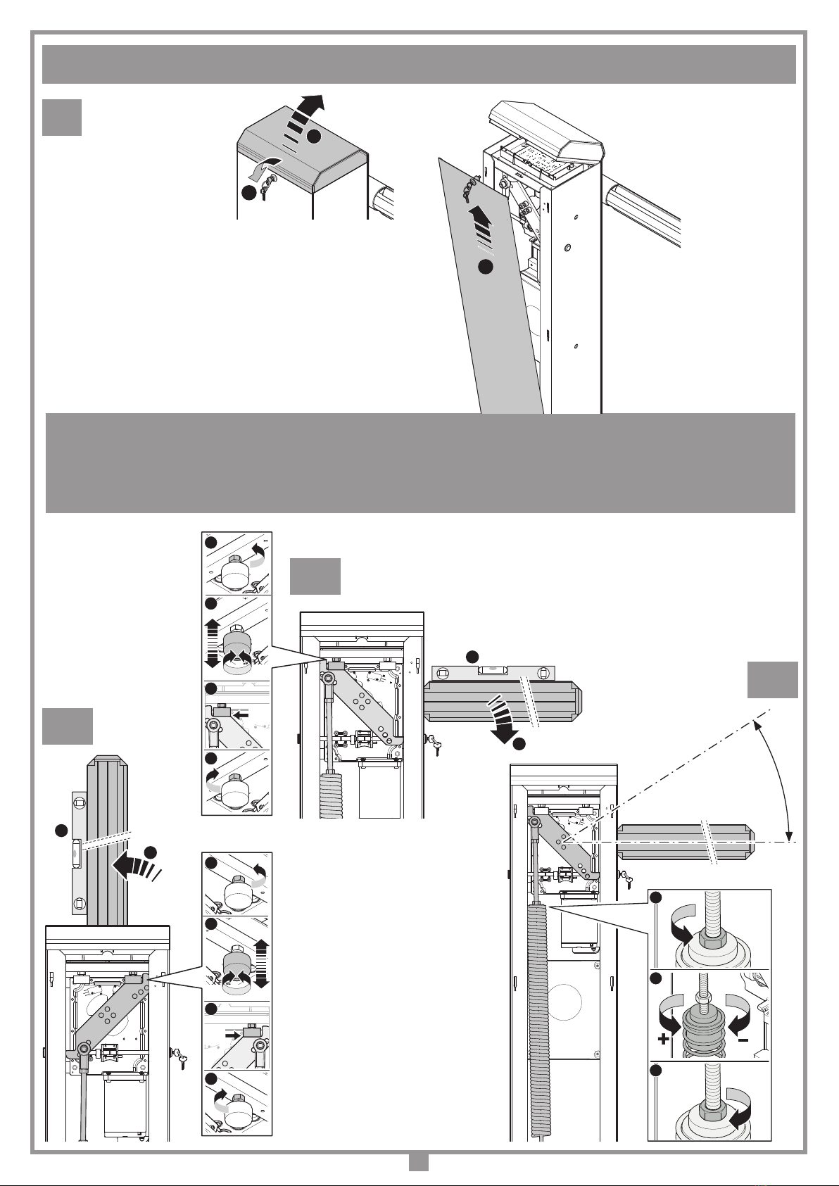
MOLLE DI BILANCIAMENTO ASTA
Per la configurazione della molla in base alla lunghezza e al peso dell'asta segue
la tabella sottostante. Il tipo di molla cambia con l'aggiunta di alcuni accessori
Cardin (ELUFS1, ELUFS1-ML, ELUMS1, ELSRS ecc.).
Attenzione! Solo per clienti dell’EU - Marcatura WEEE.
Il simbolo indica che il prodotto alla fine della propria vita utile deve
essere raccolto separatamente dagli altri rifiuti. L’utente dovrà
pertanto conferire l’apparecchiatura agli idonei centri di raccolta
differenziata dei rifiuti elettronici ed elettrici, oppure riconsegnarla al
rivenditore al momento dell’acquisto di una nuova apparecchiatura
di tipo equivalente, in ragione di uno a uno.
L’adeguata raccolta differenziata per l’avvio al riciclaggio, al trattamento e allo
smaltimento ambientalmente compatibile contribuisce ad evitare possibili effetti
negativi sull’ambiente e sulla salute e favorisce il riciclo dei materiali.
Lo smaltimento abusivo del prodotto da parte del detentore comporta
l’applicazione delle sanzioni amministrative previste dalla normativa vigente
nello Stato Comunitario di appartenenza.
• Il presente manuale si rivolge a persone abilitate all'installazione di "Apparecchi
utilizzatori di energia elettrica" e richiede una buona conoscenza della tecnica,
esercitata in forma professionale e della normativa vigente. I materiali usati devono
essere certificati e risultare idonei alle condizioni ambientali di installazione.
• Le operazioni di manutenzione devono essere eseguite da personale qualificato.
Prima di eseguire qualsiasi operazione di pulizia o di manutenzione, disinserire
l'apparecchiatura dalla rete di alimentazione elettrica e scollegare eventuali batterie.
• Le apparecchiature qui descritte dovranno essere destinate solo all'uso per il quale
sono state espressamente concepite: Il controllo del passaggio di veicoli con
selezione di passaggi da 3a 6 m di luce netta.
Attenzione! L'apparechiatura ha un peso totale di circa 60kg quindi qualsiasi
operazione di trasporto e/o messa in posa deve essere eseguita con l'ausilio di un
sistema di sollevamento meccanico.
• QuestoprodottoèstatoprogettatoefabbricatointuttelesuepartiacuradellaCardin
Elettronica la quale ne ha verificato la perfetta corrispondenza delle caratteristiche
con quelle richieste dalla normativa vigente.
L'utilizzo dei prodotti e la loro destinazione ad usi diversi da quelli previsti e/o
consigliati, non è stata sperimentata dal costruttore, pertanto i lavori eseguiti sono
sotto la completa responsabilità dell'installatore. Il costruttore non risponde qualora
l'impianto elettrico non risulti conforme alle norme vigenti ed in particolare qualora
il circuito di protezione (terra) non sia efficiente.
È responsabilità dell’installatore verificare le seguenti condizioni di sicurezza:
1) L’installazione deve essere sufficientemente lontana dalla strada in modo da non
costituire pericolo per la circolazione.
2) La barriera deve essere installata all’interno della proprietà e l'asta non deve
sconfinare su strada o zona pubblica.
3) L’ingresso motorizzato è principalmente adibito al passaggio di vetture. Dove
possibile installare per pedoni un ingresso separato.
4) I comandi (compresi quelli di emergenza) devono essere posti in vista, ad un'altezza
compresa tra 1,5 m e 1,8 m e ad una distanza minima di 1.83 m da qualsiasi parte
della barriera in movimento. Inoltre quelli installati all’esterno devono essere protetti
da una sicurezza tale da prevenire l’uso non autorizzato. Un pulsante di emergenza
a fungo 'STOP-RESET' deve essere posto in vista dell'automazione e non deve
permettere alla barriera di mettersi nuovamente in moto.
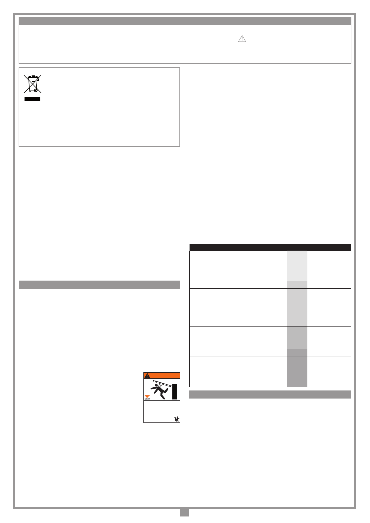
5) È buona norma segnalare l’automazione con targhe di avvertenza (simili a quella
in figura) che devono essere facilmente visibili. Qualora
l’automazione sia adibita al solo passaggio di veicoli dovranno
essere poste due targhe di avvertenza di divieto di transito
pedonale (una all’interno, una all’esterno).
6) Non permettere ai bambini di giocare con i comandi fissi del
dispositivo. Tenere i comandi a distanza lontano dai bambini.
Questo apparecchio non deve essere utilizzato da persone
(bambini compresi) con ridotte capacità fisiche, sensoriali o
mentali, oppure mancanza di esperienza o di conoscenza,
a meno che esse abbiano potuto beneficiare, attraverso
l’intermediazionediunapersona responsabile dellalorosicurezza,diuna sorveglianza
o di istruzioni riguardanti l’utilizzo dell’apparecchio.
7) A monte dell'automazione deve essere installato un dispositivo di sezionamento che
assicuriladisconnessioneonnipolaredallaretedialimentazione,conunadistanzadi
apertura dei contatti che consente la disconnessione completa nella condizioni della
sovratensione (categoria III), conformemente alle regole di installazione nazionale.
8) La bontà della connessione di terra dell’apparecchiatura è fondamentale ai fini della
sicurezza elettrica.
9) Prima di procedere all’installazione verificare che la temperatura ambiente sia
compresa nel range presente nella marcatura del dispositivo.
10) Per qualsiasi dubbio a riguardo della sicurezza dell’installazione, non procedere
ma rivolgersi al distributore del prodotto.
CONSIDERAZIONI GENERALI DI SICUREZZA
PERICOLO
La barriera stradale mobile può
causare lesioni gravi o la morte
• La barriera mobile potrebbe essere azionata senza
preavviso.
• Questa entrata è per soli veicoli. I pedoni sono tenuti
ad usare un’entrata separata.
• Le persone possono operare la barriera stradale solo
nel caso in cui la barriera è visibile e non ci sono
persone o ostacoli nelle vicinanze.
• Ai bambini è vietato operare la barriera o giocare
nella zona adiacente alla barriera stradale.
®
ATTENZIONE! IMPORTANTI ISTRUZIONI DI SICUREZZA
È IMPORTANTE PER LA SICUREZZA DELLE PERSONE SEGUIRE QUESTE ISTRUZIONI: LEGGERE ATTENTAMENTE LE SEGUENTI AVVERTENZE PRIMA DI
PROCEDERE ALL’INSTALLAZIONE. PRESTARE PARTICOLARE ATTENZIONE A TUTTE LE SEGNALAZIONI DISPOSTE NEL TESTO DI QUESTO LIBRETTO
D'ISTRUZIONI ORIGINALE. IL MANCATO RISPETTO DI QUESTE POTREBBE COMPROMETTERE IL BUON FUNZIONAMENTO DEL SISTEMA E CREARE
SITUAZIONI DI PERICOLO GRAVE PER L'OPERATORE E GLI UTILIZZATORI DEL SISTEMA STESSO. CONSERVARE QUESTE ISTRUZIONI PER OGNI FUTURO
RIFERIMENTO. LE ISTRUZIONI ORIGINALI ED EVENTUALI AGGIORNAMENTI SONO DISPONIBILI IN FORMATO DIGITALE NEL SITO WWW.CARDIN.IT.
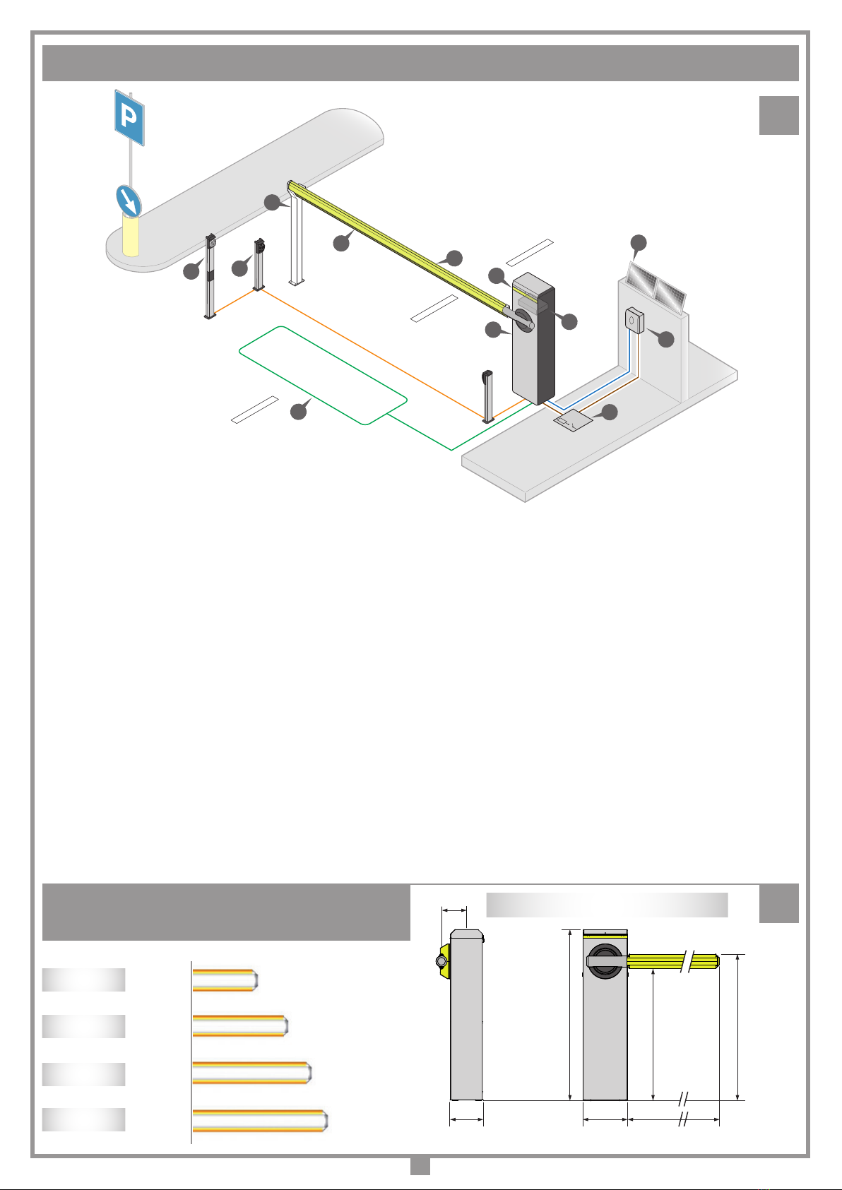
Aste + Accessori Metri Molla Colore N° molle
SNAPPER3 3 SP-YE Giallo 1
SNAPPER3 + ELUMS1 3 SP-YE Giallo 1
SNAPPER3 + SNR SNAP 3 SP-YE Giallo 1
SNAPPER3 + ELSRS 3 SP-YE Giallo 1
SNAPPER3 + ELSRS + ELUMS1 3 SP-GR Verde 1
SNAPPER4 4 SP-GR Verde 1
SNAPPER4 + ELUMS1 4 SP-GR Verde 1
SNAPPER4 + SNR SNAP 4 SP-GR Verde 1
SNAPPER4 + ELSRS 4 SP-GR Verde 1
SNAPPER4 + ELSRS + ELUMS1 4 SP-GR Verde 1
SNAPPER5 5 SP-RE Rosso 1
SNAPPER5 + ELUMS1 5 SP-RE Rosso 1
SNAPPER5 + ELSRS 5 SP-RE Rosso 1
SNAPPER5 + ELSRS + ELUMS1 5 SP-WH Bianco 1
SNAPPER6 6 SP-WH Bianco 1
SNAPPER6 + ELUMS1 6 SP-WH Bianco 1
SNAPPER6 + ELSRS 6 SP-WH Bianco 1
SNAPPER6 + ELSRS + ELUMS1 6 SP-WH Bianco 1
ISTRUZIONI PER L'INSTALLAZIONE
• L'installazione della barriera è possibile sia a sx che a dx della luce passaggio.
I comandi minimi che possono essere installati sono APERTURA-STOP-CHIUSURA,
tali comandi devono essere posti in un luogo non accessibile a bambini o minori.
Durante la manovra si deve controllare il movimento dell’asta e azionare il dispositivo
di arresto immediato (STOP) in caso di pericolo.
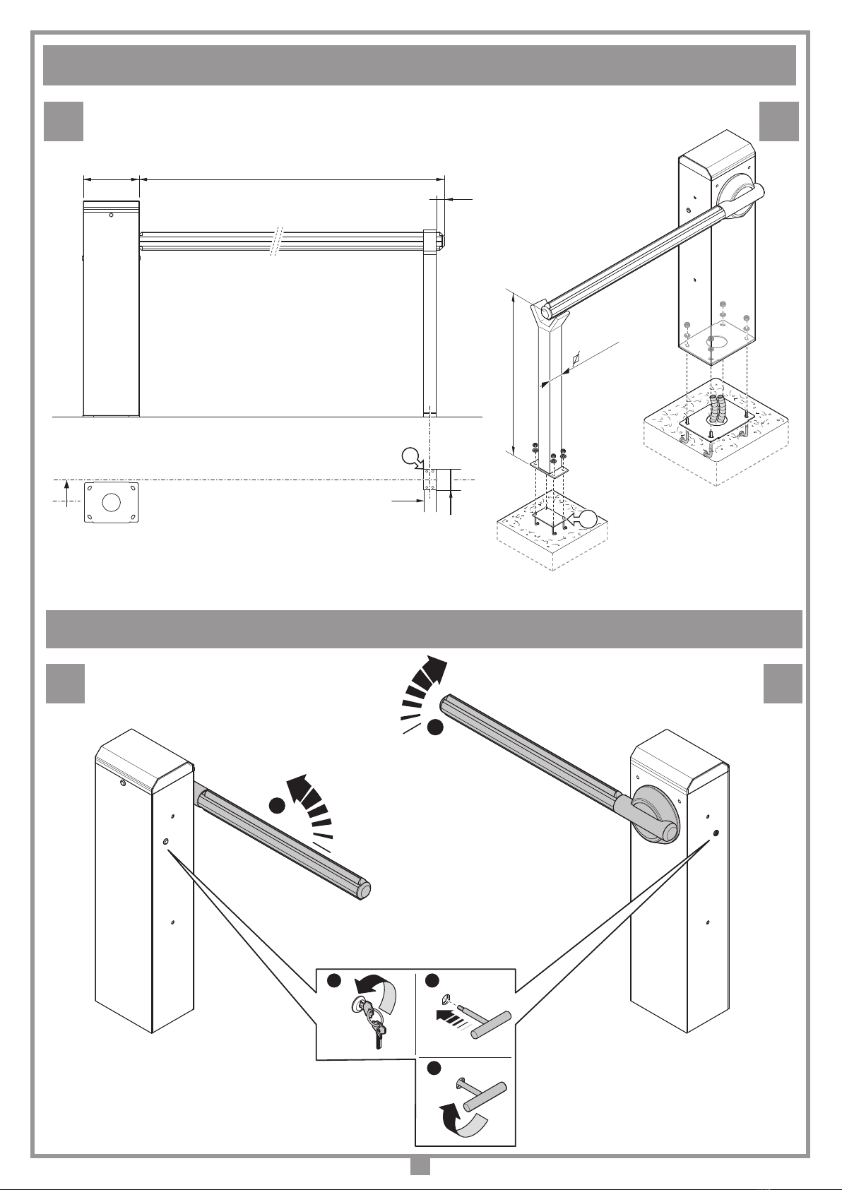
In caso di emergenza (arresto) l’asta può essere sbloccata manualmente (vedi
"manovra manuale" a pag. 9).
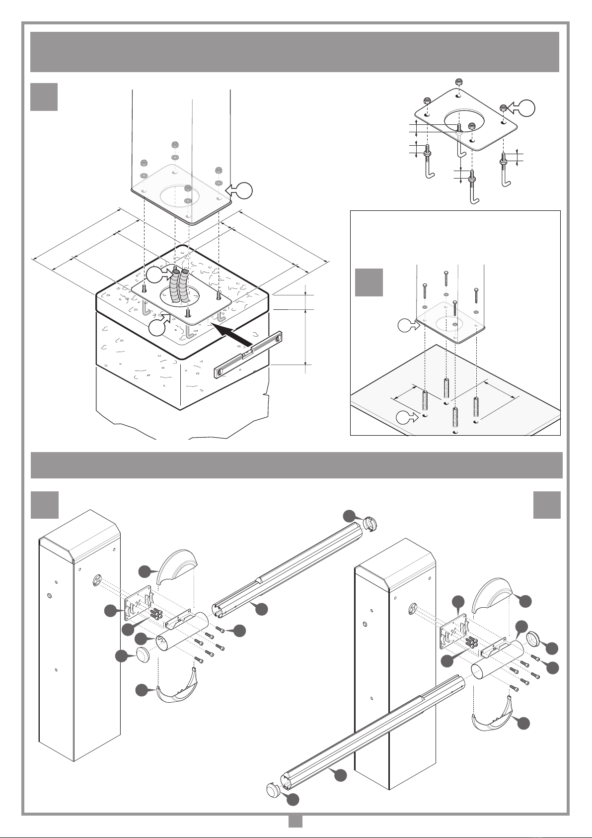
• Il terreno deve avere caratteristiche tali da garantire una sufficiente tenuta al plinto
di fondazione, in cui sarà inserita la piastra di base con relative zanche di fissaggio.
• Possibilmente proteggere il corpo barriera da urti accidentali da parte di veicoli
che transitano nei pressi della barriera.
• Assicurarsi che l’asta non si sposti verso oggetti rigidi situati a meno di 16 pollici
di distanza (406 mm) e che tutti i punti critici tra le parti mobili siano stati eliminati
o protetti.
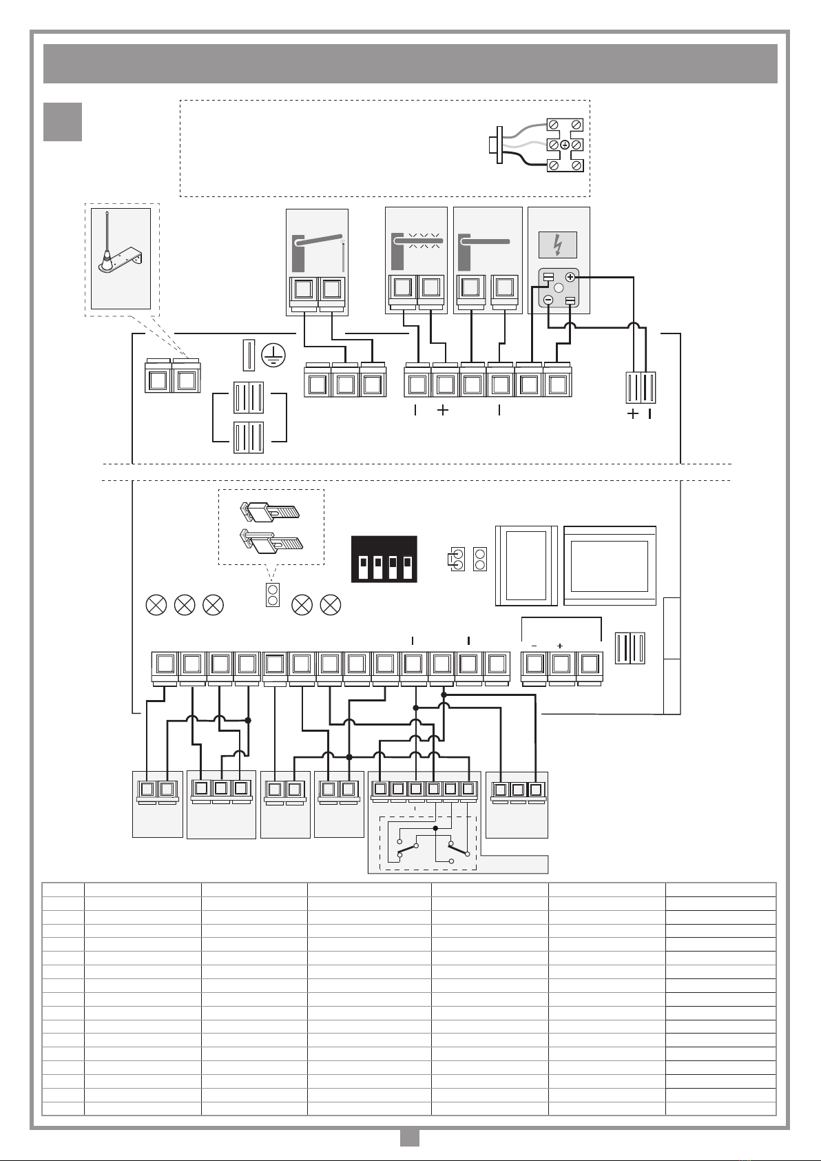
• Prevedere il percorso dei cavi secondo le necessità di applicazione dei dispositivi
di comando e sicurezza (ved. impianto tipo fig. 1 pag. 2).

9
MANOVRA MANUALE (fig. 8)
Attenzione! La manovra manuale va fatta solamente con apparecchiatura in
blocco, per mancanza di energia elettrica oppure durante la fase di installazione
dell'automazione.
L'accesso allo sblocco può essere a destra o a sinistra a seconda dell'installazione.
Per poter accedere al meccanismo è necessario ruotare la chiave come indicato
nella sequenza A(lasciare inserita la chiave) poi utilizzando la chiave esagonale
in dotazione (sequenza Be C) sbloccare il motore. Per ribloccare il motore agire
in senso contrario.
APERTURA MOBILETTO (fig. 9)
Per accedere alle regolazioni meccaniche / elettroniche mediante la chiave in
dotazione: girare la chiave in senso antiorario "1" e togliere il coperchio "2". Tirare
lo sportello "3" verso l'alto per rimuoverlo "4".
REGOLAZIONE MECCANICA DELLA POSIZIONE ORIZZONTALE /
VERTICALE DELL’ASTA (fig. 10-10a)
I finecorsa in gomma sono già regolati in posizione per l'apertura a 0° e 90°, non è
quindi necessaria la regolazione degli stessi se non si vogliono avere altre posizioni.
Vedi paragrafo "Programmazione posizione di apertura e chiusura".
Sbloccare l'asta e mandarla in battuta di chiusura "1". Sblocare il dado "2"
ruotandolo in senso antiorario, mettere la bolla "3" sull'asta ed agire sulla vite "4"
per aggiustare la posizione orizzontale. Trovata la posizione corretta "5" bloccare
il dado "6".
BILANCIAMENTO ASTA (fig. 10b)
Sbloccare l'asta, aprire lo sportello ed agire sul dado "1" ruotandolo in senso
antiorario (5 giri circa). Ruotare la molla in senso antiorario per aumentare la tensione
o in senzo orario per diminuire la tensione finchè l'asta rimanga in posizione "3"
inclinata di circa 30° - 40°. Trovato il bilanciamento ottimale, serrare il dado "4".
COLLEGAMENTO ELETTRICO
Avvertenze importanti
• La funzione del rilevamento di ostacolo non elimina l’obbligo di installare le
fotocellule o altri dispositivi di sicurezza previsti dalle normative vigenti.
• Accertarsi, prima di eseguire il collegamento elettrico, che la tensione e la
frequenza riportate sulla targhetta caratteristiche corrispondano a quelle
dell'impianto di alimentazione.
• Il cavo di alimentazione deve essere in gomma e del tipo 60245 IEC 57 (es.
3 x 1.5 mm2 H05RN-F).
• La sostituzione del cavo d'alimentazione deve essere eseguita da personale
qualificato.
• Tra la centralina di comando e la rete deve essere interposto un interruttore
onnipolare, con distanza di apertura tra i contatti di almeno 3 mm.
• Non utilizzare cavo con conduttori in alluminio; non stagnare l’estremità dei
cavi da inserire in morsettiera; utilizzare cavo con marcatura T min 85°C
resistente agli agenti atmosferici.
• I conduttori dovranno essere adeguatamente fissati in prossimità della
morsettiera in modo che tale fissaggio serri sia l’isolamento che il conduttore.
• Collegare i fili di comando e quelli provenienti dalle sicurezze.
• Portare l'alimentazione generale alla morsettiera separata a tre vie passando
prima attraverso il pressacavo:
- collegare il neutro al morsetto N
- collegare la terra al morsetto
- collegare la fase al morsetto L
È importante la buona riuscita del fissaggio alla base della barriera in
quanto, col tempo ed un utilizzo intensivo, si potrebbero avere allentamenti
degli ancoraggi a terra con ripercussione deleteria sulle oscillazioni di tutto
il mobiletto e dell’asta.
FISSAGGIO DEL DISPOSITIVO CONTROBASE (fig. 3/3a)
Preparare una piazzola in cemento in cui sia inserita la piastra di base "C" (opzionale),
con annesse le zanche di ancoraggio, da cui dovranno emergere le condutture per
il passaggio dei cavi elettrici "D", utilizzando l’apposita apertura, e quattro gambi
filettati M12, sporgenti 30 mm. La piastra dovrà risultare perfettamente in bolla,
pulita in tutta la sua superficie e con i filetti
M12 emergenti perpendicolarmente
dalla piastra e perfettamente puliti.
Note: È preferibile che la piazzola sporga dal livello terra di circa 50 mm, questo
per evitare che accumuli d’acqua possano danneggiare l’apparecchiatura.
Le dimensioni del plinto di fondazione variano in funzione della natura del suolo.
Svitare i quattro dadi autobloccanti "F" sui quattro gambi filettati (utilizzati per
bloccare le zanche) e inserirvi la base "E" della barriera. Quindi fissarla tramite i
quattro dadi autobloccanti "F" e relative rondelle in dotazione.
È anche possibile fissare la base della barriera ad una pavimentazione in cemento
già esistente purché lo spessore della pavimentazione sia tale da garantire la presa
del tassello e sia di buona fattura.
Tassello consigliato: "Ancorante in acciaio M12/Ø20 per fissaggi pesanti".
INSTALLAZIONE ASTA (fig. 4-5)
Montare la base di fissaggio asta "A" e bloccare con le viti in dotazione "H"
applicando una coppia di chiusura superiore a 70 Nm. Applicare la porta asta "B"
e bloccarla con le viti "F". Inserire il preassiemato asta "G" nella porta asta "B".
Fissare l'asta completa alla base "A" e serrare le viti "F". Inserire i tappi "C" ed
"I". Applicare i semilunari del comprimozzo "E eD" spingendo fino a bloccarli in
posizione.
INSTALLAZIONE MOLLA (fig. 6)
Per le versioni EL SNAPS ed EL SNAPL prima installare la molla acquistata con
la barriera. Quindi applicare un po' di grasso sulla barra filettata "B", completa di
dado di bloccaggio "C" e testina snodata, ed avvitarlo in senso orario nella parte
superiore della molla (indicato dal colore).
Applicare un po' di grasso sul tirante di gancio "D" ed avvitarlo alcuni giri in senso
antiorario nella parte inferiore non colorato della molla "A".
Agganciare l’assieme molla "A" così ottenuto con il gancio alla parte inferiore
dell’armadio "F", fissare la testina alla bilanciere "G" utilizando il dado e bullone
"E". Utilizzare in prima fase il foro più esterno, se successivamente si verifica che
la molla è troppo forte per il bilanciamento dell’asta, utilizzare man mano i fori
più all’interno. Avvitare la barra filettata "B" per bilanciare il sistema asta-molla e
bloccare la barra in posizione con il dado "C". Serrare il bullone "E" con una coppia
di almeno 85-90 Nm.
INVERSIONE APERTURA ASTA SNAP RAPID (fig. 6a-6e)
Per invertire il senso d'apertura asta da sinistra (fig. 6a) a destra (fig. 6e), sbloccare
l'asta e portarla in posizione verticale "A" fig. 6b. Con la molla "C" in posizione di
riposo (NON SOTTO TENSIONE) svitare e togliere il bullone e dado "B". Rimuovere
la molla. Smontare e rimontare l'asta a destra figura 5 e portarla in posizione verticale
"A" (fig 6c). Rimontare la molla "C" ed inserire e serrare il bullone e dado "B" (fig.
6d). Ribloccare l'asta e selezionare l'installazione asta "destra" spostando il dip
N°7 in ON (fig 12), eseguire la programmazione iniziale della centralina (pag. 12).
MONTAGGIO DELL’APPOGGIO FISSO (fig. 7-7a)
L'appoggio fisso va posizionato in punta d'asta, e rappresenta un punto riferimento
alla chiusura dell'asta. L'asta durante la manovra non dovrà mai urtare ma si dovrà
posare delicatamente al piano d'appoggio.
Preparare una piazzola in cemento in cui sia inserita la piastra di base "S", con
annesse le zanche di ancoraggio, da cui dovranno emergere quattro gambi filettati
M8, sporgenti 30 mm.
La piastra dovrà risultare perfettamente in bolla, pulita in tutta la sua superficie e
con i filetti M8 emergenti perpendicolarmente dalla piastra e perfettamente puliti.
Svitare i quattro dadi autobloccanti sui quattro gambi filettati (utilizzati per bloccare
le zanche fig. 7a) e inserirvi la base dell'appoggio. Quindi fissarla tramite i quattro
dadi e relative rondelle in dotazione.
È anche possibile fissare la base dell'appoggio ad una pavimentazione in cemento
già esistente purché lo spessore della pavimentazione sia tale da garantire la presa
del tassello e sia di buona fattura.
Tassello consigliato: "Ancorante in acciaio M8/Ø14 per fissaggi pesanti".
N
L
Fissaggio placca inferiore
06-03-95
DI0286 Description :
Product Code :
Date :
Drawing number :
P.J.Heath
CARDIN ELETTRONICA S.p.A - 31020 San Vendemiano (TV) Italy - via Raffaello, 36 Tel: 0438/401818 Fax: 0438/401831
Draft :
All rights reserved. Unauthorised copying or use of the information contained in this document is punishable by law
Collegamento motore

10
Collegamenti morsettiera
1-2 TPR segnalazione assenza linea. Collegare il secondario del
trasformatore.
3-4 SLAVE uscita comando slave. Collegare la centralina della seconda
barriera.
5-6 LDA uscita LED asta 24 Vdc 100 mA. Collegare a le luci asta se
presenti.
7-8 US1 (N.C.) uscita contatto Jolly (max. 8A 230V)
8-9 US1 (N.A.) uscita contatto Jolly (max. 8A 230V)
10 Massa antenna ricevitore radio
11 Centraleantenna ricevitore radio (nelcaso si utilizzi un’antenna esterna
collegarla con cavo coassiale RG58 imp. 50Ω)
12 TD (N.A.) ingresso pulsante comando sequenziale
13 TA (N.A.) ingresso pulsante di apertura
14 TC (N.A.) ingresso pulsante di chiusura
15 CMN comune per tutti gli ingressi/uscite
16 CC (N.C./8.2 kΩ)ingresso per costa sensibile in chiusura. L'apertura
del contatto inverte il moto di qualche grado nella fase di chiusura.
Jumper J4 pos. 2 = contatto N.C. Jumper J4 pos. 1 = contatto 8.2
kΩ. Se non viene utilizzato portare il dip 3 CC in On (DS2)
17 TB (N.C.) ingresso pulsante di blocco (all’apertura del contatto si
interrompe il ciclo di lavoro fino ad un nuovo comando di moto). Se
non viene utilizzato portare il dip 2 TB in On (DS2)
18 FT (N.C.) ingresso per dispositivi di sicurezza (fotocellula di inversione
in chiusura). L’apertura del contatto, conseguente all’intervento dei
dispositivi di sicurezza, durante la fase di chiusura, attuerà l’inversione
del moto. Se non viene utilizzato portare il dip 1 FT in On (DS2)
19 BSP (N.C.) ingresso blocco sicurezza porta. L’apertura del contatto
interrompe il ciclo di lavoro fino alla chiusura della porta. Attualmente
non presente. Se viene installato tagliare il ponticello J5 e collegare
questo ingresso al microinterruttore di sicurezza sulla porta.
24V IN Ingresso 24V alimentazione centralina
DS1 Dip-switch di esclusione sicurezze
DS2 Dip-switch di selezione funzioni
FC1 Finecorsa 1
FC2 Finecorsa 2
F1 Fusibile tubicino 12,5A ritardato protezione alimentazione motore
F2 Fusibile tubicino 2A protezione circuito 24V
J1 Jumper di selezione modalità sequenziale canale 1 ricevitore OC
J2 Jumper di selezione modalità apertura canale 1 ricevitore OC
J3 Jumper RESET centralina
J4 Jumper di selezione N.C./8.2 kΩ
J5 Jumper (ponticellato) esclusione microinterrutore porta
J6 Jumper Test. Rimuovere questa jumper Pos. 2 per abilitare il controllo
dell'uscita CTRL24Vdc
MOT Connessione motore 24V
OC Modulo RF open collector, 433 / 868 MHz
P1 Tasto PROG/STOP
P2 Tasto sequenziale TD
P3 Tasto programmazione
SL1 Connettore luci led interne
SL2 Connettore luci led interne
T1 Trimmer di regolazione rallentamento in apertura
20 CSB comune per gli ingressi di sicurezze
21-22 Uscita alimentazione fotocellule CTRL24Vdc. Tensione presente solo
quando l'asta non è chiusa.
23-24 Uscita alimentazione dispositivi ausiliari 24Vdc. Questo contatto è
sempre alimentato.
25-27 ENCODER ingressi segnali encoder - / + / data per segnali encoder
TUTTI I CONTATTI N.C. NON UTILIZZATI VANNO PONTICELLATI
• Alimentare il circuito e verificare che lo stato dei LED di segnalazione sia
il seguente:
- L1 Led di programmazione spento
- L2 Led di segnalazione finecorsa di apertura
(FC1)
spento/acceso*
- L3 Led di segnalazione finecorsa di chiusura
(FC2)
spento/acceso*
- L4 Led di segnalazione
fotocellulla di inversione (FT)
acceso
- L5 Led di segnalazione
tasto di blocco (TB)
acceso
- L6 Led di segnalazione
tasto di chiusura (TC)
spento
- L7 Led di segnalazione
tasto di apertura (TA)
spento
- L8 Led di segnalazione comando sequenziale (TD/CH1) spento
Nel caso in cui nessun LED si accenda verificare lo stato dei fusibili ed il
collegamento del cavo di alimentazione al primario del trasformatore.
Nel caso in cui uno dei led di segnalazione di sicurezza è spenta significa
che la sicurezza è intervenuta.
* dipende dalla posizione dell'asta.
Centrale di comando
PRG SNAP
05-07-2019
Description :
Product Code :
Date :
Drawing number :
P.J.Heath
CARDIN ELETTRONICA S.p.A - 31020 San Vendemiano (TV) Italy - via Raffaello, 36 Tel: 0438/401818 Fax: 0438/401831
Draft :
All rights reserved. Unauthorised copying or use of the information contained in this document is punishable by law
DC0595
PRG SNAP
CS19705 DC0595
P1 P2
L1
ANT
OC
+
T1
1 2 3 4
F1
F2
5 6 789
MOT
24V IN
FC1
FC2
10 11
(R)
(N)
25 26 27
19 20 21 22 23 24
16 17 18
15
12 13 14
P3
TC
TA
TD
NO
NO
NO
CMN
TB
CC
FT
BSP
NC
NC
NC
NC
CSB
CTRL24Vdc
24Vdc
L8
L7
L6
L3
L2
US1
LDA
NC
NO
CMN
D
D
SLAVE
TPR
L5
L4
1 2 3 4 5 6 7 8 910 11 12
ON
DS1
1 2 3 4
ON
DS2
FT
TB
CC
TPR
J1
J2
J3
J4
Gr Bl
ENCODER
Wh
J5
J6
SL1
SL2
TD
REG.VEL.
PRELAMP.
RIC. AUT.
INV.
SLAVE
US1
TPR
FOTORIC.
Pos.1
8,2K NC
Pos.2
Pos.1
CTRL24
Pos.2
DIS.
12

11
Descrizione Stato dip Funzione Note
Modo ingresso TD
(tasto dinamico - passo
passo) e canale radio
CH1
Dip 1
OFF Dip 2
OFF Apre -Stop-Chiude Durante l'apertura premendo il tasto TD la barriera si blocca, premendo nuovamente chiude.
Durante la chiusura premendo il tasto TD la barriera si blocca, premendo nuovamente apre.
Dip 1
ON Dip 2
OFF Apre-Chiude Durante l'apertura premendo il tasto TD la barriera si blocca e poi chiude.
Durante l'apertura premendo il tasto TD la barriera si blocca e poi apre.
Dip 1
OFF Dip 2
ON Apre sempre Premendo il tasto TD durante l'apertura o durante la pausa non ha alcun effetto.
Premendo il tasto TD durante la chiusura la barriera si blocca per alcuni secondi e poi apre.
Dip 1
ON Dip 2
ON Apre-Chiude con inversione
esclusa durante l'apertura
Premendo il tasto TD durante l'apertura non ha alcun effetto. Premendo il tasto TD durante la pausa la
barriera si chiude. Premendo il tasto TD durante la chiusura la barriera si blocca per alcuni secondi e poi apre.
Velocità della barriera
(SNAPS - SNAPL)
Dip 3
OFF Dip 4
OFF Velocità alta Tempo di apertura circa 3 secondi.
Dip 3
ON Dip 4
OFF Velocità medio-alta Tempo di apertura circa 4 secondi.
Dip 3
OFF Dip 4
ON Velocità medio-bassa Tempo di apertura circa 6 secondi.
Dip 3
ON Dip 4
ON Velocità bassa Tempo di apertura circa 8 secondi.
Prelampeggio
Dip 5
OFF - Escluso Il lampeggiante viene alimentato contemporaneamente al motore.
Dip 5
ON - Inserito Il lampeggiante viene alimentato 5 secondi prima di ogni manovra.
Timer richiusura
Dip 6
OFF - Escluso Dopo una apertura completa la centrale richiude solo con un comando manuale.
Dip 6
ON - Inserito Dopo una apertura completa la centrale richiude dopo il tempo di pausa programmato.
Inversione apertura
asta
Dip 7
OFF - Apertura sinistra Obligatorio eseguire la programmazione iniziale vedi pagina 12
Dip 7
ON - Apertura destra Obligatorio eseguire la programmazione iniziale vedi pagina 12
Funzionamento Slave
Dip 8
OFF - Escluso -
Dip 8
ON - Inserito La centrale esegue i comandi ricevuti dalla centrale Master.
Modo uscita US1 (jolly)
contatto puro
Dip 9
OFF Dip 10
OFF Contatto per luce di cortesia Accesa da inizio ciclo a un tempo programmabile dopo la chiusura.
Dip 9
ON Dip 10
OFF Contatto per lampeggiante Controllo per un lampeggiante con frequenza 2 Hz.
Dip 9
OFF Dip 10
ON Contatto per il ventoso
elettromagnetico Uscita attiva in apertura, pausa e chiusura.
Dip 9
ON Dip 10
ON Contatto di segnalazione
stato barriera Uscita attiva con barriera non chiusa.
Apertura per Blackout
Dip 11
OFF - Esclusa -
Dip 11
ON - Inserita Durante il Blackout la barriera rimane aperta. Con il ripristino della rete la barriera chiude se dip 6 è in
posizione ON.
Fotorichiusura
Dip 12
OFF - Esclusa -
Dip 12
ON - Inserita La fotocellula riduce il tempo di pausa, qualunque sia stato il suo valore, a 2 secondi.
CONFIGURAZIONE DIP-SWITCH DI SELEZIONE FUNZIONI DS1
CONFIGURAZIONE DIP-SWITCH DI SELEZIONE FUNZIONI DS2
Descrizione Stato dip Funzione Note
Controllo ingresso
fotocellula FT
Dip 1
OFF - Attivo Ingresso FT attivo (una fotocellula deve essere collegata tra i contatti 18-20).
Dip 1
ON - Escluso Esclude l'ingresso FT (non è necessario ponticellare i contatti 18-20).
Controllo ingresso
tasto di blocco TB
Dip 2
OFF - Attivo Ingresso TB attivo (un tasto di blocco deve essere collegato tra i contatti 17-20).
Dip 2
ON - Escluso Esclude l'ingresso TB (non è necessario ponticellare i contatti 17-20).
Controllo ingresso
costa di sicurezza CC
Dip 3
OFF - Attivo Ingresso CC attivo (contatto 8,2K con jumper J4 in pos. 1 - contatto NC con jumper J4 in pos. 1
Dip 3
ON - Escluso Esclude l'ingresso CC (non è necessario ponticellare i contatti 16-20).
Segnalazione assenza
rete TPR
Dip 4
OFF - Inserito Collegare il secondario del trasformatore ai morsetti 1 e 2. Se manca la tensione di rete la barriera apre (con il
dip 11 in posizione ON e batterie opzionali collegate).
Dip 4
ON - Escluso Esclude l'ingresso TPR (non è necessario ponticellare i contatti 1-2).

12
PROGRAMMAZIONE POSIZIONE DI APERTURA E CHIUSURA
La barriera ELSNAP è programmata in fabbrica con il punto completamente
aperto standard a 90 gradi e completamente chiuso a 0 gradi. Se necessita
un punto di apertura/chiusura diverso dallo standard procedere come segue:
Per il punto di apertura:
- togliere alimentazione alla centralina;
- portare in posizione OFF il dip 6 di richiusura automatica;
- allentare il controdado e alzare provvisoriamente il gommino antivibrante di
apertura (g. 10);
- ridare alimentazione alla centralina;
- premere il pulsante P2 per aprire l'asta;
- premere e tenere premuto il pulsante P1 per circa 3 sec. nché il Led L1 si
accende;
- premere più volte P2 per spostare il punto in apertura oppure P3 per spo-
starlo verso la chiusura;
- premere P1 per memorizzare il punto scelto;
- togliere alimentazione alla centralina;
- portare il gommino antivibrante in appoggio al bilancino (g. 10);
- sbloccare l’asta e portarla al punto di equilibrio (circa 45 gradi);
- abbassare ancora il gommino antivibrante di circa 2 millimetri e bloccarlo
con il controdado;
- riportare il dip 6 in posizione ON per riabilitare la richiusura automatica;
- ridare alimentazione alla centrale.
Per il punto di chiusura:
- premere il pulsante P2 per aprire l'asta;
- togliere alimentazione alla centralina;
- portare in posizione OFF il dip 6 di richiusura automatica;
- allentare il controdado e alzare provvisoriamente il gommino antivibrante di
chiusura (g. 10);
- dare alimentazione alla centralina;
- premere il pulsante P2 per chiudere l'asta;
- premere e tenere premuto il pulsante P1 per circa 3 sec. nché il Led L1 si
accende;
- premere più volte P2 per spostare il punto in apertura oppure P3 per spo-
starlo verso la chiusura;
- premere P1 per memorizzare il punto scelto;
- togliere alimentazione alla centralina;
- portare il gommino antivibrante in appoggio al bilancino (g. 10);
- sbloccare l’asta e portarla al punto di equilibrio (circa 45 gradi);
- abbassare ancora il gommino antivibrante di circa 2 millimetri e bloccarlo
con il controdado;
- riportare il dip 6 in posizione ON per riabilitare la richiusura automatica;
- ridare alimentazione alla centrale.
PROGRAMMAZIONE TEMPO DI PAUSA
Questa operazione va fatta con la barriera chiusa:
- premeree tenerepremutoilpulsanteP3nchésiaccendeilLedL1 (lampeggio
una volta per secondo);
- premere P2 per far partire il conteggio del tempo di pausa. Il Led L1 cambia
il tipo di lampeggio;
- trascorso il tempo di pausa desiderato, premere di nuovo il pulsante P2 per
memorizzarlo. Il Led L1 rimarrà acceso sso per un paio di secondi, poi si
spegne.
PROGRAMMAZIONE TEMPO LUCE DI CORTESIA
Morsetti 7/8/9 con dip 9 e 10 in posizione OFF
Questa operazione va fatta con la barriera chiusa:
- premere etenere premuto ilpulsante P3 nchésiaccende il Led L1 lampeggio
una volta per secondo;
- premere nuovamente P3, il Led L1 ora lampeggerà due volte per secondo;
- premere P2 per far partire il conteggio del tempo della luce di cortesia. Il
Led L1 cambia tipo di lampeggio.
- trascorso il tempo di pausa desiderato, premere di nuovo il pulsante P2 per
memorizzarlo. Il Led L1 rimarrà acceso sso per un paio di secondi, poi si
spegne.
VISUALIZZAZIONE DEL NUMERO DI MANOVRE TOTALE
Questa operazione va fatta con la barriera chiusa:
- premere e tenere premuto il pulsante P3 ed inserire e togliere il jumper J3
per resettare la centralina;
- i led gialli interni lampeggeranno per 6 volte, dopodiché inizierà la
visualizzazione del numero delle manovre;
- la visualizzazione avviene come segue.
• Prima cifra: numero di lampeggi dei led rossi e gialli assieme (centinaia di
migliaia).
• Seconda cifra: numero di lampeggi dei led gialli (decine di migliaia)
• Terza cifra: numero di lampeggi dei led rossi (migliaia)
Esempio: visualizzazione di 210.000 cicli di lavoro:
- led rossi e gialli lampeggiano 2 volte;
- pausa;
- led gialli lampeggiano una volta;
- pausa;
- led rossi non lampeggiano;
- ne.
PROGRAMMAZIONE DELL'ALLARME MANUTENZIONE
La centrale SN24 segnala l’allarme manutenzione tramite 6 lampeggi dei Led
rossi interni.
Il numero dei cicli, dopo i quali viene segnalato l’allarme, è programmato da
fabbrica a 100.000. Per modicare questo parametro procedere come segue:
- ad asta chiusa premere P1 per circa 10 secondi (dopo tre secondi L1 si
accende, tenere premuto nché L1 si spegne di nuovo);
- ora l’allarme manutenzione è stato cancellato, quindi bisogna reimpostarlo.
- il numero viene impostato a multipli di 10.000, premere P2 per aumentare i
lampeggi del Led L1 (il numero massimo di lampeggi è 10 che corrisponde
a 100.000 manovre);
- premere il tasto P3 per memorizzare il numero impostato.
BARRIERE CONTRAPPOSTE, FUNZIONE MASTER-SLAVE
Con questo modo d’installazione è possibile avere due barriere contrapposte
che si muovono in sincronia tra loro:
- installare le due barriere eseguendo, se necessario, le regolazioni delle
posizioni di apertura e di chiusura.
- sceglierelabarrieraprincipale(MASTER)percollegareinessatuttelefunzioni
dell’impianto (comandi, ricevitori radio, sicurezze, fotocellule, ecc.);
- sulla barriera secondaria (SLAVE) lasciare tutto come da fabbrica. Collegare
solamente la costa, se presente. Mettere il dip 8 in posizione ON ed inserire
e togliere il jumper J3 per resettare la centralina;
- collegare l’uscita Slave della barriera MASTER al morsetto 12 “TD” della
barriera SLAVE.
- collegare il morsetto 3“-” della MASTER al morsetto 15 “CMN” della SLAVE;
- collegare il morsetto 4“D” della MASTER al morsetto 12 “TD” della SLAVE;
- se il collegamento è corretto, il led corrispondente all’ingresso “TD” della
barriera SLAVE inizia a lampeggiare;
- collegare il morsetto 4“D” della barriera SLAVE al morsetto 13 “TA” della
barriera MASTER;
- testare l’impianto provando i vari comandi e le sicurezze delle due barriere.
PROGRAMMAZIONE INIZIALE DELLA CENTRALINA
Questa procedura è necessaria se viene sostituita la centrale SN24 alla bar-
riera SNAP e dopo aver eseguito l'inversione apertura asta (vedi. g. 6a-6e).
Dopo questa operazione proseguire con la regolazione dei punti di apertura
e di chiusura, se necessario.
- effettuare un reset inserendo jumper J3 e premendo i pulsanti P3 e P1
simultaneamente. Rilasciare i pulsanti all’accensione del Led L1;
- premere il pulsante P2. La barriera effettuerà una serie di movimenti no a
fermarsi in chiusura;
- lo spegnimento del led L1 indica la ne della procedura.
SEGNALAZIONI DI ERRORI
La barriera segnala eventuali anomalie attraverso il lampeggio dei led rossi
presenti nei due lati dell’armadio:
N° di lampeggi Significato Descrizione
1 allarme costa costa premuta o guasto ai collegamenti elettrici
2 asta forzata con asta chiusa, segnala la forzatura manuale
3intervento
encoder rilevazione ostacolo
4 encoder assente encoder guasto/collegamento errato/guasto F1
5 anomalia mosfet guasto driver del controllo motore
6allarme
manutenzione superamento del numero manovre impostato
7 errore necorsa guasto dei necorsa elettrici o collegamento errato

13
FUNZIONAMENTO A BATTERIA
Le barriere,predisposteper l’inserimentodibatteriein tampone,possonofunzionare
con SUN POWER per applicazioni isolate dove non arriva la rete elettrica .
Perl'installazioneefunzionalitàabatteriaconsultareillibrettod’istruzioniZVL650fornito
con la scheda caricabatteria CB24 ed il libretto d’istruzioni ZVLISTSUNPOWER fornito
con il KIT SUNPOWER.
MANUTENZIONE
Attenzione! Prima di eseguire qualsiasi operazione di pulizia o di manutenzione,
disinserire l’apparecchiatura dalla rete di alimentazione elettrica, staccare
l’alimentazione del motore e scollegare le batterie (se presenti).
Le eventuali riparazioni devono essere eseguite da personale specializzato usando
materiali originali e certificati.
Il motore normalmente non necessita di particolari manutenzioni; in ogni caso la
garanzia fornita per 24 mesi o di 1 milione di manovre ha validità a condizione
che vengono effettuati i seguenti controlli ed eventuali interventi sulla macchina
‘barriera stradale’:
- controllare periodicamente lo stato di usura dei perni ed eventualmente
ingrassare le parti in moto usando lubrificanti che mantengano uguali
caratteristiche di attrito nel tempo e adatti a funzionare tra -20 e +70°C;
- verificare periodicamente il funzionamento delle sicurezze (fotocellule, coste
sensibili ecc.);
- verificare il livello di carica delle batterie.
Dette verifiche devono essere documentate in quanto sono indispensabili per
usufruire della garanzia come stipulate nelle Condizioni di Vendita Generale della
Cardin Elettronica.

14
ATTENZIONE! IMPORTANTI ISTRUZIONI DI SICUREZZA
Have the appliance controlled and checked at regular intervals by specialised
maintenance personnel:
- Check to be carried out after the rst 200.000 manoeuvres (or six months after
the installation);
Periodically check the correct operation of all safety devices (photoelectric cells etc.).
Frequently examine the installation for imbalance where applicable and signs of wear
or damage to cables, springs and mounting.
Eventual repair work or maintenance must be carried out by specialised personnel
using original spare parts. The appliance is not suitable for continuous operation
and must be adjusted according to the model (see technical data on page 48).
TECHNICAL DESCRIPTION
Automation for 3 m to 6 m booms with a 24 Vdc motor.
• Encoder-controlled movement.
• Robust, rapid opening road barrier designed to last through time, complete with
boom holder, warning lights built in to the hood and an external Allen key operated
release system.
• The “master/slave” function allows you to synchronise two barriers working in
unison.
• The incorporated electronic programmer contains the power stage and the logic
control (optional radio receiver module).
• Boom balancing spring included in the version EL SNAP-RAPID. To be ordered
apart for the other versions.
BOOM BALANCING SPRINGS
For the custom t springs according to the length and weight of the boom consult
the table below. The type and number of springs varies when some of the Cardin
(ELUFS1, ELUFS1-ML, ELUMS1, ELSRS etc.) accessories are added.
Attention!
Only for EU customers
- WEEE marking
This symbol indicates that once the products life-span has expired
it must be disposed of separately from other rubbish. The user is
therefore obliged to either take the product to a suitable differential
collection site for electronic and electrical goods or to send it
back to the manufacturer if the intention is to replace it with a
new equivalent version of the same product.
Suitable differential collection, environmental friendly treatment and disposal
contributes to avoiding negative effects on the ambient and consequently
health as well as favouring the recycling of materials.
Illicitly disposing of this product by the owner is punishable by law and will
be dealt with according to the laws and standards of the individual member
nation.
• These instructions are aimed at professionally qualied "Installers of electrical
equipment" and must respect the local standards and regulations in force.
All materials used must be approved and must suit the environment in which the
installation is situated.
• All maintenance operations must be carried out by professionally qualied technicians.
Before carrying out any cleaning or maintenance operations make sure the power is
disconnected at the mains and any batteries have been disconnected.
• This appliance must be used exclusively for the purpose for which it has been made.
"i.e. for traffic control" of passageways with widths of 3to 6 m.
Attention!The appliance has a total weight of about 60 kg therefore you must use
mechanical lifting equipment when transporting or installing.
• This product and all its relative components has been designed and manufactured
by Cardin Elettronica that has veried that the product conforms in every aspect to
the safety standards in force. Any non authorised modications are to be considered
improper and therefore dangerous.
The manufacturer accepts no liability for situations arising from the use of an electrical
installation which does not conform to the local standards and regulations in force
and in particular when the earthing circuit is not efcient.
IMPORTANT SAFETY INSTRUCTIONS
It is the responsibility of the installer to make sure that the following public safety conditions
are satised:
1) Ensure that the barrier installation is far enough away from the main road to eliminate
possible trafc disruptions.
2) The barrier must be installed on the inside of the property and not on the public side
of the property. The booms must not swing outwards onto a public area.
3) The barrier is designed for use on installations through which vehicles are passing.
Pedestrians should use a separate entrance.
4) The controls (including emergency commands) must be installed at a height between
1,5 and 1,8 m and at a minimum distance of 1.83 m (6 ft) from any moving part of the
barrier. Controls installed externally must be protected by a safety device inhibiting
unauthorised use. An emergency button 'STOP-RESET' must be installed within
sight of the automatic system and when active must not permit the barrier to move
again.
5) At least two warning signs (similar to the example on the right) should
be placed, where they can be easily seen by the public, in the area of
the system of automatic operation. One inside the property and one
on the public side of the installation. These signs must be indelible
and not hidden by any objects (such as tree branches, decorative
fencing etc.).
6) Do not allow children to play with xed controls and keep remote
controls away from them. This appliance can be used by children
aged from 8 years and above and persons with reduced physical, sensory or mental
capabilities or lack of experience and knowledge if they have been given supervision or
instruction concerning use of the appliance in a safe way and understand the hazards
involved.
7) Ahead of the automation a means of disconnection from the power supply must be
installed which has an opening distance on the contacts of all the poles and ensures
that the power supply is completely cut off under the conditions of a category III over
voltage situation.
8) A correct earth connection is fundamental in order to guarantee the electrical safety of
the machine
9) Before installingmake sure that theambient temperature falls withinthe range indicated
on the appliance's data plate.
10) If you have any questions about the safety of the boom operating system, do not
install
the operator. Contact your dealer for technical assistance
.
ATTENTION! IMPORTANT SAFETY INSTRUCTIONS
READING THESE INSTRUCTIONS IS IMPORTANT FOR PERSONAL SAFETY. READ THE FOLLOWING REMARKS CAREFULLY BEFORE
PROCEEDING WITH THE INSTALLATION. PAY PARTICULAR ATTENTION TO ALL THE PARAGRAPHS MARKED WITH THE SYMBOL IN THIS
ORIGINAL INSTRUCTION MANUAL. NOT READING THESE IMPORTANT INSTRUCTIONS COULD COMPROMISE THE CORRECT WORKING
ORDER OF THE SYSTEM AND CREATE DANGER SITUATIONS FOR THE USERS OF THE SYSTEM. SAVE THESE INSTRUCTIONS FOR FUTURE
USE. THE ORIGINAL INSTRUCTIONS AND RELATIVE UPDATES ARE AVAILABLE IN DIGITAL FORMAT FROM THE WEBSITE WWW.CARDIN.IT.
Boom + Accessories Metres Spring Colour Nr. of springs
SNAPPER3 3 SP-YE Yellow 1
SNAPPER3 + ELUMS1 3 SP-YE Yellow 1
SNAPPER3 + SNR SNAP 3 SP-YE Yellow 1
SNAPPER3 + ELSRS 3 SP-YE Yellow 1
SNAPPER3 + ELSRS + ELUMS1 3 SP-GR Green 1
SNAPPER4 4 SP-GR Green 1
SNAPPER4 + ELUMS1 4 SP-GR Green 1
SNAPPER4 + SNR SNAP 4 SP-GR Green 1
SNAPPER4 + ELSRS 4 SP-GR Green 1
SNAPPER4 + ELSRS + ELUMS1 4 SP-GR Green 1
SNAPPER5 5 SP-RE Red 1
SNAPPER5 + ELUMS1 5 SP-RE Red 1
SNAPPER5 + ELSRS 5 SP-RE Red 1
SNAPPER5 + ELSRS + ELUMS1 5 SP-WH White 1
SNAPPER6 6 SP-WH White 1
SNAPPER6 + ELUMS1 6 SP-WH White 1
SNAPPER6 + ELSRS 6 SP-WH White 1
SNAPPER6 + ELSRS + ELUMS1 6 SP-WH White 1
INSTALLATION INSTRUCTIONS
• The barrier may be tted both to the right and to the left of the passageway.
The minimum controls which may be installed are OPEN-STOP-CLOSE, these
controls must be installed in a location not accessible to children .
During the opening/closing manoeuvre check for correct operation and activate
the emergency stop button in case of danger.
During blackouts the boom can be released and manually manoeuvred (see
manual manoeuvre pag. 15).
• The ground must be stable enough to rmly hold the plinth and the anchor plates.
• Where possible protect the barrier cabinet from accidental knocks by passing
vehicles.
• Make sure that the barrier boom arm does not move towards a rigid object closer
than 16 inches (406 mm) and all pinch points between the moving parts have
been eliminated or guarded against.
• Work out the run of the cables according to the command and control devices
tted and make sure the system conforms to the local standard and regulations
in force (see installation example g. 1 pag. 2).
WARNING
A Moving Road Barrier Can
Cause Serious Injury or Death
• The Barrier Can Be Moved Without Prior Warning.
• This Entrance Is For Vehicles Only. Pedestrians Must
Use A Separate Entrance.
• Persons Are Able To Operate The Road Barrier Only
When the Road Barrier is In Sight And Free Of
People And Obstructions.
• Do Not Let Children Operate The Road Barrier Or
Play In The Area Of The Road Barrier.
®

15
MANUAL MANOEUVRE (fig. 8)
Caution! The manual manoeuvre should only be carried out if the equipment
has locked due to power failure or during installation of the automation.
Access to the release mechanism may be on the right or left according to
the installation.
To access the mechanism, rst turn the key as indicated in the sequence A
(leave the key inserted) then release the motor using the hex wrench provided
(sequence Band C). To relock the motor, carry out the reverse procedure.
ACCESS TO THE CABINET (fig. 9)
To access the mechanical / electronic controls using the key provided: turn
the key "1" counter clockwise and remove the top cover "2". Pull the panel "3"
upwards to remove it.
MECHANICAL ADJUSTMENT OF THE HORIZONTAL POSITION
OF THE BOOM (fig. 10-10a)
The rubber travel limits are factory set for the 0° and 90°opening positions, no
further adjustment is necessary unless you require other opening angles. See
paragraph "Programming the opening and closing positions".
Release the boom and raise it until the barrier is in the open position"1". Loosen
the nut "2" by turning it counter clockwise, put the spirit level "3" on the boom
and turn screw "4" to adjust the vertical position. With the boom in the correct
position "5", tighten the nut "6".
BALANCING THE BOOM
(fig. 10b)
Release the boom, open the cabinet panel and turn the nut "1" counter clockwise
(approx. 5 turns). Turn the spring counter clockwise to increase the tension or
clockwise to decrease the tension until the boom remains in position "3", i.e.
inclined by about 30° - 40°. Having balanced the boom, tighten the nut "4".
ELECTRICAL CONNECTION
Important remarks
• The presence of the electrical current sensor does not dispense with the
obligation to install photoelectric cells and other safety devices foreseen
by the safety standards in force.
• Before connecting the appliance make sure that the voltage and frequency
rated on the data plate conform to those of the mains supply.
• The power cable must be made of polychloroprene in conformity with the
international standard 60245 IEC 57 (eg. 3 x 1.5 mm2H05RN-F).
• The cable may only be replaced by qualied technicians.
• An all pole trip switch with at least 3 mm between the contacts must be
installed between the unit and the mains supply.
• Don't use cables with aluminium conductors; don't solder the ends of cables
which are to be inserted into the binding posts; use cables marked T min
85°C and resistant to atmospheric agents.
• The terminal wires must be positioned in such a way that both the wire and
the insulating sheath are tightly fastened.
• Connect the control and security device wires.
• Run the mains power supply through the cable clamp located on the bottom right
of the main circuit board and to the separate 3-way terminal board:
- connect the neutral to binding post N
- connect the earth to binding post
- connect the live to binding post L
It is very important that the barrier be well xed to the fastening base as
the ground anchors could loosen throughout time due to movement and
vibration and cause damage to the cabinet and the boom.
FITTING THE UNIT
(fig. 3/3a)
Prepare a cement base with the base plate and anchors "C" (optional) embedded.
The cable passage pipe "D" and the four threaded bolts M12 must protrude (30 mm)
from the base plate.
The base plate must be perfectly in square, its surface must be clean and the
four threaded M12 bolts must emerge perpendicularly.
Note: the cement base should preferably protrude 50 mm out of the ground in
order to avoid water build up which could damage the appliance.
The size of the base plinth will vary according to the characteristics of the
ground.
Remove the 4 self-locking nuts "F" from the four threaded bolts (used to fasten
down the anchors) and insert the base of the barrier "E".
Fasten down the barrier using the 4 self-locking nuts "F" and washers supplied
with the appliance.
It is also possible to fasten the barrier to an already existing cement base as
long as the thickness of the base is great enough to guarantee a strong hold
for the rawlplugs.
We advise you to use the following type of rawlplug: "Steel anchor bolts M12/
Ø20 for heavy duty use".
FITTING THE BOOM (fig. 4-5)
Mount the boom xing base "A" and fasten down using the supplied screws
"H" with a torque level superior to 70 Nm. Fit the boom support hub "B" and
fasten down using the screws "F". Insert the assembled unit "G" into the boom
support hub "B". Fasten the complete boom to the base A" and tighten down
the screws "F". Insert the end caps "C" and "I". Fit the semilunar hub covers
"E and D" and press down to fasten them into place.
SPRING INSTALLATION (fig. 6)
For the EL SNAPS and EL SNAPL versions rst install the spring purchased
with the barrier, apply some grease to the threaded bar "B", locking nut "C" and
swivel head. Screw the bar clockwise into the upper part of the spring (indicated
by the colour).
Grease the tie rod of the hook "D" and screw it a few turns counter-clockwise in
the lower uncoloured part of the spring "A".
Hook the resulting spring-assembly "A" with the hook to the lower part of the
cabinet "F", x the head to the spring mechanism "G" using the nut and bolt "E".
First use the outermost hole, and if the spring is too strong to balance the boom,
gradually use the holes further in. Screw in the threaded bar "B" to balance the
boom-spring system and lock the rod in place with the nut "C". Tighten the bolt
"E" with a torque of at least 85-90 Nm.
INVERTING THE BOOM OPENING DIRECTION SNAP RAPID (fig.
6a-6e)
To invert the boom opening direction from left (g. 6a) to right (g. 6e), release
the boom and move it to a vertical position "A" g. 6b. With the spring "C"
at rest (NOT UNDER TENSION) unscrew and remove the nut and bolt "B".
Remove the spring. Dismantle and reassemble the boom to the right as shown
in gure 5 and move it to a vertical position "A" (g 6c). Replace the spring "C"
and insert and fasten down the nut and bolt "B" (g. 6d). Lock the boom and
select right-hand boom by moving dip Nr. 7 to ON (g. 12), then carry out the
ECU initial programming procedure (pag. 18).
ASSEMBLING THE FIXED SUPPORT POLE (fig. 7-7a)
The xed support pole is positioned at the head of the boom and functions as a
reference point for the closing of the barrier.
When the boom is moving it should never crash into the support pole but should
rest lightly against it instead.
Prepare a cement base in which the anchor plate "S" is to be inserted (make sure
that the M8 threaded bolts are protruding by 30 mm).
The base must be perfectly level, the threaded M8 bolts must emerge perpen-
dicularly and be perfectly clean.
Unscrew the four self-tapping screws on the four threaded bolts (needed to block
the anchors g. 7a) and insert the base.
Fasten down using the supplied nuts and washers.
It is also possible to x the base of the support to cement base or pavement
which already exists as long as it is wide enough and strong enough to take the
anchor bolts.
We advise you to use the following type of rawlplug: "Steel anchor bolts M8/
Ø14 for heavy duty use".
N
L
Fissaggio placca inferiore
06-03-95
DI0286 Description :
Product Code :
Date :
Drawing number :
P.J.Heath
CARDIN ELETTRONICA S.p.A - 31020 San Vendemiano (TV) Italy - via Raffaello, 36 Tel: 0438/401818 Fax: 0438/401831
Draft :
All rights reserved. Unauthorised copying or use of the information contained in this document is punishable by law
Collegamento motore

16
Terminal board connections
1-2 TPR power failure indication. Connect to transformer secondary.
3-4 SLAVE slave control output. Connect to ECU of second barrier .
5-6 LDA boom light output 24 Vdc 100 mA. Connect to boom LED lights,
if installed.
7-8 US1 (N.C.) multifunction output (max. 8A 230V).
8-9 US1 (N.O.) multifunction output (max. 8A 230V).
10 Mass conductor for radio receiver antenna.
11 Pole conductor for radio receiver antenna (if an external antenna is tted
use a coaxial type cable RG58 with an impedance of 50Ω).
12 TD (N.O.) dynamic button input.
13 TA (N.O.) opening button input.
14 TC (N.O.) closing button input.
15 CMN common for all inputs and outputs.
16 CC (N.C./8.2 kΩ)closing safety edge input. Opening this contact will
provoke a travel direction inversion of a few degrees during the closing
stage. Jumper J4 pos. 2 = contact N.C. Jumper J4 pos. 1 = contact
8.2 kΩ. If not used set dip 3 CC to On (DS2).
17 TB (N.C.) stop button input (the opening of this contact interrupts the
cycle until a new movement command is given). If not used set dip 2
TB to On (DS2).
18 FT (N.C.) safety and control devices in input (photocells invert the travel
direction when an obstruction is detected). Opening this contact will
provoke a travel direction inversion during closure due to the cutting in
of the safety device. If not used set dip 1 FT to On (DS2)
19 BSP (N.C.) door safety switch input. The opening of this contact will
blockall movement until thedoorisclosed. Not installed at the moment.
If you need to install a door switch cut jumper J5 and connect this
input to the door safety microswitch.
20 CSB common for all security inputs.
24V IN 4V ECU power supply input
DS1 Safety device disable dip-switches
DS2 Function selection dip-switches
FC1 Travel limit 1
FC2 Travel limit 2
F1 12,5A delayed cartridge fuse, motor power supply protection
F2 2A cartridge fuse 24V power supply protection
J1 Dynamic mode selection jumper for OC receiver card channel 1
J2 Opening mode selection jumper for OC receiver card channel 1
J3 ECU reset jumper
J4 N.C./8.2 kΩ selection jumper
J5 Jumper (bridged) door microswitch disabled
J6 Jumper Test. Remove this jumper Pos. 2 to enable control of the output
CTRL24Vdc
MOT 24V motor connection
OC RF open collector module, 433 / 868 MHz
P1 PROG/STOP button
P2 TD dynamic button
P3 Programming button
SL1 Internal led light connector
SL2 Internal led light connector
T1 Opening direction deceleration setting trimmer
21-22 Output for photoelectric cells CTRL24Vdc. Voltage is only present
when the boom is not closed.
23-24 Auxiliary device output 24Vdc. Voltage is always present here.
25-27 ENCODER encoder signal input - / + / data.
ALL UNUSED NC CONTACTS MUST BE JUMPED
•
Switch on the power and make sure that the indicator LEDs are in the following
condition
:
- L1 Programming Led OFF
- L2 Indicator Led for the opening travel limit (FC1) OFF/ON*
- L3 Indicator Led for the closing travel limit (FC2) OFF/ON*
- L4
Indicator
Led
for the inverting photoelectric cells
(FT) ON
- L5
Indicator
Led
for the blocking button
(TB) ON
- L6
Indicator
Led
for the closing button
(TC) OFF
- L7
Indicator
Led
for the opening button
(TA) OFF
- L8
Indicator Led for the dynamic command
(TD/CH1) OFF
If no LEDs light up check the condition of the fuses and the power cable
connection at the transformer primary
.
Ifoneormoresafetyindicator Leds areoffthesafetydevicehas been triggered.
* depends on the position of the boom.
Centrale di comando
PRG SNAP
05-07-2019
Description :
Product Code :
Date :
Drawing number :
P.J.Heath
CARDIN ELETTRONICA S.p.A - 31020 San Vendemiano (TV) Italy - via Raffaello, 36 Tel: 0438/401818 Fax: 0438/401831
Draft :
All rights reserved. Unauthorised copying or use of the information contained in this document is punishable by law
DC0595
PRG SNAP
CS19705 DC0595
P1 P2
L1
ANT
OC
+
T1
1 2 3 4
F1
F2
5 6 789
MOT
24V IN
FC1
FC2
10 11
(R)
(N)
25 26 27
19 20 21 22 23 24
16 17 18
15
12 13 14
P3
TC
TA
TD
NO
NO
NO
CMN
TB
CC
FT
BSP
NC
NC
NC
NC
CSB
CTRL24Vdc
24Vdc
L8
L7
L6
L3
L2
US1
LDA
NC
NO
CMN
D
D
SLAVE
TPR
L5
L4
1 2 3 4 5 6 7 8 910 11 12
ON
DS1
1 2 3 4
ON
DS2
FT
TB
CC
TPR
J1
J2
J3
J4
Gr Bl
ENCODER
Wh
J5
J6
SL1
SL2
TD
REG.VEL.
PRELAMP.
RIC. AUT.
INV.
SLAVE
US1
TPR
FOTORIC.
Pos.1
8,2K NC
Pos.2
Pos.1
CTRL24
Pos.2
DIS.
12

17
Description Dip status Function Notes
Input mode TD
(dynamic button - step
by step) and radio CH1
Dip 1
OFF Dip 2
OFF Open-Stop-Close During opening, press the TD button to stop the barrier; press again to close.
During closing, press the TD button to stop the barrier; press again to open.
Dip 1
ON Dip 2
OFF Open-Close If the TD button is pressed during opening, the barrier stops then closes.
If TD is pressed during closing, the barrier stops then opens.
Dip 1
OFF Dip 2
ON Always opens Pressing the TD button during opening has no effect. Pressing the TD button during a pause has no effect.
If the TD button is pressed during closing, the barrier stops for a few seconds then opens.
Dip 1
ON Dip 2
ON Open-Close with no
inversion during opening
Pressing the TD button during opening has no effect. If the TD button is pressed during a pause, the barrier
closes. if the TD button is pressed during closing, the barrier stops for a few seconds then opens.
Barrier speed
(SNAPS - SNAPL)
Dip 3
OFF Dip 4
OFF High speed Opening time approximately 3 seconds
Dip 3
ON Dip 4
OFF Medium high speed Opening time approximately 4 seconds
Dip 3
OFF Dip 4
ON Medium low speed Opening time approximately 6 seconds
Dip 3
ON Dip 4
ON Low speed Opening time approximately 8 seconds
Preashing
Dip 5
OFF - Excluded The warning light operates together with the motor.
Dip 5
ON - Enabled The warning light operates 5 seconds before any movement.
Reclosing timer
Dip 6
OFF - Excluded After complete opening, the barrier can only be closed by a manual command.
Dip 6
ON - Enabled After complete opening, the barrier closes after the programmed pause time.
Boom opening direction
Dip 7
OFF - Left-hand opening The ECU initial programming procedure must be carried out see page 12.
Dip 7
ON - Right-hand opening The ECU initial programming procedure must be carried out see page 12.
Slave function
Dip 8
OFF - Excluded -
Dip 8
ON - Enabled The control unit performs the commands received from the MASTER control unit
US1 output (multifunc-
tion mode)
potential free contact
Dip 9
OFF Dip 10
OFF Courtesy light contact Lit from the beginning of the work cycle until a programmed time after closing.
Dip 9
ON Dip 10
OFF Warning light contact Contact for controlling a 2 Hz warning light
Dip 9
OFF Dip 10
ON Suction cup contact Active output during opening, closing and pause
Dip 9
ON Dip 10
ON Barrier status contact This output is active when the boom is not closed
Opening during black-
outs
Dip 11
OFF - Excluded -
Dip 11
ON - Enabled The boom remains open during blackouts. The boom closes when power returns if dip 6 is set to ON.
Closing after a
photoelectric cell
intervenes
Dip 12
OFF - Excluded -
Dip 12
ON - Enabled Tripping of the photocell reduces the pause time to 2 seconds, regardless of the pause time setting.
DS1 FUNCTION SELECTION DIP-SWITCH SETTINGS
DS2 FUNCTION SELECTION DIP-SWITCHES
Description Dip status Function Notes
FT photoelectric cell
input control
Dip 1
OFF - Active FT input active (a photoelectric cell must be wired to the contacts 18-20).
Dip 1
ON - Excluded FT input excluded (the contacts 18-20 do not need to be bridged).
TB stop button
input control
Dip 2
OFF - Active TB input active (a stop button must be wired to the contacts 18-20).
Dip 2
ON - Excluded TB input excluded (the contacts 17-20 do not need to be bridged).
CC safety edge input
excluded
Dip 3
OFF - Active CC input active (8,2K contact with jumper J4 in pos. 1 - NC contact with jumper J4 in pos. 1
Dip 3
ON - Excluded CC input excluded (the contacts 16-20 do not need to be bridged).
TPR power failure
indication
Dip 4
OFF - Enabled Connect transformer secondary to binding posts 1 and 2. If mains power fails the boom will open (with dip 11
set to ON and optional buffer batteries installed).
Dip 4
ON - Excluded TPR input excluded (the contacts 1-2 do not need to be bridged).

18
PROGRAMMING THE OPEN AND CLOSED POSITIONS
The ELSNAP barrier is programmed by default for use with opening at 90
degrees and closure at 0 degrees.
If the opening and/or closing point has to be adjusted due to special installation
requirements, proceed as follows:
For the opening point:
- disconnect the power supply to the control unit;
- set the automatic re-closure dip-switch 6on OFF;
- Loosen the locknut and temporarily lift the rubber opening vibration damper
(g. 10);
- power up the control unit;
- press the P2 button; the bar opens;
- hold down the P1 button for about 3 sec. until LED L1 lights up;
- press P2 repeatedly to move the point in the opening direction or P3 for the
closing direction;
- press P1 to save the point selected;
- disconnect the power supply to the control unit;
- put the rubber vibration damper against the rod (g. 10);
- release the rod and move it to its point of equilibrium (about 45 degrees);
- lower the rubber vibration damper by about another 2 millimetres and lock
in place with the locknut;
- move dip-switch 6 back to ON to reactivate automatic reclosing;
- restore power to the control unit.
For the closing point:
- press P2 to open the barrier;
- disconnect the power supply to the control unit;
- set the automatic re-closure dip-switch 6on OFF;
- undo the locknut and temporarily lift the rubber opening vibration damper
(g. 10);
- power up the control unit;
- press the P2 button; the bar closes;
- hold down the P1 button for about 3 sec. until LED L1 lights up;
- press P2 repeatedly to move the point in the opening direction or P3 for the
closing direction;
- press P1 to save the point selected;
- disconnect the power supply to the control unit;
- put the rubber vibration damper against the rod;
- release the rod and move it to its point of equilibrium (about 45 degrees);
- lower the rubber vibration damper by about another 2 millimetres and lock
in place with the locknut;
- move dip-switch 6 back to ON to reactivate automatic reclosing;
- restore power to the control unit.
PROGRAMMING THE PAUSE TIME
This operation must be carried out with the boom closed:
- press P3 and hold it down until LED L1 lights up (it ashes once a second);
- press P2 to start counting of the pause time. LED L1 changes its ashing
mode;
- after the pause time required, press P2 again to memorise it. LED L1 will
remain on for a couple of seconds and then go out.
PROGRAMMING THE COURTESY LIGHT TIME
Binding posts 7/8/9 with dip 9 and 10 in position OFF
This operation must be carried out with the boom closed:
- press P3 and hold it down until LED L1 lights up (it ashes once a second);
- press P3 again; LED L1 will now ash twice every second. 2);
- press P2 to start counting of the courtesy light time. LED L1 changes its
ashing mode;
- after the time required has passed, press P2 again to memorise it. LED L1
will remain on for a couple of seconds and then go out.
DISPLAYING THE TOTAL NUMBER OF MANOEUVRES
This operation must be carried out with the boom closed:
- hold down P3 and insert and remove jumper J3 to reset the control unit;
- the yellow LEDs will ash 6 times, after which the number of operations will
be displayed;
- the number is displayed as follows.
• First gure: number of ashes of the red and yellow LEDs together (hundreds
of thousands);
• Second gure: number of ashes of the yellow LEDs (tens of thousands);
• Third gure: number of ashes of the red LEDs (thousands);
Example: display of 210,000 duty cycles:
- Red and yellow LEDs ash twice
- Pause
- Yellow LEDs ash once
- Pause
- Red LEDs do not ash
- End
PROGRAMMING THE MAINTENANCE ALARM
The SN24 control unit signals a maintenance alarm by means of 6 ashes of
the internal red LEDs.
The number of cycles after which the alarm is signalled is set by default to
100,000. To modify this parameter, proceed as follows::
- with the boom closed, press P1 for about 10 seconds (after three seconds
L1 lights up; keep pressing until L1 goes out again);
- the maintenance alarm has now been deleted so it has to be reprogrammed;
- the number is set in multiples of 10,000. Press P2 to increase the ashes
of LED L1 (the maximum number of ashes is 10, corresponding to 100.000
manoeuvres);
- press key P3 to save the number set.
MASTER-SLAVE FUNCTION
This installation mode allows the synchronised operation of two facing barriers:
- install the two barriers, adjusting the open and closed positions if necessary.
- select the main (MASTER) barrier and connect all the system functions
(controls, radio receivers, safety devices, photocells, etc.) to it;
- leave all the default settings unchanged on the secondary (SLAVE) bar-
rier. Only connect the edge, if installed. Set dip 8 to ON then insert and
remove jumper J3 to reset the ECU;
- wire the Slave output of the MASTER barrier to binding post 12 'TD' of the
SLAVE barrier;
- wire binding post 3“-” on the MASTER barrier to binding post 15 “CMN”
on the SLAVE barrier;
- wire binding post 4“D” on the MASTER barrier to binding post 12 “TD” on
the SLAVE barrier;
- If everything is correctly wired the LED of the 'TD' output on the SLAVE
barrier will start to ash.
- wire binding post 4“D” on the SLAVE barrier to binding post 13 “TD” on
the MASTER barrier;
- test the system, trying out the various commands and the safety devices
of the two barriers.
ECU INITIAL PROGRAMMING PROCEDURE
This procedure is necessary if the SN24 control unit of the SNAP barrier is
replaced or if the boom opening direction has been changed (see g. 6a-6e).
After this operation, continue with the adjustment of the open and closed
positions, if necessary.
- reset the ECU by inserting jumper J3 and pressing P3 and P1 simultane-
ously. Release the buttons when L1 lights up;
- press button P2. The barrier will perform a series of movements and stop
in the closed position;
- When LED L1 goes out, the procedure has been completed.
TROUBLE SHOOTING
The barrier indicates any malfunctions by ashing the red LEDs on each side
of the control cabinet:
N° of flashes Meaning Description
1 safety edge alarm safety edge pressed or electrical connection failure
2 forced boom boom forced manually in the closed position
3 encoder activated obstacle detected
4 encoder failure encoder malfunction or connection error
5 mosfet failure motor control driver failure
6 maintenance alarm set number of manoeuvres exceeded
7 limit switch error electric limit switch failure or connection error

19
FUNZIONAMENTO A BATTERIA
The barriers can be tted with buffer batteries which allow them to function with
the SUN POWER system for isolated installations where mains power supply is
not available.
For installation and battery powered operation consult the instruction manual ZVL650
suppliedwiththebatterychargerCB24andtheinstructionmanual ZVLISTSUNPOWER
supplied with the SUNPOWER KIT.
MAINTENANCE
Attention! Before carrying out any cleaning or maintenance operations make sure
the power is disconnected at the mains, the motor power cables are disconnected
and the batteries have been disconnected.
Eventual repair work must be carried out by specialised personnel using original
spare parts.
The motor does not normally require particular maintenance; in any case the 24
month or 1 million manoeuvre guarantee is only valid if the following controls have
been observed and eventual maintenance has been carried out to the machine
‘road barrier’:
- periodically check the moving parts for wear and tear and grease if required
using lubricants which maintain their friction levels unaltered throughout time
and are suitable for temperatures of -20 to +70°C;
- periodically check the correct operation of all safety devices (photoelectric cells,
safety edges etc.);
- check the battery charge level.
Thesechecksmustbewritten down as they areparamountinvalidatingtheguarantee
as stipulated in Cardin Elettronica's
General Sales Conditions
.

20
Attention! Seulement pour les clients de l’UE - Marquage WEEE.
Ce symbole indique l’obligation de ne pas éliminer l’appareil, à la n de sa durée de
vie, avec les déchets municipaux non triés et de procéder à sa collecte sélective. Par
conséquent, l’utilisateur doit remettre l’appareil à un centre de collecte sélective des
déchets électroniques et électriques ou au revendeur qui est tenu, lorsqu’il fournit un
nouvel appareil, de faire en sorte que les déchets puissent lui être remis, sur une base
de un pour un, pour autant que l’appareil soit de type équivalent à celui qu’il fournit.
La collecte sélective des équipements électriques et électroniques en vue de leur valorisation,
leur traitement et leur élimination dans le respect de l’environnement contribue à éviter la
nocivité desdits équipements pour l’environnement et pour la santé et à encourager leur
recyclage. L’élimination abusive de l’équipement de la part du détenteur nal comporte
l’application des sanctions administratives prévues par les normes en vigueur dans l’État
Membre d’appartenance.
• Ce livret est destiné à des personnes titulaires d'un certicat d'aptitude professionnelle
pour l'installation des "appareils électriques" et requiert une bonne connaissance
de la technique appliquée professionnellement, ainsi que des normes en vigueur. Les
matériels utilisés doivent être certiés et être adaptés aux conditions atmosphériques
du lieu d'implantation.
• Les travaux de maintenance ne doivent être effectués que par un personnel qualié.
Avantunequelconqueopérationdenettoyageoudemaintenance,débrancherl’appareil
de la ligne électrique et débrancher les éventuelles batteries de secours.
• Les appareils décrits dans ce livret ne doivent être destinés qu’à l’utilisation pour laquelle
ils ont été expressément conçus à savoir: Le contrôle et la régulation du passage de
véhicules" sur passage d’une largeur nette de 3à 6 m.
Attention! L'appareil ayant un poids total de 60 kg environ, toutes les opérations de
transportet/oudeposedoivent êtreeffectuéesàl'aided'unsystème delevagemécanique
adéquat.
• Ce produit a été étudié et construit entièrement par la Sté Cardin Elettronica qui a pris
soin de vérier la conformité de ses caractéristiques avec les exigences des normes en
vigueur.Unediverse utilisationdesproduitsouleurdestinationà unusagedifférentdecelui
prévu et/ou conseillé n'a pas été expérimentée par le Constructeur. Par conséquent, les
travauxeffectuéssontentièrementsouslaresponsabilitédel'installateur.LeConstructeur
décline toute responsabilité en cas d'installation électrique non conforme aux normes
en vigueur, notamment en cas de circuit de protection (mise à terre) inefcace.
CONSIGNES GÉNÉRALES DE SÉCURITÉ
Il appartient à l’installateur de vérier les conditions de sécurité ci-dessous:
1) L’installation doit se trouver sufsamment loin de la route pour ne pas constituer de risque
pour la circulation.
2) La barriere doit être installé à l’intérieur de la propriété et la lisse ne doit pas s’ouvrir sur
le domaine public.
3) La barrière levante automatisé est affecté principalement au passage de véhicules. Si
possible, prévoir une entrée séparée pour les piétons.
4) Les organes de commande (y compris les boutons d’arrêt d’urgence) doivent être placés
de façon à être bien en vue, à une hauteur comprise entre 1,5 m et 1,8 m et à une distance
minimale de 1.83 m de chacune des parties mobiles de la barrière. Par ailleurs, toute
personne située à l’extérieur doit être éloignée de manière à empêcher toute utilisation
non autorisée. Un arrêt d’urgence “STOP RESET" (voir gure 11) doit être visible sur
l’automation et ne doit pas permettre à la barrière de se mettre à nouveau en fonction.
5) Il est conseillé de signaler l’automatisation de la lisse par des panneaux de signalisation
(comme celui indiqué en ci-contre gure) placés bien en vue. Dans
l’hypothèseoùl’automatisme seraitaffectéexclusivementaupassage
devéhicules,il faudraprévoirdeux panneauxd’interdictiondepassage
aux piétons (l’un à l’intérieur et l’autre à l’extérieur).
6) Ne pas permettreaux enfants de jouer avec lesorganes de commande
xes du dispositif. Garder les commandes à distance hors de portée
des enfants. L’appareil peut être utilisé par des enfants de plus de
8 ans et par des personnes aux capacités physiques, sensorielles
ou mentales réduites, à condition qu'ils soient supervisés, ainsi que par des personnes
dénuées d'expérience ou de connaissance à ce sujet pourvu qu'elles aient été instruites
sur l'utilisation en toute sécurité de l'appareil et qu'elles soient averties des risques qu'il
comporte.
7) Il est impératif de poser, en amont de l’automatisme, un disjoncteur qui garantit une
déconnexion omnipolaire de la ligne d’alimentation. Ce dispositif doit avoir une ouverture
des contacts telle à permettre une déconnexion complète en cas de surtension (catégorie
III), conformément aux règles d’installation nationales.
8) Pour garantir la sécurité électrique, il est impératif de brancher l’appareil à la prise de terre.
9) Avantde procéderàl'installation, s'assurerquelatempératureambiantesoitbien comprise
dans la plage de températures indiquée sur la plaquette signalétique du dispositif.
10) En cas d’un quelconque doute sur la sécurité de l’installation, interrompre la pose et
contacter le distributeur du matériel.
Il est conseillé de faire contrôler et réviser l’appareil, selon les cadences préétablies,
par un personnel spécialisé:
- contrôle après les premières 200.000 manœuvres (ou 6 mois après l’installation),
Contrôler régulièrement le fonctionnement des dispositifs de sécurité (cellules photoé-
lectriques, etc.).
Examiner fréquemment l'installation an de détecter d'éventuels déséquilibrages, signes
d'usure mécanique et de détérioration des câbles, ressorts et supports. Les éventuelles
réparations devront être effectuées par un personnel spécialisé qui devra prendre soin de
monter exclusivement des pièces détachées d’origine et certiées. L’automatisme n’est
pas adapté à une activation continue; son actionnement doit être limité à la valeur indiquée
au tableau (voir caractéristiques techniques à la page 48).
DESCRIPTION TECHNIQUE
• Mouvement contrôlé par encodeur.
• Fût à usage intensif permettant une ouverture rapide de la lisse, conçu pour
une longue durabilité. Il est doté de bras porte-lisse, feux de signalisation à led,
incorporés dans le capot, et déverrouillage mécanique extérieur par clé six pans.
• Possibilité de brancher deux barrières en conguration Maître et Esclave pour
automation avec lisses en vis-à-vis.
• Programmateur électronique intégré, doté d’une partie de puissance et logique
de contrôle (système radio récepteur en option).
• Ressort d'équilibrage de la lisse inclus dans la version EL SNAP-RAPID, à
commander à part dans les autres versions.
RESSORT D'ÉQUILIBRAGE DE LA LISSE
Pour adapter le ressort à la longueur et au poids de la lisse, voir le tableau ci-dessous.
Le type et le nombre de ressorts varie lorsque certains des accessoires Cardin
(ELUFS1, ELUFS1-ML, ELUMS1, ELSRS ecc.) sont ajoutés.
INSTRUCTIONS POUR L’INSTALLATION
La barrière levante peut être appliqué aussi bien à gauche qu’à droite du passage.
L’organe de commande minimum requis est une boîte à boutons OUVERTURE-STOP-
FERMETURE; celle-ci devra être installée impérativement hors de portée de mineurs,
notamment des enfants, et hors du rayon d’action de la barrière.
Durant la manœuvre, contrôler le mouvement de la lisse et actionner, en cas de danger,
le dispositif d’arrêt d’urgence (STOP). En cas de coupure de courant, la lisse peut être
déverrouillée manuellement (voir "manœuvre manuelle" à la page 21).
• Le terrain doit être tel à pouvoir supporter sans problème l’assise en béton sur
laquelle sera placée la plaque de base avec les pattes de scellement.
• Il convient de protéger le fût de la barrière des chocs qui pourraient éventuellement
être causés par les véhicules passant à proximité.
•
S’assurer que le bras de levage de la barrière ne se déplace pas en direction d’objets
rigides situés à moins de 16 pouces de distance (406 mm) et que tous les points
critiques entre les parties mobiles ont été éliminés ou protégés.
• Prévoir le parcours des câbles en fonction des dispositifs de commande et de sécurité
imposés par les normes en vigueur (voir exemple d’installation g. 1 page 2).
ATTENTION
La barrière de sécurité mobile peut être à
l’origine de blessures graves ou de mort
• La barrière mobile pourrait être activée sans préavis.
• Cette entrée est réservée aux véhicules. Les piétons
sont tenus d’utiliser une entrée séparée.
• Il est possible d’activer la barrière de sécurité
uniquement si celle-ci est visible, sans aucun obstacle
à proximité.
• Il est formellement interdit aux enfants d’activer
la barrière ou de jouer dans la zone adjacente à
la barrière de sécurité.
®
ATTENTION! CONSIGNES DE SÉCURITÉ IMPORTANTES
IL EST IMPORTANT POUR LA SÉCURITÉ DES PERSONES D’OBSERVER LES INSTRUCTIONS SUIVANTES: LIRE ATTENTIVEMENT LES CONSIGNES SUIVANTES AVANT
DE PROCÉDER AU MONTAGE. PORTER UNE ATTENTION PARTICULIÈRE À TOUTES LES CONSIGNES MISES EN ÉVIDENCE PAR LES PICTOGRAMMES FIGURANT
DANS LE PRÉSENT LIVRET D’INSTRUCTIONS ORIGINAL. LE NON-RESPECT DE CES CONSIGNES POURRAIT COMPROMETTRE LE BON FONCTIONNEMENT DU
SYSTÈME ET CRÉER DES SITUATIONS DE GRAVE DANGER POUR L’OPÉRATEUR ET LES UTILISATEURS DU SYSTÈME. CONSERVER CETTE NOTICE POUR POUVOIR
LA CONSULTER ULTÉRIEUREMENT. LES INSTRUCTIONS ET ÉVENTUELLES MISES À JOUR SONT DISPONIBLES EN FORMAT DIGITAL SUR LE SITE WWW.CARDIN.IT.
Fût barrière + Accessoires Mètres Ressort Coleur N. Ressorts
SNAPPER3 3 SP-YE Jaune 1
SNAPPER3 + ELUMS1 3 SP-YE Jaune 1
SNAPPER3 + SNR SNAP 3 SP-YE Jaune 1
SNAPPER3 + ELSRS 3 SP-YE Jaune 1
SNAPPER3 + ELSRS + ELUMS1 3 SP-GR Verte 1
SNAPPER4 4 SP-GR Verte 1
SNAPPER4 + ELUMS1 4 SP-GR Verte 1
SNAPPER4 + SNR SNAP 4 SP-GR Verte 1
SNAPPER4 + ELSRS 4 SP-GR Verte 1
SNAPPER4 + ELSRS + ELUMS1 4 SP-GR Verte 1
SNAPPER5 5 SP-RE Rouge 1
SNAPPER5 + ELUMS1 5 SP-RE Rouge 1
SNAPPER5 + ELSRS 5 SP-RE Rouge 1
SNAPPER5 + ELSRS + ELUMS1 5 SP-WH Blanc 1
SNAPPER6 6 SP-WH Blanc 1
SNAPPER6 + ELUMS1 6 SP-WH Blanc 1
SNAPPER6 + ELSRS 6 SP-WH Blanc 1
SNAPPER6 + ELSRS + ELUMS1 6 SP-WH Blanc 1
This manual suits for next models
7
Table of contents
Languages:
Other Cardin Engine manuals