Cardin RPQ S504 Series User manual

1
CARDIN ELETTRONICA S.p.A
Via del lavoro, 73 – Z.I. Cimavilla - 31013 Codognè (TV) Italy
Tel: +39/0438.404011 / Fax: +39/0438.401831
®
The S504 and S508 series, 433.92 / 868.3 MHz for all countries, conform to the essential
requirements of the directive 2014/53/EU and the technical reference standards have been applied.
MODEL DATE
SERIAL Nr. NAME
RPQ S504-S508 01.06.2016
ZVL613.00
RADIOPROGRAMMATORE IN CASSETTA PER TENDE E TAPPARELLE
Messa in funzione ed uso pagine 2-11
Disegni tecnici d'installazione e riferimento pagine 52-54
OUTDOOR RADIOPROGRAMMER FOR AWNINGS AND ROLLING SHUTTERS
Set up and user instructions pages 12-21
Installation and reference drawings pages 52-54
RADIOPROGRAMMATEUR SOUS COFFRET POUR STORES BANNES ET VOLETS ROULANTS
Mise en service et utilisation pages 22-31
Dessins techniques d’installation et référence pages 52-54
FUNKSTEUERUNG ZUR AUSSENANWENDUNG FÜR MARKISEN UND
ROLL-LÄDEN
Inbetriebnahme und Benutzung Seiten 32-41
Technische Installations- und Referenzzeichnungen Seiten 52-54
RADIOPROGRAMADOR EN CAJA PARA TOLDOS Y PERSIANAS
Puesta en función y uso páginas 42-51
Dibujos técnicos de instalación y referencias páginas 52-54
www.cardin.it

2
Avvertenze
Il presente manuale si rivolge a persone abilitate all'installazione di "Apparecchi utilizzatori di energia elettrica"
e richiede una buona conoscenza della tecnica, esercitata in forma professionale. L'uso ed installazione di questa
apparecchiaturadeverispettarerigorosamentele indicazionifornitedal costruttoreele normativedi sicurezzavigenti.
Attenzione! Solo per clienti dell’EU - Marcatura WEEE.
Il simbolo indica che il prodotto alla ne della propria vita utile deve essere raccolto separatamente dagli altri riuti.
L’utente dovrà pertanto conferire l’apparecchiatura agli idonei centri di raccolta differenziata dei riuti elettronici ed
elettrici, oppure riconsegnarla al rivenditore al momento dell’acquisto di una nuova apparecchiatura di tipo equivalente,
in ragione di uno a uno. L’adeguata raccolta differenziata per l’avvio al riciclaggio, al trattamento e allo smaltimento
ambientalmente compatibile contribuisce ad evitare possibili effetti negativi sull’ambiente e sulla salute e favorisce il riciclo dei
materiali. Lo smaltimento abusivo del prodotto da parte del detentore comporta l’applicazione delle sanzioni amministrative
previste dalla normativa vigente nello Stato Comunitario di appartenenza.
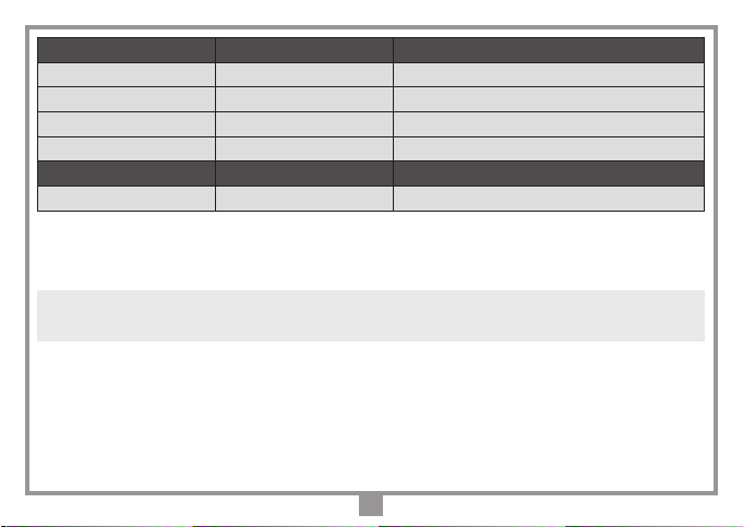
Descrizione
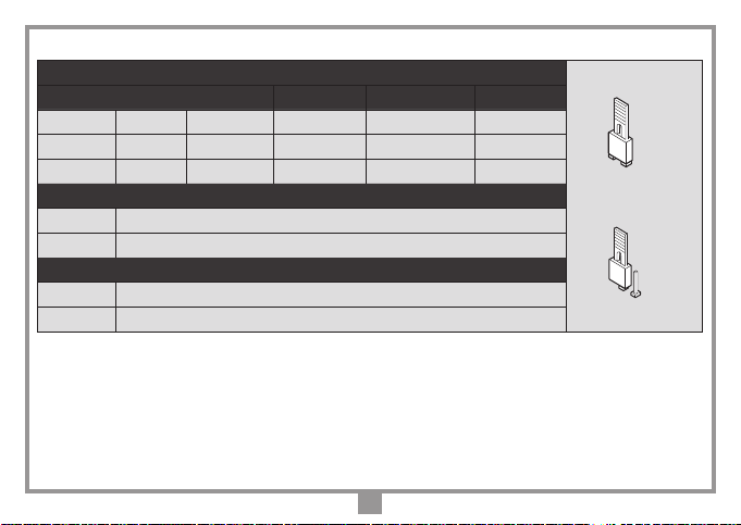
I sistemi di radiocomando S504 e S508 sono composti da uno o più trasmettitori e da uno o più radioprogrammatori
che saranno combinati in relazione alle esigenze speciche d'impianto. Nel radioprogrammatore si possono memo-
rizzare no a 1000 codici diversi; i codici vengono, in fase di memorizzazione, trasferiti in una memoria non volatile.
Importante: Poiché ad ogni comando il codice trasmesso cambia, se la trasmissione viene interrotta da un
disturbo, il ricevitore si aspetta un codice diverso, pertanto per ristabilire il comando è necessario rilasciare e
ripremere il tasto del trasmettitore.
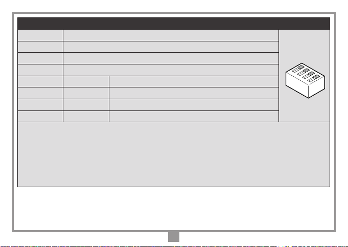
Possibilità d'impiego
Il radioprogrammatore permette il comando a distanza di un motore monofase 230 Vac 400 W e trova il suo miglior
utilizzo nel comando di tende e tapparelle automatizzate. L’apparecchiatura è predisposta per il collegamento
dell’anemometro.

3
Modulo di memoria ZGB24LC64-I/P
Costituita da una memoria non volatile di tipo EEPROM, contiene i codici dei trasmettitori e permette la
memorizzazione di 1000 codici. Nel modulo i codici vengono mantenuti anche in assenza di alimentazione.
Attenzione! La rimozione e l’inserimento del modulo di memoria deve essere eseguito a
radioprogrammatore spento, pena la corruzione dei dati in essa contenuti.
PREDISPOSIZIONE IMPIANTO
Per ottenere la portata massima del sistema radiocomando è bene scegliere con attenzione il punto
d'installazione dell’antenna. La portata è strettamente legata alle caratteristiche tecniche del sistema e
varia in base alle caratteristiche del luogo di postazione. Per portata si intende la distanza tra segnale
trasmesso e/o ricevuto a buon ne. È consigliato l'utilizzo dell'antenna Cardin ANS400/ANQ800-1 per
ottenere un funzionamento ottimale dell'impianto. Collegare al ricevitore l'antenna accordata con un
cavo coassiale RG58 (impedenza 50Ω) lungo max. 15 m.
Trasmettitori 433 MHz Trasmettitori 868 MHz Descrizione
TXQ504C2 TXQ508C2 Trasmettitore precodicato 2 funzioni
TXQ504C4 TXQ508C4 Trasmettitore precodicato 4 funzioni
TXQPRO504-4 TXQPRO508-4 Trasmettitore industriale precodicato 4 funzioni
TXQPRO504-4A TXQPRO508-4A Trasmettitore industriale precodicato 4 funzioni + antenna
Radioprogrammatore433MHz Radioprogrammatore 868 MHz Descrizione
RPQ504RNA0 RPQ508RNA0 Radioprogrammatore per tapparelle automatizzate

4
Trasmettitore
Il trasmettitore è precodificato e utilizza un circuito integrato programmato in fabbrica con un numero
identicativo unico per ogni trasmettitore; tutti i parametri necessari alla codica sono contenuti in questo
circuito integrato. Il trasmettitore possiede un meccanismo di auto-spegnimento dopo almeno 20 secondi
di attivazione continuata (per limitare il consumo della batteria).
Funzione di blocco tasti
• Il trasmettitore ha la possibilità di inserire la funzione di blocco tasti, modalità
che protegge l’apparecchio da attivazioni casuali (involontarie):
- per attivare la funzione tenere premuto “MR” per 8 secondi nché lampeggia
il led arancione; a questo punto per attuare un comando sarà necessario
premere tre volte consecutive il tasto voluto;
- per ripristinare la funzione standard tenere premuto “MR” per 8 secondi nché
il led arancione lampeggia.
Installazione
In base alla tipologia e alle caratteristiche d’impianto individuare il punto di posa dell’apparecchiatura.
L’apparecchiatura dovrà essere collocata:
- in ambiente interno; al riparo da urti e manomissioni ed in una posizione facilmente raggiungibile dal
tecnico, per interventi di manutenzione.
• Svitare le due viti di ssaggio e alzare il coperchio.
• Tracciare (con l’ausilio della scatola) i due punti di ssaggio e ssare il contenitore utilizzando due viti
autolettanti M4 e relativi tasselli.
• Togliere le due protezioni in plastica sull’ingresso dei cavi.
1
2
MR

5
Collegamento elettrico (fig. 1-2)
Prima di eseguire il collegamento elettrico accertarsi che:
- la tensione e la frequenza riportate sulla targhetta caratteristiche corrispondano a quelle dell’impianto di
alimentazione;
- un interruttore bipolare con apertura tra i contatti di almeno 3 mm sia inserito a monte dell’apparecchiatura;
- i cavi della linea 230V passino attraverso i fori "A", separati dai cavi di collegamento in bassa tensione che
passano attraverso i fori "B";
- i cavi di collegamento siano protetti da sollecitazioni meccaniche;
Attenzione: ai morsetti (1…6) per circuiti esterni devono essere collegati solo circuiti a bassissima tensione
di sicurezza.
1 Massa antenna ricevitore radio
2Centrale antenna con lo rigido da 17 cm in dotazione
(nel caso si utilizzi un'antenna esterna collegarla con cavo coassiale RG58 imp. 50Ω)
3 Ingresso anemometro
4 Comune per tutti gli ingressi di comando
5 Ingresso tasto di chiusura (N.A.)
6 Ingresso tasto di apertura (N.A.)
7 Uscita motore (chiusura)
8 Uscita motore (apertura)
9 Uscita motore (comune)
10-11 Alimentazione 230Vac 50-60Hz
12 Ingresso terra alimentazione
13 Uscita terra motore
2 3 4 5 6
DC0565
CS1488
1
F3.15A
ANEM
8 9 10 11
7
13
12
TA M
CH.
COM
A P.
c
230V~
4
3
21
ON
D1
P1
TC LN
B1
RF MODULE
CODES
M1
J1 J2 J3 J4
Pos.1 Pos.2 J1
J2
J3
J4
J5
B B A
COLLEGAMENTO RADIO RENO
Radio Reno S504
01-06-2016
DC0565 Description:
Product Code :
Date :
Drawing number :
P.J.Heath
CARDIN ELETTRONICA S.p.A - 31020 San Vendemiano (TV) Italy - via Raffaello, 36 Tel: 0438/401818 Fax: 0438/401831
Draft :
All rights reserved. Unauthorised copying or use of the information contained in this document is punishable by law
L1
L2
1

6
Scheda elettronica
B1 Buzzer per segnalazione sonora
D1 Dip-switch per selezione velocità vento
F1 Fusibile 3.15A ritardato
J1 Jumper abbinamento CH radio
J2 Jumper abbinamento CH radio
J3 Jumper abilitazione buzzer
J4 Jumper blocco comandi per
intervento anemometro
J5 Jumper memorizzazione rapida
L1 LED alimentazione
L2 LED di segnalazione gestione
codici dei trasmettitori *
M1
Modulo di memoria
P1
Pulsante di programmazione codici
*
Se il led "L2" lampeggia a gruppi di cinque continuamente signica che la memoria è mancante
o guasta. Se invece, il led "L2" lampeggia continuamente è necessario premere il tasto "P1" per
5 secondi no allo spegnimento del led (formattando la memoria per la serie S500).
2 3 4 5 6
DC0565
CS1488
1
F3.15A
ANEM
8 9 10 11
7
13
12
TA M
CH.
COM
A P.
c
230V~
4
3
21
ON
D1
P1
TC LN
B1
RF MODULE
CODES
M1
J1 J2 J3 J4
Pos.1 Pos.2 J1
J2
J3
J4
J5
B B A
COLLEGAMENTO RADIO RENO
Radio Reno S504
01-06-2016
DC0565 Description:
Product Code :
Date :
Drawing number :
P.J.Heath
CARDIN ELETTRONICA S.p.A - 31020 San Vendemiano (TV) Italy - via Raffaello, 36 Tel: 0438/401818 Fax: 0438/401831
Draft :
All rights reserved. Unauthorised copying or use of the information contained in this document is punishable by law
L1
L2
2

7
OPERAZIONI DI GESTIONE IMPIANTO
Attenzione! Prima di procedere alla prima memorizzazione dei trasmettitori, ricordarsi di cancellare
interamente la memoria
• Memorizzazione di un codice canale
1. Premere e tenere premuto il tasto "P1": il LED "L2" lampeggia lentamente.
2. Attivare contemporaneamente il trasmettitore sul canale da memorizzare, "L2" rimane acceso per 2
secondi segnalando che il canale è stato memorizzato; se il LED continua a lampeggiare lentamente, allora
il canale è già stato memorizzato precedentemente. È possibile memorizzare un solo canale alla volta. Per
inserire un canale successivo ripetere i punti 1 e 2 dopo aver rilasciato il tasto. Quando la memoria codici
è completa (1000 trasmettitori memorizzati) è possibile memorizzare un nuovo trasmettitore solamente
dopo averne cancellato completamente uno esistente o tramite la cancellazione completa della memoria.
• Cancellazione di un codice canale (tramite un trasmettitore associato)
1. Premere due volte il tasto "P1"; alla seconda pressione tenere premuto il tasto: il LED "L2" lampeggia a
brevi impulsi.
2. Attivare il trasmettitore sul canale da cancellare no a quando il LED "L2" rimane acceso per 2 secondi
segnalando che il canale è stato cancellato.
Ripetere i punti 1 e 2 per cancellare ulteriori canali, dopo aver rilasciato il tasto.
• Cancellazione completa memoria codici (utenti)
- Premere per 3 volte "P1"; alla terza pressione tenere premuto il tasto. Durante la procedura di
cancellazione (3-4 secondi) il LED "L2" rimane acceso. A ne cancellazione il LED lampeggia 3 volte; a
questo punto rilasciare il tasto.

8
MEMORIZZAZIONE CODICE TX-TX
TRQ504
29-10-2013
DM0910 Description :
Product Code :
Date :
Drawing number :
P.J.Heath
CARDIN ELETTRONICA S.p.A - 31020 San Vendemiano (TV) Italy - via Raffaello, 36 Tel: 0438/401818 Fax: 0438/401831
Draft :
All rights reserved. Unauthorised copying or use of the information contained in this document is punishable by law
MR
A
MR
B
1
2
3
MEMORIZZAZIONE CODICE TX-TX
TXQ504C4
29-10-2013
DM0911 Description :
Product Code :
Date :
Drawing number :
P.J.Heath
CARDIN ELETTRONICA S.p.A - 31020 San Vendemiano (TV) Italy - via Raffaello, 36 Tel: 0438/401818 Fax: 0438/401831
Draft :
All rights reserved. Unauthorised copying or use of the information contained in this document is punishable by law
A
MEMORIZZAZIONE CODICE TX-TX
TXQ504C4
29-10-2013
DM0912 Description :
Product Code :
Date :
Drawing number :
P.J.Heath
CARDIN ELETTRONICA S.p.A - 31020 San Vendemiano (TV) Italy - via Raffaello, 36 Tel: 0438/401818 Fax: 0438/401831
Draft :
All rights reserved. Unauthorised copying or use of the information contained in this document is punishable by law
B
• Memorizzazione rapida
Questa procedura consiste nell'abilitazione di un nuovo trasmettitore da postazione remota mediante l'ausilio di un
altro trasmettitore già memorizzato nell'impianto. Non essendo richiesta la presenza di ricevitori questa procedura può
avvenire in qualsiasi luogo lontano dall'impianto (per esempio nel vostro punto vendita di ducia).
L'abilitazione alla procedura di "memorizzazione rapida" viene abilitata o disabilitata sul ricevitore tramite
l’inserimento/disinserimento del jumper R.MEMO:
• Jumper R.MEMO inserito: memorizzazione rapida abilitata
• Jumper R.MEMO disinserito: memorizzazione rapida disabilitata.
- Togliere il guscio superiore dei trasmettitori da memorizzare e di quello già memorizzato facendo leva come indicato in
gura (dett. a).
- Afancare il trasmettitore A, già memorizzato sul ricevitore, al trasmettitore nuovo B(dett. b).
- Con un adeguato oggetto appuntito premere e rilasciare il tasto MR sui due trasmettitori (in sequenza o simultaneamente).
- I led arancione dei due trasmettitori lampeggiano lentamente.
- Premere e rilasciare sul trasmettitore Aun tasto di canale già attivo sul ricevitore (dett. c).
- Il led del nuovo trasmettitore Brimane acceso per 3 secondi per confermare la memorizzazione (dett. d).
Il trasmettitore Bè abilitato al comando del ricevitore esattamente come il trasmettitore A.
3

9
Dip di selezione funzionamento anemometro
Dip 1 - OFF Abilita la chiusura forzata all’accensione del radioprogrammatore
Dip 1 - ON Disabilita la chiusura forzata all’accensione del radioprogrammatore
Dip 2 - OFF Abilita la funzione anemometro
Dip 2 - On Disabilita la funzione anemometro
Dip 3 - OFF Dip 4 - OFF Velocità vento 20 km/ora
Dip 3 - OFF Dip 4 - ON Velocità vento 35 km/ora
Dip 3 - ON Dip 4 - OFF Velocità vento 42 km/ora
Dip 3 - ON Dip 4 - ON Velocità vento 50 km/ora
Con l’anemometro installato si può programmare la chiusura automatica in condizioni di vento forte.
Il dip-switch "D1" (g. 2) ha quattro livelli di selezione: 20-35-42 e 50 km/ora. Con anemometro attivo
(situazione di vento e jumper J4 inserito) è inibita la funzione di radiocomando o comandi via lo per
10 minuti. Per effettuare la regolazione della sensibilità durante la fase d’installazione è possibile
annullare tale periodo di blocco togliendo e rimettendo l’alimentazione: in tal caso converrà disinserire
momentaneamente la richiusura forzata (Dip 1 "ON").
1234
ON

10
Impostazione jumper di selezione
Jumper associazione canale / funzione
J1 J2 CHA CHB CHC CHD
POS. 1 POS. 1 APRE CHIUDE BLOCCO
DINAMICO
POS. 2 POS. 1 APRE CHIUDE APRE CHIUDE
POS. 1 POS. 2
DINAMICO DINAMICO DINAMICO DINAMICO
J3 Jumper abilitazione buzzer
POS. 1 Buzzer abilitato
POS. 2 Buzzer escluso
J4 Jumper blocco comandi per intervento anemometro
POS. 1 Funzione attiva
POS. 2 Funzione esclusa
Pos. 2
Pos.1

11
CARATTERISTICHE TECNICHE
RADIOPROGRAMMATORE
- alimentazione ............................................................................................................................... 230 Vac, 50-60Hz
- uscita comando motore .................................................................................................................................400 W
- tempo di lavoro sso...........................................................................................................................................90 s
- velocità vento (selezionabile) ................................................................................................... 20-35-42-50 km/ora
- trasmettitori memorizzabili................................................................................................................................ 1000
- temperatura di esercizio ..................................................................................................................... -20°…+55 °C
TRASMETTITORE
- frequenza di trasmissione........................................................................................................ 433,92 / 868,3 MHz
- potenza apparente irradiata..........................................................................................-10…-7dBm (100-200 µW)
- modulazione................................................................................................................................................ FM/FSK
- alimentazione (batteria litio) .......................................................................................................... 3V (1 x CR2032)
- assorbimento.................................................................................................................................................. 18 mA
- temperatura di esercizio .....................................................................................................................-10°…+55 °C
- umidità relativa ................................................................................................................................................<95%
- tipo di codica........................................................................................................................................rolling code
- numero di combinazioni complessive (128 bit):..................................................................................................2128
- numero delle funzioni (canali) ................................................................................................................................. 4
- autospegnimento: ............................................................................................................dopo almeno 20 secondi
- portata (trasmettitori tascabili) ..............................................................................................................100 - 150 m
- portata (trasmettitori industriali)......................................................................................................................200 m
- portata (trasmettitori industriali con antenna esterna) ...................................................................................700 m

12
REMARKS
These instructions are aimed at professionally qualied "installers of electrical equipment" and must respect the local standards and
regulations in force. The use and installation of these appliances must rigorously respect the indications supplied by the manufacturer
and the safety standards and regulations in force.
Attention! Only for EU customers - WEEE marking. This symbol indicates that once the products life-span
has expired it must be disposed of separately from other rubbish. The user is therefore obliged to either take
the product to a suitable differential collection site for electronic and electrical goods or to send it back to
the manufacturer if the intention is to replace it with a new equivalent version of the same product. Suitable
differential collection, environmental friendly treatment and disposal contributes to avoiding negative effects on the
ambient and consequently health as well as favouring the recycling of materials. Illicitly disposing of this product by the
owner is punishable by law and will be dealt with according to the laws and standards of the individual member nation.
Description
The S504 and S508 Radio control systems consist of one or more transmitters and one or more radio pro-
grammers which can be combined to meet the specic needs of the system. The radio programmer is able to
memorise up to 1000 different codes and the generated code is memorised in a non-volatile memory module.
Important: The transmitted code changes for each command (rolling code). If disturbance interrupts the
transmission, the receiver will wait for a different code, the relay can then only be activated by rst releasing
and then pressing the transmitter channel button again.
Use
The radio programmer allows the remote control of one single phase motor 230 Vac 400 W and nds its
best use in the command of automatic awnings and rolling shutters. The appliance is designed for the
connection of an anemometer.

13
Memory module ZGB24LC64-I/P
The module is furnished with a none-volatile EEPROM type memory and contains the transmitter codes and
allowsyoutomemoriseupto1000 codes.Theprogrammedcodes remainstoredevenintheabsenceofpower.
Attention! Removing and inserting the memory module must be carried out when the receiver is switched
off otherwise the memory content could become corrupt.
PREPARING THE SYSTEM
To obtain the best results from the radio control system the aerial installation site should be carefully chosen.
‘Range’ is intended to mean the working distance, measured in free space, between the receiver and the
transmitter with the aerial installed. The range is therefore closely linked to the technical characteristics of
the system and varies according to the characteristics of the site in which the system is located.
For best performance we advise you to use the Cardin ANS400 / ANQ800-1 aerial. Wire the aerial to the
receiver using a coaxial cable RG58 (impedance 50Ω) with a maximum length of 15 m.
Transmitters 433 MHz Transmitters 868 MHz Description
TXQ504C2 TXQ508C2 2-channel precoded transmitters
TXQ504C4 TXQ508C4 4-channel precoded transmitters
TXQPRO504-4 TXQPRO508-4 4-channel precoded industrial transmitters
TXQPRO504-4A TXQPRO508-4A 4-channel precoded industrial transmitters + aerial
Radioprogrammer433MHz Radio programmer868MHz Description
RPQ504RNA0 RPQ508RNA0 Radio programmer for rolling shutters

14
Transmitters
The transmitter is pre-coded and is tted with an integrated circuit which is programmed in the factory
with a unique identication number. All the code parameters are contained in this integrated circuit. The
transmitter has an automatic shut down mechanism which cuts in after at least 20 seconds of continuous
use (this limits battery consumption).
Key block function
• A key block function has been added to protect the appliance from accidental
activation;
- to activate the function press and hold down “MR” for 8 seconds until the orange
led starts ashing, at this point to activate a command you will need to press the
required key three times consecutively;
- to reset the function to standard operation standard press and hold down “MR”
for 8 seconds until the orange led starts ashing.
Installation
Depending on the type of installation, work out the position in which the programmer will be situated
remembering that the site must be:
- installed indoors; a position safe from accidental collision and tampering and in a position which the
technician can easily reach.
• Remove the two holding screws and lift up the cover
• Using the container as a template mark the four points at which the fastening holes are to be drilled and
fasten down using four self-tapping M4 screws and relative rawplugs.
• Remove the two plastic cable protection covers.
1
2
MR

15
Electrical connection (fig. 1)
Before connecting the device to the mains make sure that:
- the voltage and frequency rated on the data plate conform to those of the mains supply;
- an all pole circuit breaker which leaves at least 3 mm between the contacts has been installed between
the device and the mains;
- the high voltage 230V wires pass through the holes marked "A" and are routed separately from the low
voltage wires which pass through the holes marked "B";
- the wires are fastened down using a cable clamp.
Caution: only low voltage circuits may be wired to the external circuit binding posts 1…6.
1
Outer conductor for radio receiver antenna
2
Inner conductor for radio receiver antenna with a 17 cm piece of rigid wire (if an external antenna is
tted use a coaxial type cable RG58 with an impedance of 50Ω)
3
Anemometer input
4
Common for all inputs
5
Closing button input (N.O.)
6
Opening button input (N.O.)
7
Motor output (closing)
8
Motor output (opening)
9
Motor output (neutral)
10-11 Power supply 230 Vac 50-60 Hz
12
Power supply earth connection
13 Motor output earth connection
2 3 4 5 6
DC0565
CS1488
1
F3.15A
ANEM
8 9 10 11
7
13
12
TA M
CH.
COM
A P.
c
230V~
4
3
21
ON
D1
P1
TC LN
B1
RF MODULE
CODES
M1
J1 J2 J3 J4
Pos.1 Pos.2 J1
J2
J3
J4
J5
B B A
COLLEGAMENTO RADIO RENO
Radio Reno S504
01-06-2016
DC0565 Description:
Product Code :
Date :
Drawing number :
P.J.Heath
CARDIN ELETTRONICA S.p.A - 31020 San Vendemiano (TV) Italy - via Raffaello, 36 Tel: 0438/401818 Fax: 0438/401831
Draft :
All rights reserved. Unauthorised copying or use of the information contained in this document is punishable by law
L1
L2
1

16
Electronic card
B1 Indicator buzzer
D1 Wind speed selection dip-switch
F1 3.15A delayed fuse
J1 Radio channel association Jumper
J2 Radio channel association Jumper
J3 Buzzer enable jumper
J4 Jumper to block commands
after wind speed sensor cuts in
J5 Rapid memorising jumper
L1 Power On LED
L2 Transmitter code management
LED *
M1
Memory module
P1
Programming button
*
If led "L2" ashes continuously in groups of ve the memory module is either missing or damaged. If
instead, led "L2" ashes continuously you will need to press down buttons "P1" for 5 seconds until the
led switches off
(formatting the memory module for the S500 series)
.
2 3 4 5 6
DC0565
CS1488
1
F3.15A
ANEM
8 9 10 11
7
13
12
TA M
CH.
COM
A P.
c
230V~
4
3
21
ON
D1
P1
TC LN
B1
RF MODULE
CODES
M1
J1 J2 J3 J4
Pos.1 Pos.2 J1
J2
J3
J4
J5
B B A
COLLEGAMENTO RADIO RENO
Radio Reno S504
01-06-2016
DC0565 Description:
Product Code :
Date :
Drawing number :
P.J.Heath
CARDIN ELETTRONICA S.p.A - 31020 San Vendemiano (TV) Italy - via Raffaello, 36 Tel: 0438/401818 Fax: 0438/401831
Draft :
All rights reserved. Unauthorised copying or use of the information contained in this document is punishable by law
L1
L2
2

17
SYSTEM MANAGEMENT OPERATIONS
Attention! Before memorising the transmitters for the rst time remember to cancel the entire memory
content.
• Memorizing a channel code
1. Press and hold down button "P1", LED "L2" will ash slowly.
2. At the same activate the transmitter channel to be memorised, "L2" will remain lit for 2 seconds
indicating that the channel has been memorised; if the LED keeps ashing slowly the channel was
already memorised. Only one channel can be memorised at a time. To insert another channel repeat
points 1 and 2 after having released the button. When the code memory is complete (1000 transmitters
memorised) you may only memorise a new transmitter after you have completely cancelled an existing
transmitter or after cancelling the entire memory content.
• Deleting a channel code (via an associated transmitter)
1. Press the button "P1" twice and hold down after pressing the second time: LED "L2" will ash at brief
intervals.
2. Activate the transmitter channel to be cancelled, "L2" will remain lit for 2 seconds indicating that the
channel has been cancelled;.
To cancel another channel repeat points 1 and 2 after having released the button.
• Deleting the entire code memory content (users)
- Press "P1" three and hold down after pressing the third time. During the cancellation procedure (3-4
seconds) LED "L2" remains lit. After cancellation the LED will ash 3 times; at this point release the
button.

18
• Rapid memorising procedure
This procedure allows you to enable a new transmitter (from a remote position) with the help of a transmitter that has
already been memorised in the system. As the presence of the receiver is not required this procedure can be carried out
in any remote location (for example in your chosen sales outlet).
Access to the "rapid memorising" procedure can be enabled or disabled on the receiver by inserting (or
removing) the jumper R.MEMO:
• Jumper R.MEMO inserted: the rapid memorization procedure is enabled.
• Jumper R.MEMO not inserted: the rapid memorization procedure is disabled.
- Remove the upper cover from the transmitter to be memorised and from the transmitter that has already been
memorised as shown in the drawing below (det. a).
- Place the transmitter A, that has already been memorised in the receiver, beside the new transmitter B(det. b).
- Using a pointed object press and release the MR button on both transmitter (in sequence or simultaneously).
- The orange LEDS on the transmitters will ash slowly.
- Press and release a channel button on transmitter Athat is already present in the receiver (det. c).
- The led of the new unit Bwill remain lit for 3 seconds to conrm memorization (det. d).
Transmitter Bwill now command the receiver exactly like transmitter A.
MEMORIZZAZIONE CODICE TX-TX
TRQ504
29-10-2013
DM0910 Description :
Product Code :
Date :
Drawing number :
P.J.Heath
CARDIN ELETTRONICA S.p.A - 31020 San Vendemiano (TV) Italy - via Raffaello, 36 Tel: 0438/401818 Fax: 0438/401831
Draft :
All rights reserved. Unauthorised copying or use of the information contained in this document is punishable by law
MR
A
MR
B
1
2
3
MEMORIZZAZIONE CODICE TX-TX
TXQ504C4
29-10-2013
DM0911 Description :
Product Code :
Date :
Drawing number :
P.J.Heath
CARDIN ELETTRONICA S.p.A - 31020 San Vendemiano (TV) Italy - via Raffaello, 36 Tel: 0438/401818 Fax: 0438/401831
Draft :
All rights reserved. Unauthorised copying or use of the information contained in this document is punishable by law
A
MEMORIZZAZIONE CODICE TX-TX
TXQ504C4
29-10-2013
DM0912 Description :
Product Code :
Date :
Drawing number :
P.J.Heath
CARDIN ELETTRONICA S.p.A - 31020 San Vendemiano (TV) Italy - via Raffaello, 36 Tel: 0438/401818 Fax: 0438/401831
Draft :
All rights reserved. Unauthorised copying or use of the information contained in this document is punishable by law
B
3

19
Dip-switch settings for the windspeed sensor
Dip 1 - OFF Enable forced closing on Power ON
Dip 1 - ON Disable forced closing on Power ON
Dip 2 - OFF Enable the wind speed function
Dip 2 - On Disable the wind speed function
Dip 3 - OFF Dip 4 - OFF Wind speed 20 km/hour
Dip 3 - OFF Dip 4 - ON Wind speed 35 km/hour
Dip 3 - ON Dip 4 - OFF Wind speed 42 km/hour
Dip 3 - ON Dip 4 - ON Wind speed 50 km/hour
With a windspeed sensor installed you may program automatic closing in strong wind conditions.
The dip-switch "D1" (g. 2) has four settings: 20-35-42 and 50 km/hour. When the anemometer is
active (strong wind conditions with jumper J4 inserted) control via the transmitter or via cable will
be excluded for 10 minutes. To calibrate the sensitivity level during installation you can override this
block by switching the power off and on again: however in this case you are advised to temporarily
deactivate automatic reclosing (Dip 1 "ON").
1234
ON

20
Selection jumpers
Radio channel / function association Jumper
J1 J2 CHA CHB CHC CHD
POS. 1 POS. 1 OPEN CLOSE BLOCK
SEQUENTIAL
POS. 2 POS. 1 OPEN CLOSE OPEN CLOSE
POS. 1 POS. 2
SEQUENTIAL SEQUENTIAL SEQUENTIAL SEQUENTIAL
J3 Buzzer enable jumper
POS. 1 Buzzer enabled
POS. 2 Buzzer disabled
J4 Jumper to block commands after wind speed sensor cuts in
POS. 1 Function active
POS. 2 Function excluded
Pos. 2
Pos.1
This manual suits for next models
3
Table of contents
Languages:
Other Cardin Motherboard manuals