Cardin S449 User manual

ZVL413.01 S449
11-06-2001
RP449RN
CARDIN ELETTRONICA spa
Via Raffaello, 36- 31020 San Vendemiano (TV) Italy
Tel: +39/0438.404011-401818
Fax: +39/0438.401831
Http: www.cardin.it
ZVL413.01 MOD: 06-04-2004
Se il codice non viene memorizzato:
- Il codice trasmesso esiste già in memoria.
- La memoria è completa (con 20 trasmettitori già memorizzati). In questo caso è possibile inserire
un nuovo codice solo cancellando un codice esistente o tramite la cancellazione della memoria
intera (vedi procedura di cancellazione).
Attenzione: quando la memoria è completamente occupata, il buzzer emette una segnalazione
sonora per circa 5 secondi.
Procedura di cancellazione di un codice nel ricevitore:
1) Premere due volte il pulsante "P1" (fig.5) e tenerlo premuto. Il ricevitore emetterà una serie di "bip"
di breve durata.
2) Trasmettere il canale da cancellare (per almeno 5 secondi). Il ricevitore emetterà una serie di "bip"
ad intervalli più brevi indicando che il canale è stato cancellato. Per cancellare un successivo codice
ripetere i punti 1 e 2.
Memorizzazione di ulteriori canali via radio (fig.4b)
La memorizzazione può essere attivata via radio (senza aprire la scatola dove è alloggiato il
ricevitore) solamente se il jumper "J1" è inserito (fig.5).
Attenzione! Ogni cambiamento nell'impostazione del jumper per essere effettiva richiede di
togliere e ridare l'alimentazione al ricevitore.
1) Assicurarsi che il jumper "J1" sia inserito sul ricevitore
2) Utilizzando un radiocomando, in cui almeno uno dei tasti di canale "A-B-C-D" sia già stato memo-
rizzato nel ricevitore, attivare il tasto "MR" come indicato in figura "4b".
Nota: Tutti i ricevitori raggiungibili dall'emissione del radiocomando, e che abbiano almeno un canale
del trasmettitore memorizzato, attiveranno contemporaneamente il buzzer di segnalazione.
3) Attivare uno dei tasti di canale del trasmettitore. I ricevitori che non contengono il codice di tale
tasto si disattiveranno, con l'emissione di un "bip" lungo 5 secondi; quello invece che contiene
il codice emetterà un altro "bip" che dura un secondo, entrando effettivamente nella modalità di
memorizzazione "via radio".
4) Premere un tasto di canale sul trasmettitore da memorizzare; ad avvenuta memorizzazione il
ricevitore emetterà 2 "bip" di mezzo secondo, dopodiché il ricevitore sarà pronto a memorizzare
un altro codice.
5) Per uscire dalla modalità lasciare trascorrere 3 secondi senza memorizzare codici. Il ricevitore
emetterà un "bip" lungo 5 secondi ed uscirà dalla modalità.
ATTENZIONE: Il radioprogrammatore è in grado di memorizzare le funzioni di 20 trasmettitori differenti,
per un massimo quindi di 80 tasti di canale; quando si memorizza "via radio" un codice di canale, si
presentano dunque le tre possibilità seguenti:
• Sono stati memorizzati meno di 20 trasmettitori: la procedura prosegue come descritto sopra.
• Sono già stati memorizzati 20 trasmettitori, ma non sono stati memorizzati tutti i canali per ognuno di
essi:saràpossibilealloraaggiungereinmemoriaunoopiùcanalisolamentediquestitrasmettitori(non
è possibile memorizzare un canale di un ventunesimo trasmettitore). La segnalazione sonora, dopo
aver premuto il tasto "MR", sarà la seguente: sequenza rapida di "bip" (che segnala l’impossibilità
di memorizzare un nuovo TX) seguita da un "bip" di durata 1 secondo (che segnala la possibilità di
procedere alla memorizzazione via radio.
• Sono stati memorizzati tutti i canali per 20 trasmettitori: la memoria è completamente occupata, per
cui quando si preme il tasto "MR" il radioprogrammatore farà solamente la sequenza di "bip" rapidi
ed uscirà dalla modalità di programmazione codici.
ANEMOMETRO
Con l’anemometro installato si può programmare la chiusura automatica in condizioni di vento forte.
Il dip-switch "D1" (fig.5) ha quattro livelli di selezione: 20-35-42 e 50 km/ora. Con anemometro
attivo (situazione di vento) è inibita la funzione di radiocomando o comandi via filo per 10 minuti.
Per effettuare la regolazione della sensibilità durante la fase d’installazione è possibile annullare
tale periodo di blocco togliendo e rimettendo l’alimentazione: in tal caso converrà disinserire
momentaneamente la richiusura forzata (Dip 1 "ON" fig.5).
Selezioni Dip-switch D1
Richiusura forzata
Selezionando Dip 1 su "OFF" si abilita tale funzione, che consiste nella chiusura forzata ad ogni
riavvio del radioprogrammatore.
Dip 1 ON Disabilita la chiusura forzata all’accensione
Dip 2 ON Esclude la funzione anemometro
Dip 3 OFF
Dip 4 OFF
Dip 3 OFF
Dip 4 ON
Dip 3 ON
Dip 4 OFF
Dip 3 ON
Dip 4 ON
CARATTERISTICHE TECNICHE
Ricevitore
- alimentazione ..........................................................................................................230V ac, 50-60 Hz
- canali memorizzabili..........................................................................................................................80
- velocità vento (selezionabile) ...............................................................................20-35-42-50 km/ora
- temperatura di esercizio...................................................................................................-20°…+60°C
- fusibile................................................................................................................... F 3.15A 250V (5x20)
Trasmettitore
- frequenza di trasmissione................................................................................................. 433.92 MHz
- tolleranza sulla frequenza di trasmissione...............................................................................±30 kHz
- potenza apparente irradiata...................................................................... -10…-7dBm (100-200 µW)
- emissione dei prodotti armonici...............................................................................<-54dBm (<4 nW)
- modulazione.............................................................................................................................FM/FSK
- modulazione con ∆F ................................................................................................................≤20 kHz
- alimentazione (batteria litio) ...............................................................................................2 x CR2032
- assorbimento...............................................................................................................................35 mA
- temperatura di esercizio..................................................................................................-10°…+55 °C
- umidità relativa ............................................................................................................................<95%
- tipo di codifica....................................................................................................................rolling code
- numero di combinazioni complessive (66 bit):.................................................................................2
66
- numero delle funzioni (canali).............................................................................................................. 4
- autospegnimento (minimo): ...................................................................................... dopo 25 secondi
Descrizione
Il sistema di radiocomando S449 in "FM" è composto da uno o più trasmettitori e da uno o più ricevitori
che saranno combinati in relazione alle esigenze specifiche d'impianto. La serie S449 usa un sistema di
codifica ad alta affidabilità garantita dall'uso di codici dinamici. Ad ogni trasmissione il codice cambia
in base ad un algoritmo che solo il ricevitore è in grado di riconoscere, stabilendo se la trasmissione è
corretta rispetto al codice originale. Il codice viene memorizzato via radio sul ricevitore. Nel ricevitore
si possono memorizzare fino a 20 trasmettitori diversi per un totale di 80 tasti di canale (max.) che
vengono mantenuti in memoria anche in assenza di corrente.
Importante: Poiché ad ogni comando il codice trasmesso cambia, se la trasmissione viene interrotta
da un disturbo, il ricevitore si aspetta un codice diverso, pertanto per ristabilire il comando è necessario
rilasciare e ripremere il tasto del trasmettitore.
Possibilità d'impiego
Il radioprogrammatore permette il comando a distanza di un motore monofase 230V ac, 50-60Hz,
400W e trova il suo miglior utilizzo nel comando di tapparelle automatiche. Il radioprogrammatore
dispone di due ingressi a morsettiera per comandi indipendenti di apertura e chiusura, secondo due
possibili modalità:
1) Tenendo premuto il pulsante "TA" o "TC" per un tempo superiore a 1 secondo, il motore verrà
comandato "a uomo presente"; il blocco si otterrà al rilascio del pulsante.
2) Premendo per un breve tempo (meno di un secondo) il pulsante "TA" o "TC", il motore verrà coman-
dato "in automatico" e si arresterà alla fine della manovra (tempo massimo di lavoro: 1.5 minuti circa,
non regolabile). Per bloccare il motore, premere contemporaneamente entrambi i pulsanti.
Perl’azionamentoincomunedipiùmotorisipotràutilizzareilradiocomandoavendocuradimemorizzare
gli stessi canali su più radioprogrammatori. Le funzioni dei tasti del radiocomando sono prefissate,
come indicato in figura 3.
Versioni trasmettitori
TRQ449400 Trasmettitori tascabili 4 tasti
TRQ44940M Pulsantiera radio per fissaggio a muro 4 tasti
Versioni ricevitori
RP449RNA0 Radioprogrammatore RP449 con anemometro
Installazione ricevitore-antenna
Portata minima e massima dei radiocomandi:
Per portata si intende la distanza utile di funzionamento fra trasmettitore e ricevitore con antenna instal-
lata, e misurata in spazio libero. La portata è quindi strettamente legata alle caratteristiche tecniche del
sistema (potenza e sensibilità) e varia in base alle caratteristiche del luogo di postazione. Per ottenere
il funzionamento ottimale del radiocomando è bene scegliere con attenzione i punti d'installazione del
ricevitore e dell'antenna. È buona norma posizionare il ricevitore a debita distanza da reti di sistemi
computerizzati, da impianti d'allarme e da altre fonti di possibile disturbo.
(Sistemazioni anomale potrebbero comprometterne in parte il funzionamento)
Antenna
L'installazione dell'antenna è fondamentale; collegata al ricevitore rappresenta il punto di ricezione
del radiocomando.
Nella sua installazione si rispettino le seguenti indicazioni.
Il ricevitore è dotato di antenna propria, consistente in uno spezzone di filo rigido, lungo 170mm.
In alternativa è possibile collegare l’antenna accordata ANS400 da collegare al ricevitore mediante
cavetto coassiale RG58 (imp. 50Ω) di lunghezza max. 15m. In tal caso per ottenere il funzionamento
ottimale del radiocomando è bene scegliere con attenzione i punti d’installazione.
Trasmettitore
Il trasmettitore è precodificato e utilizza un circuito integrato programmato in fabbrica con un
numero identificativo unico per ogni trasmettitore; tutti i parametri necessari alla codifica sono
contenuti in questo circuito integrato (non si utilizza una memoria esterna): questo rende molto più
affidabile il meccanismo di gestione della codifica, e più sicuro il sistema. Il trasmettitore possiede un
meccanismo di auto-spegnimento dopo almeno 25 secondi di attivazione continuata (per limitare il
consumo della batteria).
• Questo tempo può variare significativamente da un trasmettitore ad un altro.
Ricevitori
In base alla tipologia e alle caratteristiche d’impianto individuare il punto di posa dell’apparecchiatura.
L’apparecchiatura dovrà essere collocata:
- in ambiente interno;
- al riparo da urti e manomissioni;
- in una posizione facilmente raggiungibile dal tecnico, per interventi di manutenzione.
• Svitare le due viti di fissaggio e alzare il coperchio.
• Tracciare (con l’ausilio della scatola) i due punti di fissaggio e fissare il contenitore utilizzando due
viti autofilettanti M4 e relativi tasselli.
• Togliere le due protezioni in plastica sull’ingresso dei cavi.
Collegamento elettrico
• Prima di eseguire il collegamento elettrico accertarsi che:
- latensioneelafrequenzariportatesullatarghettacaratteristichecorrispondanoaquelledell’impianto
di alimentazione;
- un interruttore onnipolare con apertura tra i contatti di almeno 3mm. sia inserito a monte dell’ap-
parecchiatura;
- i cavi di collegamento siano protetti da sollecitazioni meccaniche.
Gestione codici nel ricevitore (fig.5)
Attenzione!Primadiprocedere allaprimamemorizzazionedeitrasmettitori,ricordarsidicancellare
interamente la memoria.
Verificare che il jumper "J1" sia inserito (solo così il ricevitore potrà dare le segnalazioni acustiche
durante la memorizzazione/cancellazione dei codici.
Per cancellare tutti i codici:
1) Premere tre volte il pulsante "P1" (fig.5) e tenerlo premuto (per almeno 5 secondi). Il ricevitore emette
inizialmente un "bip" continuato, ed a cancellazione avvenuta emette una sequenza rapida di "bip".
Rilasciare il pulsante.
Memorizzazione di un codice nel ricevitore
1) Premere il pulsante "P1" (fig.5) e tenerlo premuto: il ricevitore emetterà una serie di "bip" ad intervalli
regolari.
2) Trasmettere il canale da memorizzare (fig.3, 4).
3) Il ricevitore emetterà una serie di "bip" ad intervalli più brevi indicando che il canale è stato memo-
rizzato. Rilasciare il pulsante "P1". È possibile inserire un solo codice alla volta, per inserire un
successivo codice rilasciare il pulsante e ripetere i punti 1,2,3.
RADIOPROGRAMMATORE A CODICI DINAMICI PER TAPPARELLE
MODELLO DATACODICE SERIE
La serie S449 è conforme ai requisiti essenziali fissati dalla direttiva 99/05/
CE e ad esso sono state applicate le norme tecniche di riferimento.
Frequenza: 433.92MHz per tutti i paesi
}
}
}
}
Velocità vento 20 km/ora
Velocità vento 35 km/ora
Velocità vento 42 km/ora
Velocità vento 50 km/ora
1234
ON

ZVL413.01 S449
11-06-2001
RP449RN
CARDIN ELETTRONICA spa
Via Raffaello, 36- 31020 San Vendemiano (TV) Italy
Tel: +39/0438.404011-401818
Fax: +39/0438.401831
Http: www.cardin.it
If the code is not memorised:
- The code may already exist in memory;
- You have not generated a channel code in the transmitter.
- The memory is full (20 codes already memorised). If this is the case you can only insert a new code
after you have first cancelled an existing one or after wiping the entire memory (see memory cancelling
procedure).
Attention: when the memory is full the buzzer will sound for about 5 seconds. This also happens
each time the receiver is reset.
Cancelling a code in the receiver
1) Press the button "P1" twice (fig.5) and keep it pressed down. The receiver will emit a series of "Beeps"
intermittently.
2) Transmit the channel which is to be memorised (for at least 5 seconds). The receiver will emit a series
of "Beeps" at shorter intervals indicating that the channel has been cancelled. To cancel successive
codes repeat steps 1 and 2.
Memorising a channel ulterior channels via radio (fig.4b)
Memorisation can be activated by radio (without opening the receiver container) only if jumper
"J1" has been inserted (fig.5).
Attention! each time the position of the jumper is changed the receiver must be switched off
and then on again.
1) Make sure that the jumper "J1" has been inserted in receiver.
2) Using a transmitter, in which at least one channel button "A,B,C or D" has already been memorised
in the receiver, press the button "MR" as shown in figure "4b".
Note: all the receivers within range when the channel button is pressed (and which have at least one
of the transmitter channel buttons memorised) will activate their signal buzzer.
3) Press one of the channel buttons on the transmitter. The receivers which do not contain that channel
code will sound a five-second long "Beep" and will then disactivate. The receivers which contain the
channel code will sound a one-second long "Beep" and will enter the remotye programming mode.
4) Pressoneof thechannelbuttonson thetransmitterwhichyouwishto memorise;thereceiverwillsound
2 "Beeps" of half a second each after which the receiver will be ready to receive another code.
5) To leave the programming mode wait for 5 seconds without pressing any buttons. The receiver will
sound a five-second long "Beep" and will then exit the programming mode.
ATTENTION! The radioprogrammer is able to memorise the functions of 20 different transmitters for a
maximum total of 80 channels buttons. When you memorise "via radio" the following possibilities are
thereforte possible:
• Less than 20 transmitters have been memorised therefore proceed as described above.
• 20 transmitters have already been memorised but all the channels for each transmitter have not been
memorised; you may therefore memorise one or more channels from these transmitters ( you cannot
memorise a channel in a twenty-first transmitter). After having pressed the "MR" button there will
be a series or rapid "Beeps" (telling you that you cannot memorise a new transmitter) followed by a
one-second "Beep" (telling you that you can add a new channel via radio).
• All the channels in 20 transmitters have already been memorised and memory is completely full. When
you press the "MR" button the radioprogrammer will emit a sequence of rapid "Beeps" and will exit
the code programming mode.
WINDSPEED SENSOR
With awindspeedsensorinstalledyoumayprogrammingautomaticclosinginstrongwind conditions.
The dip-switch "D1" (fig.5) has four settings: 20-35-42 and 50 km/hour. When the anemometer
is active (strong wind conditions) control via the transmitter or via cable will be excluded for 10
minutes. To calibrate the sensitivity level during installation you can override this block by switch-
ing the power off and on again: however in this case you are advised to temporarily deactivate
automatic reclosing (Dip 1 "ON" fig.5).
Dip-switch D1 settings
Forced closing
In the version with an anemometer the forced closing function can be enabled by moving dip 1 to
the "OFF" position. This will allow forced reclosing each time the radioprogrammer is reset.
Dip 1 ON Exclude forced closing on power on
Dip 2 ON Exclude the anemometer function
Dip 3 OFF
Dip 4 OFF
Dip 3 OFF
Dip 4 ON
Dip 3 ON
Dip 4 OFF
Dip 3 ON
Dip 4 ON
TECHNICAL SPECIFICATIONS
Receiver
- power supply................................................................................................................230V ac, 50-60Hz
- number of channels stored in memory.................................................................................................80
- wind speed settings .................................................................................................... 20-35-42-50 km/h
- operating temperature..........................................................................................................-20°…+60°C
- fuse ........................................................................................................................... F 3.15A 250V (5x20)
Transmitters
- carrier frequency ............................................................................................................................433.92MHz
- carrier frequency tolerance..................................................................................................................±30kHz
- apparent radiated power........................................................................................-10…-7dBm (100-200µW)
- apparent power harmonic products .................................................................................... <-54dBm (<4nW)
- modulation...........................................................................................................................................FM/FSK
- modulated with ∆F .............................................................................................................................≤20 kHz
- power supply (lithium battery)....................................................................................................... 2 x CR2032
- power consumption ................................................................................................................................35mA
- operating temperature range........................................................................................................-10…+55°C
- relative humidity ..................................................................................................................................... <95%
- type of encoding ........................................................................................................................... rolling code
- total number of possible code combinations (66 bit) .................................................................................266
- number of channels .......................................................................................................................................4
- automatic shut down ............................................................................................................after 25 seconds
Description
The S449 Radio control system in "FM" consists of one or more transmitters and one or more receivers which
can be combined to meet the specific needs of the system.
The S449 system uses a highly reliable encoding system guaranteed by the use of dynamic codes. The code
is changed for each encoding transmission through the use of an encoding algorithm which only the receiver
is able to recognise and therefore decide whether or not the code transmitted corresponds to the original
code. The generated code is memorised in the receiver via radio. The receiver is able to memorise up to
20 different transmitters for a maximum total of 80 channels buttons which are maintained in memory even
during blackouts.
Important: The transmitted code changes for each command (rolling code). If disturbance interrupts the
transmission, the receiver will wait for a different code, the relay can then only be activated by first releasing
and then pressing the transmitter channel button again.
Use
The radioprogrammer allows the remote control of a 230V ac, 50-60 Hz, 400W single phase motor and is best
used for the control of automatic rolling shutters. The programmer has two terminal board inputs for independent
opening and closing commands with two function modes:
1) Keeping the "TA" or "TC" buttons pressed for more than one second will force manual control of the the
motor. Releasing the button will block the command.
2) Pressing the "TA" or "TC" buttons for a period less than one second will envoke the automatic command. The
motor will stop after the work cycle time has elapsed (maximum non adjustable time of about 1,5 minutes).
To block the motor press both buttons simultaneously.
To activate more than one motor simultaneously memorise the same channels on different receivers. The button
functions are preset as indicated in figure 3.
Transmitter versions
TRQ449400 Miniaturised transmitters 4 Buttons
TRQ44940M Wall mounted transmitter 4 Buttons
Receiver versions
RP449RNA0 RP449 Radio programmer with a windspeed sensor
Receiver antenna installation
Minimum and maximum range of the radio controls. ‘Range’ is intended to mean the working distance, meas-
ured in free space, between the receiver and the transmitter with the antenna installed. The range is therefore
closely linked to the technical characteristics of the system (power and sensibility) and varies according to the
characteristics of the site in which the system is located. It therefore follows that to obtain the best results from
the radio control the receiver and antenna installation sites should be carefully chosen.
It is good practise to position the receiver away from computer systems, alarm systems and other possible
sources of disturbance.
(A bad choice of positioning could compromise the performance of the receiver).
Antenna
The installation of the antenna is fundamental, connected to the receiver it represents the reception point for
the radio control. When installing the antenna the following points should be observed.
A tuned antenna using a coaxial cable RG58 (impedance 50Ω) with a maximum length of 170mm. must be
installed. The antenna should be positioned out of doors in the highest possible point, visible and away from
metal structures.
Transmitters
The transmitter is pre-coded and is fitted with an integrated circuit which is programmed in the factory
with a unique identification number. All the code parameters are contained in this integrated circuit (external
memory modules are not required) thus making code management more reliable and the system more secure.
The transmitter has an automatic shut down mechanism which cuts in after 25 seconds of continuous use
(this limits battery consumption).
• This time can vary greatly from transmitter to transmitter.
Receivers
Depending on the type of installation, work out the position in which the programmer will be situated remem-
bering that the site must be:
- installed indoor
- a position safe from accidental collision and tamperins
- in a position which the technician can easily reach.
• Remove the two holding screws and lift up the cover
• Using the container as a template mark the four points at which the fastening holes are to be drilled and
fasten down using four self-tapping M4 screws and relative rawplugs.
• Remove the two plastic cable dividers.
Electrical connection
• Before connecting the device to the mains make sure that:
- the voltage and frequency rated on the data plate conform to those of the mains supply;
- an omnipolar circuit breaker which leaves at least 3mm. between the contacts has been installed between
the device and the mains;
- the wires are fastened down using a cable clamp.
Receiver code management (fig.5)
Attention! Before memorising the transmitters for the first time remember to cancel the entire memory
content.
Make sure that the jumper "J1" is inserted (if not the receiver will not be able to emit the accoustic
sound of the buzzer during code memorisation and cancellation
Cancelling the entire user memory:
1) Press the button "P1" (fig.5) three times and hold it down for at least 5 seconds. The receiver will first of all
emit a continuous "Beep" and once all codes have been cancelled it will emit a series of rapid "Beeps".
Release the button.
Memorising a code in the receiver
1) Press the button "P1" (fig.5) and keep it pressed down: the receiver will emit a series of "Beeps" at regular
intervals.
2) Transmit the channel which is to be memorised (fig.3, 4).
3) Thereceiverwillemitaseriesof
"Beeps""atshorterintervalsindicatingthatthechannelhasbeenmemorised.
Release the button "P1". Only one code can be inserted at a time. To insert successive codes repeat steps
1,2 and 3.
DIGITAL RADIOPROGRAMMER WITH DYNAMIC CODES FOR ROLLING SHUTTERS
The S449 series conforms to the essential requirements of the directive 99/05/CE
and the technical reference standards have been applied.
MODEL DATESERIAL NUMBER SERIES
Frequency validity: 433.92MHz for all countries
}
}
}
}
Wind speed 20 km/hour
Wind speed 35 km/hour
Wind speed 42 km/hour
Wind speed 50 km/hour
1234
ON

ZVL413.01 S449
11-06-2001
RP449RN
CARDIN ELETTRONICA spa
Via Raffaello, 36- 31020 San Vendemiano (TV) Italy
Tel: +39/0438.404011-401818
Fax: +39/0438.401831
Http: www.cardin.it
RADIOPROGRAMMATEUR À CODES DYNAMIQUES POUR VOLETS ROULANTS
Description
Le système de télécommande radio S449 en "FM" est constitué d'un ou de plusieurs émetteurs et d'un ou
de plusieurs récepteurs, qui seront combinés en fonction des exigences spécifiques de l'installation. La série
S449 met en œuvre un système de codage à haute sécurité garantie par l'usage de codes dynamiques. À
chaque émission, le code change en fonction d'un algorithme. Seul le récepteur est à même de le reconnaître
et d'évaluer si l'émission est correcte par rapport au code original. Le code est mémorisé par radio sur le
récepteur. Il est possible de mémoriser sur le récepteur jusqu’à 20 émetteurs différents, pour un total de 80
touches de canal (maximum), qui restent mémorisés même en cas de coupure de courant.
Important: Puisque à chaque commande le code émis change, si l'émission est interrompue par une pertur-
bation, il est nécessaire de délivrer à nouveau le signal en relâchant et en réappuyant la touche de l'émetteur
car le récepteur s'attend à recevoir un code différent.
Domaine d'application
Le radioprogrammateur permet de commander à distance un moteur monophasé 230V ac, 50-60Hz, 400W
et trouve sa meilleure application dans la commande de volets roulants automatisés. Le radioprogrammateur
dispose de deux entrées au bornier pour commandes distinctes d’ouverture et de fermeture, permettant
d’obtenir deux modes de fonctionnement:
1) En gardant le bouton "TA" ou "TC" appuyés pour plus d’une seconde, le moteur sera commandé en mode
séquentiel; l’arrêt se produira au relâchement du bouton;
2) En appuyant brièvement sur le bouton "TA" ou "TC" (moins d’une seconde), le moteur sera commandé
en automatique; il s’arrêtera à la fin de la manœuvre (temps maximum de travail: 1,5 minute environ, non
réglable). Pour bloquer le moteur, appuyer simultanément sur les deux boutons.
Pour l’actionnement simultané de plusieurs moteurs, il est possible d’utiliser la télécommande après avoir
mémorisé les mêmes canaux sur plusieurs radioprogrammateurs. Les fonctions des touches de la télécom-
mande sont préétablies ainsi qu’il est indiqué en figure 3.
Versions émetteurs
TRQ449400 Émetteurs de poche 4 touches
TRQ44940M Boîte à boutons radio, fixation murale 4 touches
Versions récepteurs
RP449RNA0 Radioprogrammateur RP449 avec anémomètre
Installation récepteur-antenne
Portée minimum et maximum des télécommandes radio.
Parportéenousentendonsladistancenécessaireaufonctionnement,entreémetteuretrécepteuravecantenne
installée et mesurée en espace libre. La portée est donc strictement liée aux caractéristiques techniques
du système (puissance et sensibilité) et varie en fonction des caractéristiques du lieu d'implantation. Pour
tirer le meilleur parti de la télécommande radio, il est important de choisir soigneusement les endroits pour
l'installation du récepteur et de l'antenne.
Il est conseillé de positionner le récepteur à une juste distance des réseaux avec système à ordinateurs,
d'installations d'alarme ou de tout autre élément susceptible de provoquer des perturbations.
(Des positionnements inadéquats pourraient compromettre en partie le fonctionnement).
Antenne
L'installation de l'antenne est fondamentale; une fois branchée au récepteur, elle représente le point de réception
de la télécommande radio. Lors de son installation, observer les indications suivantes:
le récepteur est équipé d’une propre antenne qui consiste en un morceau de fil rigide d’une longueur de
170mm. Une solution alternative est celle de brancher l’antenne accordée ANS400 au récepteur au moyen
d’un câble coaxial RG58 (impédance 50Ω) d’une longueur maxi. de 15m. Dans ce cas, pour obtenir un
fonctionnement optimal de la télécommande, choisir soigneusement les points d’installation.
Émetteur
L'émetteur est précodifié et utilise un circuit intégré, programmé à l'usine avec un numéro d'identification,
unique pour chaque émetteur; ce circuit contient tous les paramètres nécessaires au codage (il n'y a pas de
mémoire extérieure); ceci rend la gestion du codage plus fiable et tout le système plus sûr.
L'émetteur est doté d'un mécanisme d'autoextinction qui se déclenche 25 secondes après une activation
continue (pour réduire la consommation de la pile).
• Ce temps peut varier d’un émetteur à l’autre.
Récepteur
En fonction de la particularité de l’installation, déterminer l’endroit d’implantation de l’appareil.
L’appareil doit être positionné:
- à l’intérieur;
- de façon qu’il soit à l’abri de chocs et d’actes de vandalisme;
- à un endroit aisément accessible par le technicien qui doit effectuer la maintenance.
• Dévisser les deux vis de fixation et lever le couvercle.
• Tracer (à l’aide du boîtier) les deux points de fixation et fixer le boîtier au moyen de deux vis-tarauds M4
et relatives chevilles.
• Enlever les deux protections en plastique de l’entrée des câbles.
Branchement électrique
• Avant d’effectuer le branchement électrique, contrôler que
- la tension et la fréquence indiquées sur la plaquette signalétique correspondent aux données du réseau
d’alimentation électrique;
- un interrupteur omnipolaire avec ouverture des contacts d’au moins 3mm soit interposé en amont de
l’appareil;
- les câbles de branchement soient protégés des contraintes mécaniques.
Gestion des codes dans le récepteur (fig.5)
Attention! Avant de procéder à la première mémorisation, se rappeler d'effacer entièrement la
mémoire.
Vérifier si le cavalier "J1” est connecté (condition pour que le récepteur puisse émettre des signaux
sonores durant la mémorisation /effacement des codes).
Pour effacer tous les codes
1) Appuyer trois fois de suite sur le bouton "P1" (fig.5) et le garder appuyé (pendant au moins 5 secondes).
Le récepteur émettra au début un signal acoustique continu et, une fois que l’effacement a eu lieu, une
série de bips à intervalles très courts. Relâcher le bouton.
Mémorisation d’un code dans le récepteur
1) Appuyer sur le bouton "P1" (fig.5) et le garder appuyé; le récepteur émettra une série de bips à intervalles
réguliers.
2) Transmettre le canal à mémoriser (fig.3, 4).
3) Le récepteur émettra alors une série de bips à intervalles plus courts pour signaler la mémorisation du
canal. Relâcher le bouton "P1". Il n’est possible d’insérer qu’un seul code à la fois. Pour insérer le code
suivant, relâcher le bouton et répéter les opérations des points 1, 2 et 3.
Si le code n’est pas mémorisé:
- le code transmis est déjà mémorisé;
- la mémoire est saturée (avec 20 émetteurs de mémorisés). Dans ce cas, il n’est possible d’insérer un nouveau
code qu’à condition d’effacer un code mémorisé ou toute la mémoire (voir "Procédé d’effacement").
Attention: lorsque la mémoire est saturée, l’avertisseur sonore se met en fonction pendant environ 5 secondes.
Procédé d’effacement d’un code du récepteur
1) Appuyer deux fois de suite sur le bouton "P1" (fig.5) et le garder appuyé; le récepteur émettra une série de
bips de courte durée.
2) Transmettre le canal à effacer (pendant au moins 5 secondes). Le récepteur émettra alors une série de bips
à intervalles plus courts pour signaler que le canal a été effacé. Répéter les opérations des points 1 et 2 pour
effacer le code suivant.
Mémorisation par radio d’autres canaux (fig.4b)
La mémorisation peut être activée par radio (sans devoir ouvrir le boîtier qui contient le récepteur)
seulement si le cavalier "J1” est connecté (fig.5).
Attention! Pour qu’une modification de la configuration du cavalier devienne opérationnelle, il est
nécessaire de couper et de rétablir l’alimentation du récepteur.
1) Vérifier si le cavalier "J1" est connecté sur le récepteur.
2) Utiliser une télécommande dont au moins une des touches de canal "A-B-C-D" a déjà été mémorisée dans
le récepteur et activer la touche "MR", comme indiqué en figure "4b".
Nota: tous les récepteurs qui se trouvent dans le rayon d’action de la télécommande et qui ont au moins un
canal de l’émetteur de mémorisé, enclencheront simultanément l’avertisseur acoustique "B1".
3) Appuyer sur une des touches de canal de l’émetteur. Les récepteurs qui ne contiennent pas le code de cette
touche se désactiveront; ce qui est signalé par un bip de 5 secondes. Par contre, le récepteur contenant
le code émettra un bip différent qui dure 1 seconde, signalant l’accès effectif au procédé de mémorisation
"par radio".
4) Appuyer une touche de canal sur l’émetteur à mémoriser. Le récepteur signalera que la mémorisation a eu
lieu en émettant 2 bips d’une demi-seconde. Après quoi, le récepteur est prêt à mémoriser un autre code.
5) Pour quitter le procédé de mémorisation "par radio", laisser passer 3 secondes sans mémoriser de codes. Le
récepteur émettra un bip de 5 secondes et sortira du procédé.
ATTENTION: le radioprogrammateur est en mesure de mémoriser les fonctions de 20 émetteurs différents,
pour un maximum de 80 touches de canal. La mémorisation "par radio" d’un code de canal permet les trois
possibilités suivantes:
• mémorisation de moins de 20 émetteurs: le procédé se déroule comme indiqué ci-dessus;
• mémorisation de 20 émetteurs sans que tous les canaux aient été mémorisés pour chacun d’eux: seulement
un ou plusieurs canaux de ces émetteurs pourront être mémorisés (impossibilité de mémoriser un canal d’un
vingt et unième émetteur). Le signal sonore, après avoir appuyé sur la touche "MR", sera le suivant: une série
de bips à intervalles très courts (qui signale l’impossibilité de mémoriser un nouvel émetteur) suivie par un bip
d’une seconde (qui signale la possibilité de procéder à la mémorisation "par radio";
• mémorisation de tous les canaux pour les 20 émetteurs: la mémoire est saturée. Par conséquent, si l’on appuie
sur la touche "MR", le radioprogrammateur n’émet qu’une série de bips à intervalles très courts et quittera le
procédé de programmation des codes.
ANÉMOMÈTRE
Avec anémomètre installé, il est possible de programmer la fermeture automatique en cas de vent fort. Le
dip-switch "D1" (fig.5) offre quatre valeurs de sélection: 20-35-42 et 50 km/heure. Avec anémomètre activé (en
cas de vent), la fonction de la télécommande ou les commandes par fil sont invalidées pendant 10 minutes.
Pour effectuer le réglage de la sensibilité lors de la phase d’installation, il est possible d’annuler ce moment de
blocage en coupant et en rétablissant successivement l’alimentation électrique; dans ce cas, il est conseillé
de désactiver momentanément la refermeture forcée (Dip 1 "ON" fig.5).
Sélections au moyen du Dip-switch D1
Refermeture forcée
En plaçant le Dip 1 sur "OFF", on active cette fonction qui lance la fermeture forcée à chaque remise en
fonction du radioprogrammateur.
Dip 1 ON Désactive la fermeture forcée au moment de l'allumage
Dip 2 ON Invalide la fonction de l'anémomètre
Dip 3 OFF
Dip 4 OFF
Dip 3 OFF
Dip 4 ON
Dip 3 ON
Dip 4 OFF
Dip 3 ON
Dip 4 ON
CARACTÉRISTIQUES TECHNIQUES
Récepteur
- alimentation............................................................................................................................... 230V ac, 50-60 Hz
- nbre de canaux mémorisables ............................................................................................................................80
- vitesse du vent (sélectionnable).................................................................................................20-35-42-50 km/h
- température de fonctionnement .........................................................................................................-20°…+60°C
- fusible ......................................................................................................................................F 3.15A 250V (5x20)
Émetteur
- fréquence d’émission...........................................................................................................................433.92 MHz
- tolérance sur la fréquence d’émission........................................................................................................±30kHz
- puissance émise apparente.........................................................................................-10…-7dBm (100-200 µW)
- puissance émise apparente....................................................................................................... <-54dBm (<4n W)
- modulation.................................................................................................................................................. FM/FSK
- modulation avec ∆F ................................................................................................................................... ≤20 kHz
- alimentation (batterie au lithium).......................................................................................................... 2 x CR2032
- intensité absorbée.........................................................................................................................................35 mA
- température de fonctionnement ..........................................................................................................-10…+55°C
- humidité relative.............................................................................................................................................<95%
- type de codage .....................................................................................................................................rolling code
- nbre total de combinaisons (66 bits) .................................................................................................................. 266
- nbre de fonctions (canaux) ................................................................................................................................... 4
- autoextinction (minimum).............................................................................................................after 25 seconds
MODÈLE DATEFASCICULE SERIE
La série S449 répond aux conditions essentielles requises par la direc-
tive 99/05/CE et a été réalisée selon les normes techniques de référence.
Fréquence: 433.92MHz per les pays
}
}
}
}
Vitesse du vent 20 km/heure
Vitesse du vent 35 km/heure
Vitesse du vent 42 km/heure
Vitesse du vent 50 km/heure
1234
ON

ZVL413.01 S449
11-06-2001
RP449RN
CARDIN ELETTRONICA spa
Via Raffaello, 36- 31020 San Vendemiano (TV) Italy
Tel: +39/0438.404011-401818
Fax: +39/0438.401831
email (Europe): Sales.office@cardin.it
Http: www.cardin.it
Funksteuerung MIT DYNAMISCHEN CODES FÜR ROLLLÄDEN
Beschreibung
Das Funksteuerungssystem S449 auf "FM" bestehend aus einem oder mehreren Sendern und aus einem oder
mehreren Empfängern, die gemäß den spezifischen Anforderungen der Anlage kombiniert werden.
Die Serie S449 benutzt ein Kodifizierungssystem, dessen hohe Zuverlässigkeit durch die Verwendung von dyna-
mischen Codes gewährleistet ist. Bei jeder Übertragung ändert sich der Code gemäß eines Algorithmus, und nur
der Empfänger ist in der Lage, ihn zu erkennen und zu entscheiden, ob die Übertragung korrekt im Vergleich mit
dem Originalcode ist. Der Code wird über Funk auf dem Empfänger gespeichert. Auf dem Empfänger können
bis zu 20 verschiedene Sender mit einer Gesamtzahl von (max.) 80 Kanaltasten gespeichert werden. Die Kanäle
verbleiben im Speicher auch bei Stromausfall.
Wichtig: Da sich bei jedem neuen Befehl der gesendete Code ändert, erwartet der Empfänger bei einer durch
eine Störung unterbrochenen Übertragung einen neuen Befehl mit einem anderen Code. Zu diesem Zweck muss
die Taste des Senders losgelassen und wieder gedrückt werden.
Verwendungsmöglichkeiten
Der Funksteuerung ermöglicht die Fernsteuerung eines Einphasenmotors 230Vac, 50-60Hz, 400 W und findet
seine geeignetste Anwendung bei der Steuerung von automatischen Rollläden. Der Funksteuerung verfügt
über zwei Klemmleisteneingänge für die unabhängige Öffnungs- und Schließungssteuerung gemäss den zwei
möglichen Modalitäten:
1) Durch Drücken der Taste "TA" oder "TC" für eine Zeitspanne von mehr als 1 Sekunde wird der Motor manuell
gesteuert. Beim Loslassen der Taste tritt die Blockierung ein.
2) Durch Drücken der Taste "TA" oder "TC" für eine kurze Zeitspanne (weniger als 1 Sekunde) wird der Motor
"automatisch" gesteuert und hält erst am Ende des Betriebsablaufes an (max. Betriebszeit: 1,5 Minuten, nicht
regelbar). Zur Blockierung des Motors müssen beide Tasten gleichzeitig gedrückt werden.
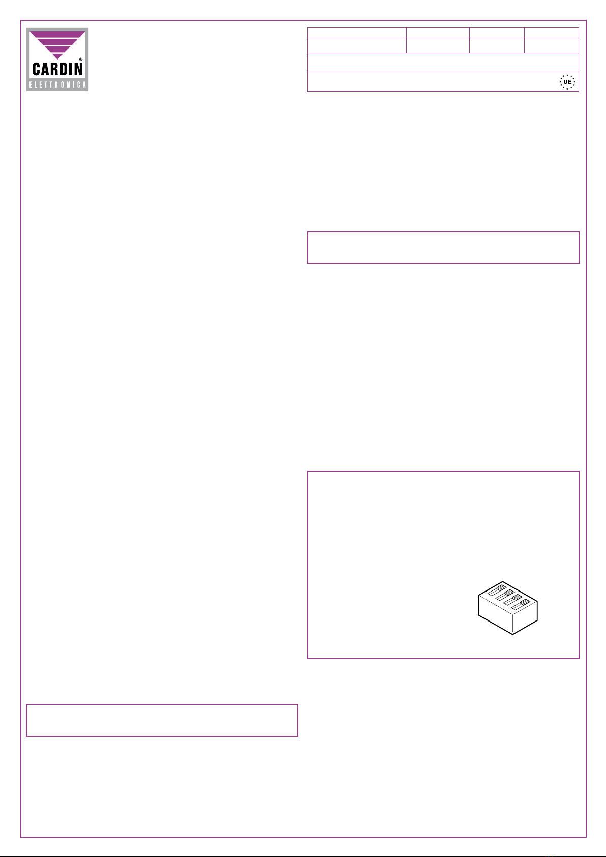
Die Funksteuerung kann zur gemeinsamen Betätigung mehrerer Motoren verwendet werden, indem die gleichen
Kanäle bei mehreren Funksteuerungn gespeichert werden. Die Tasten-Funktionen der Funksteuerung sind wie
in Abb. 3 angezeigt voreingestellt.
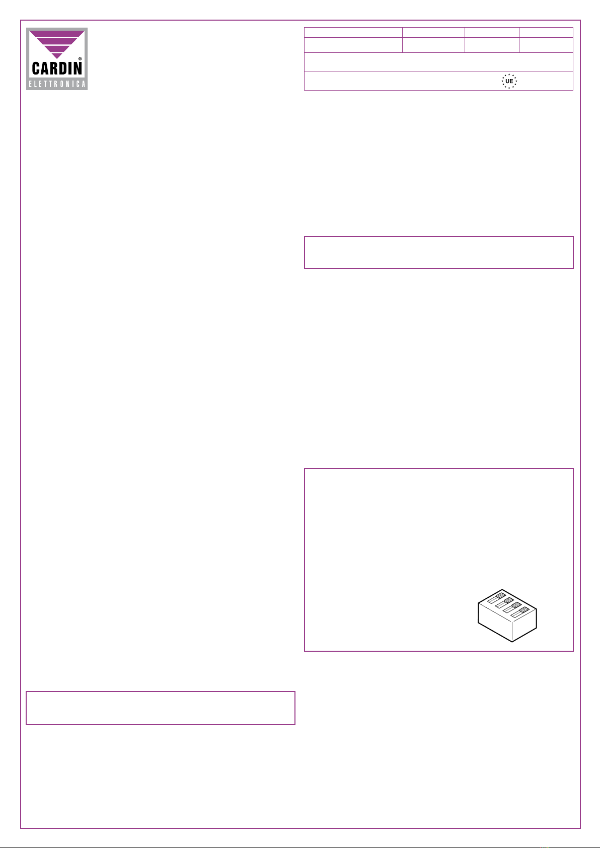
Sender-Versionen
TRQ449400 handsender 4 Tasten
TRQ44940M Funkdruckknopftafel zur Anbringung an der Wand 4 Tasten
Empfänger-Versionen
RP449RNA0 Funksteuerung RP449 mit Windgeschwindigkeitsmesser
Installation Empfänger - Antenne
Mindest- und Höchstreichweite der Funksteuerungen:
Unter Reichweite versteht sich der nutzbare Betriebsabstand zwischen Sender und Empfänger, deren Antenne im
freien Raum installiert und gemessen wurde. Daher steht die Reichweite in unmittelbarem Zusammenhang mit den
technischenEigenschaftendesSystems (LeistungundAnsprechempfindlichkeit)undverändertsichentsprechend
dem Aufstellungsort. Um einen optimalen Betrieb der Funksteuerung zu gewährleisten, sind die Installationsorte
für den Empfänger und die Antenne sorgfältig auszuwählen.
Es ist ratsam, den Empfänger in gebührendem Abstand zu Computersystemen, Alarmanlagen und anderen
möglichen Störungsquellen aufzustellen
(Eine unsachgemäße Aufstellung könnte den Betrieb teilweise gefährden).
Antenne
Die Installation der Antenne ist von äußerster Wichtigkeit; nachdem sie mit dem Empfänger verbunden ist, stellt
sie den Empfangspunkt für die Funksteuerung dar. Bei ihrer Installation ist folgendes zu beachten. Der Empfänger
ist mit einer eigenen Antenne ausgestattet, die aus einem Stück starren Drahtes besteht, der 170 mm lang ist.
AlternativkanneinepassendeAntenneANS400verwendetwerden,diemittelseinemKoaxialkabelRG58(Impedanz
50Ω) mit einer maximalen Länge von 15 m an den Empfänger angeschlossen wird. In diesem Fall sollte für einen
optimalen Betrieb der Funksteuerung der Installationsort sorgfältig ausgewählt werden.
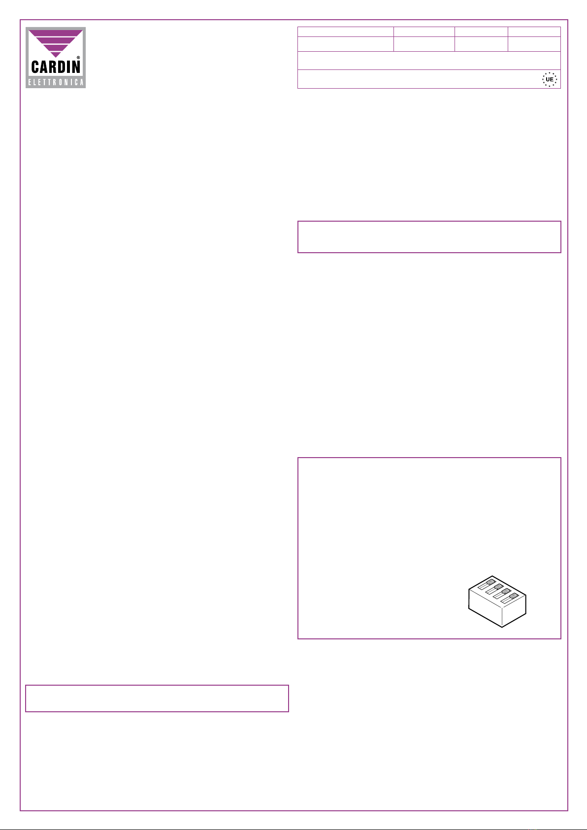
Sender
Der Sender ist vorkodifiziert und besitzt einen integrierten Schaltkreis, der im Werk schon mit einer für jeden
Sender einzigartigen Identifikationsnummer vorprogrammiert worden ist; alle für die Kodifizierung notwendigen
Parameter befinden sich in diesem integrierten Schaltkreis (es wird kein äußerer Speicher benutzt); dies macht
den Verwaltungsmechanismus der Kodifizierung wesentlich zuverlässiger und gestaltet das System sicherer. Der
Sender verfügt über einen Selbstausschaltmechanismus, der nach 25 Sekunden fortlaufender Aktivierung das
Gerät ausschaltet (Batteriestromersparnis).
• Diese Zeitspanne kann zwischen den einzelnen Sendern sehr unterschiedlich sein.
Empfänger
Die Installationsorte unter Berücksichtigung der Typologie und der Eigenschaften der Anlage auswählen.
Die Apparatur muss:
- in geschlossenen Räumen;
- vor Stößen und Beschädigungen geschützt;
- an einem für den Techniker zwecks Wartung leicht zugänglichen Ort untergebracht werden.
• Beide Befestigungsschrauben losschrauben und den Deckel anheben.
• Die beiden Befestigungspunkte (mit Hilfe der Schachtel) anzeichnen und das Gehäuse dann mit den beiden
selbstschneidenden Schrauben M4 und den entsprechenden Dübeln anbringen.
• Die beiden Kunststoffabdeckungen auf den Kabeleingängen entfernen.
Elektroanschluss
• Vor der Ausführung des Elektroanschlusses sicherstellen, dass:
- die auf dem Typenschild angegebene Spannung und Frequenz mit denen der elektrischen Stromversorgung
übereinstimmen;
- ein allpoliger Schalter mit einer Öffnungsweite zwischen den Kontakten von mindestens 3mm vor dem Strom-
kabeleinlass der Apparatur eingefügt ist;
- die Anschlusskabel vor mechanischer Beanspruchung geschützt sind.
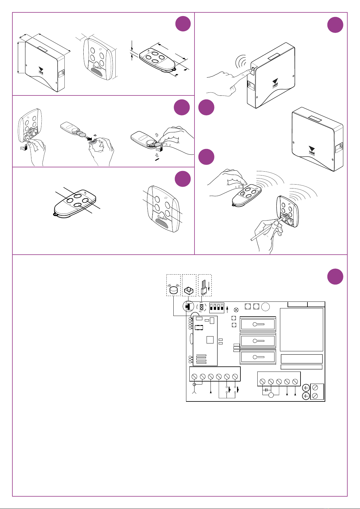
Codeverwaltung im Empfänger (Abb. 5)
Achtung! Vor der Speicherung des ersten Senders Speicher vorher vollkommen löschen.
Überprüfen, dass der Jumper "J1” eingesetzt ist (nur wenn dies der Fall ist, ist der Empfänger während
der Speicherung/Löschung der Codes zur akustischen Signalgebung befähigt).
Löschung aller Codes
1) Die Taste "P1" (Abb. 5) dreimal drücken und dann fortlaufend (für 5 Sekunden) gedrückt halten. Der Empfänger
gibt zu Anfang einen "Bip"-Dauerton und nach erfolgter Löschung einen in rascher Abfolge ertönenden "Bip"-
Ton von sich. Taste loslassen.
Speicherung eines Codes im Empfänger
1) Die Taste „P1" (Abb. 5) gedrückt halten. Der Empfänger gibt nun eine Reihe von regelmäßigen "Bip"-Tönen
von sich.
2) Den zu speichernden Kanal senden (Abb. 3, 4).
3) DerEmpfängergibtnuneineReihe vonin kürzerenAbständenerschallenden"Bip"-Tönenvonsich,was anzeigt,
dass der Kanal gespeichert worden ist. Die Taste "P1" nun loslassen. Jeder Code muss einzeln eingegeben
werden. Um den nächsten Code einzugeben, die Taste loslassen und die Punkte 1,2,3 wiederholen.
Falls der Code nicht gespeichert wird:
- Der übertragene Code existiert schon im Speicher.
- Der Speicher ist voll (mit 20 schon gespeicherten Sendern). In diesem Fall ist die Eingabe eines neuen Codes
nur dann möglich, wenn ein vorhandener Code oder der gesamte Speicher gelöscht wird (siehe Löschverfah-
ren).
Achtung: Wenn der Speicher voll besetzt ist, gibt der Summer für 5 Sekunden ein akustisches Signal von
sich.
Verfahren zur Löschung eines Codes im Empfänger
1) Die Taste "P1" zweimal drücken (Abb. 5) und dann gedrückt halten. Der Empfänger wird nun eine Reihe kurzer
"Bip"-Töne von sich geben.
2) Den zu löschenden Kanal für eine Dauer von mindestens 5 Sekunden senden. Der Empfänger gibt nun eine
Reihe von "Bip"-Tönen in kürzeren Abständen von sich, was anzeigt, dass der Kanal gelöscht worden ist.
Zwecks Löschung eines weiteren Kanals die Punkte 1 und 2 wiederholen.
Speicherung weiterer Kanäle über Funk (Abb. 4b)
Die Speicherung kann nur dann über Funk aktiviert werden (ohne das Empfängergehäuse zu öffnen), wenn
der Jumper "J1” eingesetzt worden ist (Abb. 5).
Achtung!BeijederEinstellungsänderung desJumpersmuss,damit diesewirksam wird,dieStromversorgung
des Empfängers ab- und wieder eingeschaltet werden.
1) Sicherstellen, ob der Jumper "J1" auf dem Empfänger eingesetzt ist.
2) Betätigen der Taste "MR" auf der Funksteuerung, bei der mindestens eine der Kanaltasten "A-B-C-D" schon
auf dem Empfänger gespeichert worden ist, wie in Abbildung "4b" angezeigt wird.
Anmerkung: Alle von der Funksteuerung erreichbaren Empfänger und die mindestens einen Kanal des Senders
gespeichert haben, aktivieren gleichzeitig den Summer.
3) Eine der Kanaltasten des Senders betätigen. Die Empfänger, die nicht den Code dieser Taste besitzen, schalten
sich ab und geben dabei einen 5 Sekunden dauernden "Bip"-Ton von sich. Die Empfänger, die stattdessen
den Code gespeichert haben, geben einen andersartigen, eine Sekunde dauernden "Bip"-Ton von sich und
begeben sich in den "funkgesteuerten" Speichermodus.
4) Eine der zu speichernden Kanaltasten auf dem Sender drücken. Bei erfolgter Speicherung gibt der Empfänger
2, eine halbe Sekunde lang dauernde Biptöne von sich. Danach ist der Empfänger bereit, einen anderen Code
zu speichern.
5) Um den Modus zu beenden, 3 Sekunden ohne einen Code zu speichern verstreichen lassen. Der Empfänger
gibt einen 5 Sekunden dauernden "Bip"-Ton von sich und beendet automatisch den "funkgesteuerten" Spei-
chermodus.
ACHTUNG: Der Funksteuerung kann die Betriebsfunktionen von 20 verschiedenen Sendern und somit max.
80 Kanaltasten speichern. Wenn also "über Funk" ein Kanalcode gespeichert wird, bestehen daher die drei
nachfolgenden Möglichkeiten:
• Es wurden weniger als 20 Sender gespeichert: Das Verfahren verläuft wie oben beschrieben weiter.
• Es sind schon 20 Sender gespeichert worden, aber es sind noch nicht alle Kanäle für jeden dieser Sender
gespeichert worden. Es können daher noch ein oder mehrere Kanäle nur für diese Sender gespeichert werden
(ein Kanal für einen einundzwanzigsten Sender kann nicht gespeichert werden). Das akustische Signal nach
dem Drücken der Taste "MR" wird das folgende sein: in rascher Abfolge ertönende "Bip"-Töne (Anzeige, dass
kein neuer Sender gespeichert werden kann) gefolgt von einem 1 Sekunde dauernden "Bip"-Ton (der anzeigt,
dass zur Speicherung über Funk fortgeschritten werden kann).
• Es sind alle Kanäle für die 20 Sender gespeichert worden: Der Speicher ist voll. Aus diesem Grund lässt der
Funksteuerung beim Drücken der Taste "MR" nur "Bip"-Töne in rascher Abfolge ertönen und tritt aus dem
Code-Programmiermodus aus.
Windgeschwindigkeitsmesser
Mit einem installierten Windgeschwindigkeitsmesser kann das automatische Schließen bei starkem Wind
programmiert werden. Der Dip-Schalter "D1" (Abb. 5) gestattet vier Wahlmöglichkeiten: 20-35-42 und 50
km/Std.BeiangeschaltetemWindgeschwindigkeitsmesser(beiWind)wirdderBetriebderFunksteuerungoder
der über Kabelverbindung laufenden Steuerung für 10 Minuten verhindert. Zur Empfindlichkeitseinstellung
während der Installation kann diese Blockierzeit annulliert werden, indem die Stromversorgung unterbrochen
unddannwiederhergestelltwird.IndiesemFallistes ratsam,zeitweiligdiezwangsweiseWiederverschließung
auszuschalten. (Dip 1 "ON" Abb. 5).
Wahlmöglichkeiten Dip-Schalter D1
Zwangsweise Wiederverschließung
Durch Einstellung des Dip 1 auf "OFF" wird diese Funktion befähigt. Sie besteht in der zwangsweisen
Schließung bei jedem Neustart des Funksteuerungs.
Dip 1 ON Stellt die zwangsweise Schließung beim Anschalten außer Dienst
Dip 2 ON Schließt die Funktion des Windgeschwindigkeitsmessers aus
Dip 3 OFF
Dip 4 OFF Windgeschwindigkeit 20 km/Std
Dip 3 OFF
Dip 4 ON Windgeschwindigkeit 35 km/Std
Dip 3 ON
Dip 4 OFF Windgeschwindigkeit 42 km/Std
Dip 3 ON
Dip 4 ON Windgeschwindigkeit 50 km/Std
TECHNISCHE DATEN
Empfänger
- Stromversorgung........................................................................................................................230Vac, 50-60Hz
- Speicherbare Kanäle ..........................................................................................................................................80
- Windgeschwindigkeit (wählbar).............................................................................................20-35-42-50 km/Std
- Betriebstemperatur.............................................................................................................................-20°...+60°C
- Schmelzsicherung ................................................................................................................. F 3.15A 250V (5x20)
Sender
- Sendefrequenz.................................................................................................................................... 433.92 MHz
- Sendefrequenztolleranz............................................................................................................................ ±30 kHz
- Scheinbare Strahlungsleistung.................................................................................... -10...-7dBm (100-200 µW)
- Strahlung der Oberwellenprodukte...........................................................................................<-54dBm (<4 nW)
- Modulation.................................................................................................................................................FM/FSK
- Modulation mit ∆F ....................................................................................................................................≤20 kHz
- Stromversorgung (Lithiumbatterie)........................................................................................................4xCR2016
- Stromaufnahme........................................................................................................................................... 35 mA
- Betriebstemperatur.............................................................................................................................-10°...+55°C
- relative Luftfeuchtigkeit ................................................................................................................................<95%
- Kodifizierungstyp.................................................................................................................................rolling code
- Anzahl aller Kombinationsmöglichkeiten (66 Bit).............................................................................................. 266
- Anzahl der Betriebsfunktionen (Kanäle)...............................................................................................................4
- Selbstausschaltung (Minimum) ............................................................................................... nach 25 Sekunden
MODELL DATUMART.-NR SERIE
Die Serie S449 entspricht den von der Bestimmung 99/05/CE festgelegten grundsätz-
lichen Anforderungen und bei ihr wurden die technischen Bezugsnormen angewandt.
Frequenzbereich: 433.92 für alle Länder der
}
}
}
}
1234
ON

ZVL413.01 S449
11-06-2001
RP449RN
CARDIN ELETTRONICA spa
Via Raffaello, 36- 31020 San Vendemiano (TV) Italy
Tel: +39/0438.404011-401818
Fax: +39/0438.401831
email (Europe): Sales.office@cardin.it
Http: www.cardin.it
Descripción
El sistema de radiomando S449 en "FM" consta de uno o más transmisores y de uno o más receptores que
se combinarán en función de las exigencias específicas de la instalación. La gama S449 emplea un sistema
de codificación de gran fiabilidad garantizada por el uso de códigos dinámicos. Por cada transmisión el
código cambia a base de un algoritmo que sólo el receptor puede reconocer y establecer si la transmisión
es correcta respecto al código original. El código es memorizado por radio en el receptor. En el receptor
se pueden memorizar hasta 20 transmisores diferentes por un total de 80 teclas de canales (máx.) que
siguen almacenados en la memoria incluso a falta de fluido eléctrico.
Importante: Puesto que por cada mando el código transmitido cambia, si la transmisión es interrumpida
por algún parásito, el receptor espera un código diferente, por tanto para restablecer el mando es necesario
soltar y volver a presionar la tecla del transmisor.
Descripción
El radioprogramador permite el mando a distancia de un motor monofásico de 230Vac, 50-60Hz, 400W y
su mejor utilización es para el control de persianas y cortinas automáticas.
El radioprogramador dispone de dos entradas en la bornera para los mandos independientes de apertura
y cierre, según dos modalidades posibles:
1) Manteniendooprimidoelbotón"TA"o "TC"porunplazomayorque1segundo,el motorestarácontrolado
"con la modalidad manual"; el bloqueo se consigue soltando el botón.
2) Oprimiendo por un breve plazo (menor que un segundo) el botón "TA" o "TC", el motor estará controlado
"en automático" y se parará al final de la maniobra (tiempo máximo de trabajo: 1,5 minutos aproxima-
damente, no ajustable). Para bloquear el motor, oprimir al mismo tiempo ambos botones.
Para el accionamiento común de más motores se podrá utilizar el radiomando, recordándose de memorizar
los mismos canales en más radioprogramadores.
Las funciones de los botones del radiomando están prefijadas, así como está indicado en la figura 3.
Versiones de transmisores
TRQ449400 Transmisores de bolsillo 4 teclas
TRQ44940M Botonera radio para fijación en la pared 4 teclas
Versiones de receptores
RP449RNA0 Radioprogramador RP449 con anemómetro
Instalación receptor-antena
Alcance mínimo y máximo de los radiomandos:
Por alcance se entiende la distancia útil de funcionamiento entre el transmisor y el receptor con la antena
instalada y medida al aire libre. Por tanto el alcance depende de las características técnicas del sistema
(potencia y sensibilidad) y varía en función de las características del lugar de emplazamiento. Para obtener
el mejor funcionamiento del radiomando es necesario elegir con sumo esmero los sitios de instalación
del receptor y de la antena. Es buena regla colocar el receptor a cierta distancia de las redes de sistemas
computarizados, instalaciones de alarma y otras fuentes de perturbaciones posibles.
(Su colocación incorrecta podría perjudicar parcialmente al funcionamiento).
Antena
La instalación de la antena es fundamental; conectada al receptor representa el punto de recepción del
radiomando. Durante su instalación hay que cumplir las instrucciones siguientes.
El receptor está dotado de antena propia, que consta de un trozo de hilo rígido, de 170 mm. de largo.
EnalternativaesposibleutilizarlaantenaacordadaANS400a conectaralreceptormedianteuncablecoaxial
RG58 (impedancia 50Ω) de 15 m. de largo como máximo. En tal caso para obtener el mejor funcionamiento
del radiomando es necesario elegir con sumo esmero los sitios de instalación.
Transmisor
El transmisor está codificado previamente y utiliza un circuito integrado programado en fábrica, con un
número identificativo único para cada transmisor;
todos los parámetros necesarios para la codificación están en este circuito integrado (no se utiliza una
memoria exterior): esto vuelve mucho más fiable el método de gestión de la codificación, y más seguro
el entero sistema. El transmisor posee un mecanismo de auto-apagado tras 25 segundos de activación
continua (para limitar el consumo de la batería).
• Este plazo puede variar significativamente de un transmisor a otro.
Receptor
En función de la tipología y de las características de la instalación, determinar el punto donde se va a
colocar el equipo. El equipo se tendrá que disponer:
- en un ambiente interior;
- protegido contra los golpes y el manejo;
- en una posición de fácil acceso para el técnico, para las operaciones de mantenimiento.
• Aflojar los dos tornillos de fijación y levantar la tapa.
• Marcar (con el auxilio de la caja) los dos puntos de fijación y fijar el contenedor utilizando dos tornillos
autorroscantes M4 y los tacos correspondientes.
• Quitar las dos protecciones de plástico en la entrada de los cables.
Conexión eléctrica
• Antes de realizar la conexión eléctrica, comprobar que:
- la tensión y la frecuencia indicadas en la placa de características coincidan con las de la instalación de
alimentación;
- un interruptor omnipolar con apertura entre los contactos de al menos 3 mm esté incorporado antes
del equipo;
- los cables de conexión estén protegidos contra los esfuerzos mecánicos.
Gestión de los códigos en el receptor (fig. 5)
¡Cuidado! Antes de proceder a la primera memorización de los transmisores, hace falta borrar ente-
ramente la memoria.
Comprobar que el "jumper” "J1” esté conectado ( sólo de esta manera el receptor podrá efectuar la
señal acústica durante la memorización / cancelación de los códigos ).
Para borrar todos los códigos:
1) Oprimir tres veces el botón "P1" (fig. 5) y mantenerlo presionado (durante 5 segundos como mínimo). El
receptor al principio emite un "toque" continuo, y una vez efectuada la cancelación emite una secuencia
rápida de " toques". Soltar el botón.
Memorización de un código en el receptor
1) Presionar el botón "P1" (fig. 5) y mantenerlo oprimido: el receptor emitirá una serie de "toques" a
intervalos regulares.
2) Transmitir el canal a memorizar (fig. 3, 4).
3) El receptor emitirá una serie de "toques" a intervalos más cortos indicando que el canal ha sido
memorizado. Soltar el botón "P1". Es posible introducir un solo código a la vez, para introducir el código
siguiente soltar el botón y repetir los puntos 1, 2 y 3.
RADIOPROGRAMADOR POR CODIGOS DINAMICOS PARA CORTINAS
MODELO FECHACODIGO SERIE
La serie S449 es conforme con los requisitos esenciales dispuestos por la
directiva 99/05/CE y con ésta se relacionan las normas técnicas de referencia.
Frecuencia: 433.92MHz para los países de l
}
}
}
}
1234
ON
Si el código no se memoriza:
- El código transmitido ya existe en la memoria.
- La memoria está completa (con 20 transmisores ya memorizados). En tal caso es posible introducir
un nuevo código tan sólo borrando un código existente o la entera memoria (ver el procedimiento de
borrado).
Cuidado: cuando la memoria está totalmente ocupada, el avisador acústico emite una señal acústica
durante unos 5 segundos.
Procedimiento de borrado de un código en el receptor:
1) Oprimir dos veces el botón "P1" (fig. 5) y mantenerlo presionado. El receptor emitirá una serie de
"toques" de breve duración.
2) Transmitir el canal a borrar (durante 5 segundos como mínimo). El receptor emitirá una serie de "toques"
a intervalos más cortos indicando que el canal ha sido borrado. Para borrar el código siguiente repetir
los puntos 1 y 2.
Memorización de otros canales vía radio (fig. 4b)
La memorización se puede activar vía radio (sin abrir la caja donde está alojado el receptor) solamente
si el jumper "J1" está conectado (fig. 5).
¡Cuidado! Para que sea factible cualquier cambio en la programación del "jumper” es necesario quitar
y volver a dar la corriente al receptor.
1) Comprobar que el jumper "J1" está conectado en el receptor.
2) Utilizando un radiomando donde al menos una de las teclas de canal "A-B-C-D" ya está memorizada
en el receptor, activar la tecla "MR" según lo que está representado en la figura "4b".
Nota: todos los receptores alcanzables por la emisión del radiomando, y que tengan al menos un canal
del transmisor memorizado, activarán al mismo tiempo el avisador acústico.
3) Activar una de las teclas de canal del transmisor. Los receptores que no tienen el código de esa tecla
se desactivarán con la emisión de un "toque" de 5 segundos de duración; en cambio el que tiene el
código emitirá otro "toque" de un segundo de duración, entrando efectivamente en la modalidad de
memorización "vía radio".
4) Oprimir una tecla de canal en el transmisor a memorizar; realizada la memorización, el receptor emitirá
2 "toques" de medio segundo, después de lo cual estará listo para memorizar otro código.
5) Para salir de esta modalidad, dejar pasar 3 segundos sin memorizar códigos. El receptor emitirá un
"toque" de 5 segundos y saldrá de la modalidad.
CUIDADO: el radioprogramador puede memorizar las funciones de 20 transmisores diferentes, por
tanto 80 teclas de canales como máximo; al memorizar "vía radio" un código de canal, hay las tres
posibilidades siguientes:
• Se han memorizado menos de 20 transmisores: el procedimiento sigue adelante como está indicado
arriba.
• Ya se han memorizado 20 transmisores, pero no se han memorizado todos los canales para cada
uno de ellos: entonces será posible almacenar en la memoria uno o más canales solamente de estos
transmisores (no se puede memorizar un canal del vigésimo primero transmisor). La indicación acústica,
después de haber oprimido la tecla "MR", será la siguiente: secuencia rápida de "toques" (que señala
la imposibilidad de memorizar un nuevo TX) seguida de un "toque" de 1 segundo de duración (que
señala la posibilidad de proceder a la memorización vía radio.
• Se han memorizado todos los canales para los 20 transmisores: la memoria está totalmente ocupada,
por los cual, al oprimir la tecla "MR" el radioprogramador realizará la secuencia de "toques" rápidos
y saldrá de la modalidad de programación de los códigos.
Anemómetro
Con el anemómetro instalado se puede programar el cierre automático en condiciones de fuerte
viento. El Dip-switch "D1" (fig. 5) tiene cuatro niveles de selección: 20-35-42 y 50 km/hora. Con el
anemómetro activado (situación de viento) está deshabilitada la función de radiomando o mandos vía
cable durante 10 minutos. Para efectuar la regulación de la sensibilidad durante la fase de instalación
es posible anular este plazo de bloqueo cortando y volviendo a restablecer la alimentación: en tal caso
será oportuno desconectar temporalmente el cierre forzado (Dip 1 "ON" fig. 5).
Selecciones Dip-switch D1
Cierre forzado
Seleccionando el Dip 1 en "OFF" se habilita esta función, que consiste en el cierre forzado a cada
rearranque del radioprogramador.
Dip 1 ON Deshabilita el cierre forzado al acto del encendido
Dip 2 ON Deshabilita la función anemómetro
Dip 3 OFF Velocidad viento 20 km/hora
Dip 4 OFF
Dip 3 OFF Velocidad viento 35 km/hora
Dip 4 ON
Dip 3 ON Velocidad viento 42 km/hora
Dip 4 OFF
Dip 3 ON Velocidad viento 50 km/hora
Dip 4 ON
CARACTERISTICAS TECNICAS
Receptor
- alimentación .................................................................................................................230V ac, 50-60 Hz
- canales memorizables............................................................................................................................80
- velocidad viento (seleccionable) .............................................................................20-35-42-50 km/hora
- temperatura de funcionamiento............................................................................................-20°...+60 °C
- fusible ........................................................................................................................ F 3.15A 250V (5x20)
Transmisor
- frecuencia portadora.............................................................................................................. 433.92 MHz
- tolerancia de la frecuencia portadora .......................................................................................... ±30 kHz
- potencia aparente irradiada ............................................................................-10…-7dBm (100-200 µW)
- potencia aparente de los productos armónicos...........................................................<-54dBm (<4 nW)
- modulación................................................................................................................................... FM/FSK
- modulación con ∆F .......................................................................................................................≤20 kHz
- alimentación (batería de litio) ..................................................................................................2 x CR2032
- absorción......................................................................................................................................... 35 mA
- temperatura de funcionamiento........................................................................................... - 10…+55 °C
- humedad relativa..............................................................................................................................<95%
- tipo de código .........................................................................................................................rolling code
- n° de combinaciones totales (66 bit)......................................................................................................2
66
-
n° de funciones (canales).........................................................................................................................4
- autoapagado .....................................................................................................después de 25 segundos

TRS44940M
02-07-2001
DM0550
CAMBIO BATTERIA
Description :
Product Code :
Date :
Drawing number :
P.J.Heath
CARDIN ELETTRONICA S.p.A - 31020 San Vendemiano (TV) Italy - via Raffaello, 36 Tel: 0438/401818 Fax: 0438/401831
Draft :
All rights reserved. Unauthorised copying or use of the information contained in this document is punishable by law
TRS44940M
02-07-2001
DM0552
SELEZIONE CANALI
Description :
Product Code :
Date :
Drawing number :
P.J.Heath
CARDIN ELETTRONICA S.p.A - 31020 San Vendemiano (TV) Italy - via Raffaello, 36 Tel: 0438/401818 Fax: 0438/401831
Draft :
All rights reserved. Unauthorised copying or use of the information contained in this document is punishable by law
CH A
CH B
CH C
CH D
RADIO RENO S449
Programmazione Radio Reno
RXPR RENO
20-07-01
DM0555 Description :
Product Code :
Date :
Drawing number :
P.J.Heath
CARDIN ELETTRONICA S.p.A - 31020 San Vendemiano (TV) Italy - via Raffaello, 36 Tel: 0438/401818 Fax: 0438/401831
Draft :
All rights reserved. Unauthorised copying or use of the information contained in this document is punishable by law
MR
PROCEDURA DI MEMORIZZAZIONE/CANCELLAZIONE
CHANNEL MEMORISATION/CANCELATION PROCEDURE
PROCÉDÉ DE MÉMORISATION/EFFACEMENT
SPEICHER-/LÖSCHUNGSVERFAHREN
PROCEDIMIENTO DE ALMACENAMIENTO/BORRADO
CH A
CH B
CH C
CH D
SRLRZIONI CANALE 4 TASTI
TRQ449200
13-04-2001
DM0524 Description :
Product Code :
Date :
Drawing number :
P.J.Heath
CARDIN ELETTRONICA S.p.A - 31020 San Vendemiano (TV) Italy - via Raffaello, 36 Tel: 0438/401818 Fax: 0438/401831
Draft :
All rights reserved. Unauthorised copying or use of the information contained in this document is punishable by law
DIMENSIONI D'INGOMBRO - OVERALL DIMENSIONS - DIMENSIONS
D'ENCOMBREMENT- AUSSENABMESSUNGEN - DIMENSIONES DEL
ESPACIO OCUPADO
CAMBIO BATTERIA - CHANGING THE BATTERY - REMPLACEMENT DE
LA PILE - BATTERIEWECHSEL - SUSTITUCIÓN DE LA PILA
1
2
SELEZIONE DEI CANALI - CHANNEL SELECTION - DISPOSITION DES CANAUX
- ANORDNUNG DER KANÄLE - DISPOSICION DE LOS CANALES 3
72
11
34
DIMENSIONI D'INGOMBRO
TRQ449200
13-04-2001
DM0523 Description :
Product Code :
Date :
Drawing number :
P.J.Heath
CARDIN ELETTRONICA S.p.A - 31020 San Vendemiano (TV) Italy - via Raffaello, 36 Tel: 0438/401818 Fax: 0438/401831
Draft :
All rights reserved. Unauthorised copying or use of the information contained in this document is punishable by law
Cambio batteria 2
TRQ449200
13-04-2001
DM0527 Description :
Product Code :
Date :
Drawing number :
P.J.Heath
CARDIN ELETTRONICA S.p.A - 31020 San Vendemiano (TV) Italy - via Raffaello, 36 Tel: 0438/401818 Fax: 0438/401831
Draft :
All rights reserved. Unauthorised copying or use of the information contained in this document is punishable by law
+
4
Legenda
1 Centrale antenna (filo rigido da 17 cm in dotazione)
2 Massa antenna RX radio da usare con antenna esterna (cavo coassiale RG58 50Ω)
3 Ingresso anemometro
4 Comune per tutti gli ingressi di comando
5 Ingresso tasto di chiusura (contatto N.A.)
6 Ingresso tasto di apertura (contatto N.A.)
7 Uscita motore (chiusura)
8 Uscita motore (apertura)
9 Uscita motore (comune)
10-11 Alimentazione radioprogrammatore 230Vac 50-60Hz
12 Ingresso terra alimentazione
13 Uscita terra motore
B1 Buzzer per segnalazione sonora
D1 Dip-switch per selezione velocità vento
J1 Jumper per "memorizzazione remota"
L1 Led scheda alimentata
P1 Pulsante di programmazione codici
Legend
1 Antenna pole (17 cm piece of rigid wire supplied)
2 Antenna braid connection for an external antenna (coaxial cable RG58 50Ω)
3 Anemometer input
4 Common for all inputs
5 Closing button input (N.O. contact)
5 Opening button input (N.O. contact)
7 Motor output (closing
8) Motor output (opening)
9 Motor output (neutral)
10-11 Radio programmer power supply 230Vac 50-60Hz
12 Power supply earth connection
13 Motor output earth connection
B1 Indicator buzzer
D1 Wind speed selection dip-switch
J1 Remote memorisation jumper
L1 Power on Led
P1 Programming button
2 3 4 5 6
DC0337
CS1097
1
F3.15A
ANEM
8 9 10 11
7
13
12
TA M
CH.
COM
AP.
c
230V~
4
3
21
ON
D1
J1
P1
L1
TC LN
B1
COLLEGAMENTO RADIO RENO
Radio Reno S449
11-06-2001
DC0337 Description:
Product Code :
Date :
Drawing number :
P.J.Heath
CARDIN ELETTRONICA S.p.A - 31020 San Vendemiano (TV) Italy - via Raffaello, 36 Tel: 0438/401818 Fax: 0438/401831
Draft :
All rights reserved. Unauthorised copying or use of the information contained in this document is punishable by law
RADIO RENO S449
Bip…Bip…Bip
Programmazione Radio Reno
RXPR RENO
11-06-01
DM0537 Description :
Product Code :
Date :
Drawing number :
P.J.Heath
CARDIN ELETTRONICA S.p.A - 31020 San Vendemiano (TV) Italy - via Raffaello, 36 Tel: 0438/401818 Fax: 0438/401831
Draft :
All rights reserved. Unauthorised copying or use of the information contained in this document is punishable by law
RADIO RENO S449
Dimensioni di ingombro
RXPR RENO
11-06-01
DM0538 Description :
Product Code :
Date :
Drawing number :
P.J.Heath
CARDIN ELETTRONICA S.p.A - 31020 San Vendemiano (TV) Italy - via Raffaello, 36 Tel: 0438/401818 Fax: 0438/401831
Draft :
All rights reserved. Unauthorised copying or use of the information contained in this document is punishable by law
85
20
120
5
CHA = APRE-OPEN-OUVRE-ÖFFNEN-APERTURA
CHB = CHIUDE-CLOSE-FERME-SCHLIESSEN-CIERRE
CHC = STOP
CHD = SEQUENZIALE-SEQUENTIAL-SÉQUENTIEL-SEQUENTIELL-SECUENCIA
(APRE/STOP/CHIUDE/STOP) - (OPEN/STOP/CLOSE/STOP) - (OUVRE/STOP/FERME/STOP)
(ÖFFNEN/STOP/SCHLIESSEN/STOP) - (APERTURA/STOP/CLOSE/CIERRE)
4a
4b
COLLEGAMENTI RADIO PROGRAMMATORE - RADIOPROGRAMMER CONNECTIONS
CONNEXIONS DU RADIOPROGRAMMATEUR - ANSCHLÜSSE AM FUNKSTEUERUNG - CONEXIONES RADIOPROGRAMADOR
Nomenclature
1 Âme antenne (fil rigide de 17 cm fourni en dotation)
2 Masse antenne RX radio à utiliser avec antenne externe
(câble coaxial RG58 50Ω)
3 Entrée anémomètre (en option)
4 Communs pour toutes les entrées
5 Entrée bouton de fermeture (contact N.O.)
6 Entrée bouton d'ouverture (contact N.O.)
7 Sortie moteur (fermeture)
8 Sortie moteur (ouverture)
9 Sortie moteur (commun)
10-11 Alimentation radioprogrammateur 230V ac 50-60Hz
12 Entrée terre alimentation
13 Sortie terre moteur
B1 Avertisseur sonore
D1 Dip-switch pour sélections Vitesse du vent
J1 Cavalier pour la "mémorisation à distance”
L1 Led carte alimentée
P1 Bouton de programmation
Legende
1 Innenleiter Antenne (mitgeliefertes starres Kabel 17 cm)
2 Außenleiter Funkantenne RX mit externer Antenne
(Koaxialkabel RG58 50Ω) zu verwenden
3 Eingang Windgeschwindigkeitsmesser
4 Gemeinsame Anschlüsse für alle Eingänge
5 Eingang Schließtaste (Kontakt Einschaltglied)
6 Eingang Öffungstaste (Kontakt Einschaltglied)
7 Ausgang Motor (Schließen)
8 Ausgang Motor (Öffnen)
9 Ausgang Motor (Gemeinsam)
10-11 Stromversorgung Funksteuerung 230Vac 50-60Hz
12 Eingang Erdung Stromversorgung
13 Ausgang Erdung Motor
B1 Summer zur akustischen Signalisierung.
D1 Wahl-Dip-Schalter Windgeschwindigkeit
J1 Jumper für "ferngesteuerte Speicherung".
L1 LED Stromversorgung Karte.
P1 Programmiertaste
Leyenda
1 Central antena (cable rígido de 17 cm. suministrado)
2 Masa antena RX radio a utilizar con antena exterior
(cable coaxial RG58 50Ω)
3 Entrada anemómetro (opcional)
4 Comunes para todas las entradas
5 Entrada botón de cierre (contacto N.A.)
6 Entrada botón de apertura (contacto N.A.)
7 Salida motor (cierre)
8 Salida motor (apertura)
9 Salida motor (común)
10-11 Alimentación radio programador 230Vac 50-60Hz
12 Entrada tierra alimentación
13 Salida tierra motor
B1 Avisador acústico
D1 Dip-switch para selecciones velocidad viento
J1 Jumper para la memorización vía radio
L1 Piloto de alimentación
P1 Tecla de programación
TRS44940M
02-07-2001
DM0549
DIMENSIONI D'INGOMBRO
Description :
Product Code :
Date :
Drawing number :
P.J.Heath
CARDIN ELETTRONICA S.p.A - 31020 San Vendemiano (TV) Italy - via Raffaello, 36 Tel: 0438/401818 Fax: 0438/401831
Draft :
All rights reserved. Unauthorised copying or use of the information contained in this document is punishable by law
72
15
72
Cambio batteria 1
TRQ449200
13-04-2001
DM0526 Description :
Product Code :
Date :
Drawing number :
P.J.Heath
CARDIN ELETTRONICA S.p.A - 31020 San Vendemiano (TV) Italy - via Raffaello, 36 Tel: 0438/401818 Fax: 0438/401831
Draft :
All rights reserved. Unauthorised copying or use of the information contained in this document is punishable by law
Other manuals for S449
2
This manual suits for next models
4
Table of contents
Languages:
Other Cardin Motherboard manuals
Popular Motherboard manuals by other brands

Force Computers
Force Computers SPARC/CPU-5TE installation guide

Holtek
Holtek CPCB48MIO0001A Reference manual

Intel
Intel BLKD915PBLL - LGA775 800FSB 4DDR2 Audio Lan 1394a SATA Raid ATX 4PCI 10Pack... Technical product specification

IEI Technology
IEI Technology NOVA-7800 user manual

Biostar
Biostar TA770 A2 Bios setup manual

Asus
Asus A55BM-PLUS user manual