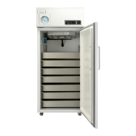
Cardinal Health 20EFEECAA User manual

1
Cardinal Health Brand
Refrigerators and Freezers
Installation and Operation Manual
Explosion-Proof Flammable Material Storage General Purpose
20EFEECAA
20EREECAA 20FFEECAA
20FREECAA
18LCEECAA
20LFEECAA
17LREECAA
326702H01 Rev C
20LREECAA

2
Table of Contents
Safety Information........................................................................................................................................................ 3
Alert Signals ................................................................................................................................................................. 3
Intended Use Statement .............................................................................................................................................. 4
Explosion-Proof Refrigerators and Freezers................................................................................................................ 5
Overview ...................................................................................................................................................................... 5
MODEL 20EREECAA .................................................................................................................................................. 6
MODEL 20EFEECAA................................................................................................................................................... 6
Flammable Materials Storage Refrigerators and Freezers.......................................................................................... 7
Overview ...................................................................................................................................................................... 7
MODEL 20FREECAA ................................................................................................................................................ ..8
MODEL 20FFEECAA................................................................................................................................................. ..8
General-Purpose Laboratory Refrigerators/Freezers ................................................................................................ ..9
Overview ......................................................................................................................................................................9
MODEL 20LREECAA................................................................................................................................................. 10
MODEL 20LFEECAA................................................................................................................................................. 10
MODEL 17LREECAA................................................................................................................................................. 11
MODEL 18LCEECAA................................................................................................................................................. 11
Unpacking and Installation.........................................................................................................................................12
Shipping Carton .........................................................................................................................................................12
Unpacking .................................................................................................................................................................. 12
Location...................................................................................................................................................................... 12
Clearance...................................................................................................................................................................12
Installation..................................................................................................................................................................14
Electrical.....................................................................................................................................................................14
Be Advised.................................................................................................................................................................14
How to Seal Killark® Box Conduit with Fiber and Sealing Compound to Help Protect Against Explosions
(Explosion-Proof Units Only):.....................................................................................................................................15
Operation ...................................................................................................................................................................18
Environmental Operating Conditions .........................................................................................................................18
Start-Up Procedure ....................................................................................................................................................18
Restart Procedure......................................................................................................................................................18
How to Save Energy ..................................................................................................................................................24
Safety Tips .................................................................................................................................................................24
Material Compatibility.................................................................................................................................................25
Troubleshooting .........................................................................................................................................................26
Maintenance...............................................................................................................................................................27
Cleaning of Units........................................................................................................................................................27
Interior/Exterior and Door Gaskets ............................................................................................................................27
Condenser..................................................................................................................................................................27
Manual Defrost Procedure .........................................................................................................................................28
Replacement Parts..................................................................................................................................................... 29
Ordering Procedures..................................................................................................................................................30
13 Month Limited Warranty........................................................................................................................................ 31
WEEE Compliance............. ........................................................................................................................................32

3
Safety Information
Thank you for selecting Cardinal Health products for your equipment needs. These instructions contain
important operating and safety information. The user must carefully read and understand these instructions
before using the unit. Your unit has been designed to optimize function, reliability, safety and ease of use. It
is the user’s responsibility to install the unit in conformance with local electrical codes.
Alert Signals
DANGER RISK OF CHILD ENTRAPMENT
Before you throw away your old refrigerator or freezer:
Take off doors
Leave the shelves in the place so that children may not easily climb inside.
If the equipment is used in a manner not specified by the manufacturer, the
protection provided by the equipment may be impaired.
ON
OFF
Safety Alert
Important operating instructions. To reduce the risk of injury or
poor performance of the unit read the user manual before
putting the equipment into operation.
WARNING
Indicates an immediately hazardous situation, which if not
avoided, will result in death or serious injury.
CAUTION
Indicates an immediately hazardous situation, which if not
avoided, may result in minor to moderate injury.
(No symbol)
CAUTION
(Without Safety Alert Symbol) indicates a situation that may
result in property damage.
Shock Hazard
Use of this equipment involves power supplies which convert
line voltage to low voltage power. Do not modify or use power
supplies other than OEM equipment. Connection of the power
supply may require a properly grounded receptacle. Potential
for electrical shock or equipment damage exists if precautions
are not followed.
Frost bite/ Low
Temperature Avoid contact with cold freezer surfaces potential for cold
burns or skin sticking to cold surfaces.

4
Intended Use Statement
The Refrigerators/Freezers described in this manual are for professional use only. These
products are intended for use in research for the storage of samples or inventory in the
following temperature ranges :
Refrigerators +1°C to +12°C
Freezers -12°C to -20°C
Only Explosion Proof Units or Flammable Material Storage Units are to
be used for the storage of flammable inventory/samples.
These are not considered medical devices and have therefore not been registered with a
medical device regulatory body (e.g. FDA): that is, it has not been evaluated for the storage
of samples for diagnostic use or for samples to be re-introduced to the body.

5
Explosion-Proof
Refrigerators and Freezers
Overview
Conventional refrigerators and freezers are not suitable for storing
flammable materials. Such units have components in their electrical
and refrigeration systems that can trigger explosions of flammable air-
vapor mixtures inside the unit and/or in the immediate surrounding
area.
The Authority having Jurisdiction (AHJ) determines if work areas are
designated as a hazardous location with respect to the presence of
flammable gases or vapours. Such locations are defined in (National
Fire Protection Agency) NFPA 70 Articles 500-501 and OSHA 29
CFR1910.307. Some of these classified areas are expected to
experience concentrations of flammable gases and/or vapors at or
above their lower flammability limits for extended periods of time.
The construction of our explosion-proof units has been evaluated by
Underwriters Laboratories (UL) and are suitable for use in classified
areas requiring Class I, Groups C and D* protected equipment. The
electrical components such as thermostats, wiring, splices, relays and
compressor motors on explosion-proof units are safely housed within
explosion-proof enclosures and conduit. Compressor surface
temperatures have been evaluated and determined to remain below the
flash point of materials found in Class I, Groups C and D.
All models have heavy-gauge, rigid, steel construction with a durable
enamel finish. Interiors have HIPS plastic construction. Each unit is
insulated throughout for energy-efficient operation.
These units are ideal for storing ethyl ether, acetone, alcohol,
benzene, gasoline, hexane, lacquer solvent vapors, naphtha, along
with many other potentially hazardous materials.
*The notation Class I, Groups C and D is an accepted abbreviation for
Class I, Div 1, Groups C and D.

6
EXPLOSION-PROOF UNITS
MODEL 20EREECAA MODEL 20EFEECAA
33" Wide, 33" Wide,
Refrigerator Freezer
Features: Features:
•
Overall 21Cu. ft.
•
Overall 21Cu. ft.
•
Four shelves (non-adjustable)
•
Four shelves (non-adjustable)
•
Manual defrost
•
Manual defrost
•
HIPS Plastic interior
•
HIPS Plastic interior
•
White color
•
White color
Model
Total Vol.
Exterior Dimensions
Cu. Ft.
H x W x D inches
20EREECAA
21
66”x33”x27.5”
(167.6x83.8x69.8 cm)
20EFEECAA
21
66”x33”x27.5”
(167.6x83.8x69.8 cm)
Model
Electrical Characteristics
Temp.
Volts/Hz, Amps
Range ° C (° F)
20EREECAA
115/60, 3.0
1˚ to 12˚
(34˚to 54˚)
20EFEECAA
115/60, 3.0
-20˚ to -12˚
(-4˚to 10˚)
NOTE: Amps listed are at normal run mode, starting amps may be higher.

7
Flammable Materials Storage
Refrigerators and Freezers
Overview
Conventional refrigerators and freezers are not suitable for
storing flammable materials. Such units have components in
their electrical and refrigeration systems that can trigger
explosions of flammable air-vapor mixtures inside the unit.
Flammable Materials Storage (FMS) refrigerators/freezers are
designed for use in locations, which are not classified by the
Authority Having Jurisdiction (AHJ) as hazardous.
Under normal operating conditions the build up or
presence of flammable vapors will not occur in the
environment external to the unit.
FMS units are NOT designed for use in Class I, Groups
C and D environments, which require an Explosion-
Proof Refrigerator/Freezer.
FMS units are designed and evaluated by Underwriters
Laboratories (UL) to meet the requirements of the National Fire
Protection Association Standards Nos. 45, 70 and 99. These
units have no internal electrical components that could trigger an
explosion or fire of hazardous materials inside the unit.
These units are ideal for storing cyclopropane, ethyl ether,
ethylene, acetone, alcohol, benzene, butane, gasoline, hexane,
lacquer solvent vapors, naphtha, natural gas or propane along
with many other potentially hazardous materials.
All models have heavy-gauge, rigid, steel construction with a
durable enamel finish. Interiors have HIPS plastic construction.
Each unit is insulated throughout for energy-efficient operation.
WARNING: DO NOT store flammable materials in
General Purpose Laboratory Refrigerator / Freezers.
Risk of explosion, fire and injury may occur.
For flammable materials use either a Flammable
Material Storage Unit or an Explosion Proof Unit.

8
MODEL 20FREECAA
33" Wide,
Refrigerator
Features:
•Overall 21cu. ft.
•Four shelves (non-adjustable)
•Manual defrost
•HIPS Plastic interior
•White color
FLAMMABLE MATERIALS STORAGE UNITS
MODEL 20FFEECAA
33" Wide,
Freezer
Features:
•Overall 21cu. ft.
•Four shelves (non-adjustable)
•Manual defrost
•HIPS Plastic interior
•White color
Model
Total Vol.
Exterior Dimensions
Cu. Ft.
H x W x D inches (cm)
20FREECAA
21
66” x 33” x 27.5”
(167.6 x 83.8 x 69.8 cm)
20FFEECAA
21
66” x 33” x 27.5”
(167.6 x 83.8 x 69.8 cm)
Model
Electrical Characteristics
Temp.
Volts/Hz, Amps
Range °C (°F)
20FREECAA
115/60, 3.0
1˚ to 12˚
(34˚to 54˚)
20FFEECAA
115/60, 3.0
-20˚ to -12˚
(-4˚to 10˚)
NOTE: Amps listed are at normal run mode, starting amps may be higher.

9
General-Purpose Laboratory
Refrigerators/Freezers
Overview
These are general-purpose units available in all
refrigerator, all freezer and combination
refrigerator/freezer models. These units are
intended for basic laboratory use only. Storage of
high-value, life science materials or clinical biological
materials may require alarm, monitoring, back-up and
temperature performance features. The need to add
these features should be determined by your
industrial hygienist or safety officer. These units are
not suitable for corrosive environments.
WARNING: DO NOT store flammable materials in
General Purpose Laboratory Refrigerator / Freezers.
Risk of explosion, fire and injury may occur.
For flammable materials use either a Flammable
Material Storage Unit or an Explosion Proof Unit.

10
GENERAL-PURPOSE LABORATORY REFRIGERATORS/FREEZERS
MODEL 20LREECAA
33" Wide,
Refrigerator
Features:
•Overall 21cu. ft.
•Four shelves
(adjustable)
•HIPS Plastic interior
•White color
MODEL 20LFEECAA
32" Wide,
Freezer
Features:
•Overall 21 cu. ft.
•Four shelves (non-adjustable)
•Manual defrost
•HIPS Plastic interior
•White color
Model
Total Vol.
Exterior Dimensions
Cu. Ft.
H x W x D inches (cm)
20L
20LREECAA
20.3
20LFEECAA
21
67.25" x 33" x 31.25"
(170.8 x 83.8 x 79.4 cm)
Model
Electrical Characteristics
Temp.
Volts/Hz, Amps
Range °C (°F)
20LREECAA
115/60, 4.0
1˚ to 12˚
(34˚to 54˚)
20LFEECAA
115/60, 3.0
-20˚ to -12˚
(-4˚to 10˚)
NOTE: Amps listed are at normal run mode, starting amps may be higher.
67.25" x 33" x 31.25"
(170.28x 83.8x79.4cm)

11
GENERAL-PURPOSE LABORATORY REFRIGERATORS/FREEZERS
MODEL 17LREECAA
34" Wide, Refrigerator
MODEL 18LCEECAA
28" Wide,
Refrigerator/Freezer
Features:
•Overall 16.6 cu. ft. Features:
•Plastic interior •Overall 17.6 cu. ft.
•White color. •HIPS Plastic interior
•White color.
Total Vol.
Exterior Dimensions
Model
Cu. Ft.
H x W x D inches (cm)
17LREECAA
16.6
67.6"x34"x28.5"
(171.9x86.3x72.3 cm)
18LCEECAA
17.6 67"x28"x33.5"
(170.1x71.1x85.1 cm)
Model
Electrical Characteristics
Refrig. Temp.
Freezer Temp.
Volts/Hz, Watts, Amps
Range °C (°F)
Range °C (°F)
17LREECAA
17LREECAA
1120/60, 5.0
N/A
1˚ to 12˚
(34˚ to 54˚)
18LCEECAA
120/60, 6.5
1˚ to 12˚
(34˚ to 54˚)
-20˚ to -12˚
(-4˚ to 10˚)
NOTE: Amps listed are at normal run mode, starting amps may be higher.
3 adjustable wire shelves.
•
•2 full width wire shelves, 1 fixed plastic shelf
in refrigerator.
•1 half width wire shelf in freezer.
•Auto defrost.
5 door racks.
•
Auto defrost.
•

12
Unpacking and Installation
Shipping Carton
This should be inspected upon delivery. When received, carefully
examine for any shipping damage before unpacking. If damage is
discovered, the delivering carrier should both specify and sign for
the damage on your copy of the delivery receipt.
Open the carton carefully making certain that all parts are
accounted for before packaging materials are discarded. After
unpacking, if damage is found, promptly report it to the carrier
and request a damage inspection promptly.
IMPORTANT: Failure to request an inspection of damage within a
few days after receipt of shipment absolves the carrier from any
liability for damage. You must call for a damage inspection
promptly.
Unpacking
Use the list below when unpacking to verify that the complete
unit has been received. Do not discard packing materials until all
is accounted for.
The following items are included in the shipment:
Refrigerator/Freezer
Operation Manual
Volt Warning Tag - 240V
Registration Card
Inspection Tag
Location
Locate your unit in the most convenient place and near a
grounded electric outlet. If units are placed on a counter- top, the
front should be 3" or more back from the edge to avoid accidental
tipping of the unit. Do not use an extension cord or an adapter
plug.
If possible, locate your unit out of direct sunlight and away from
heat sources such as a radiator, or heat duct.
For 17LREECAA:
Choose a location that is near grounded outlet. For efficient
operation , unit should be located where surrounding
temperatures will not exceed 110ºF (43ºC).

Clearance
Position the unit so that there is at least 12” clearance on the top,
3” at the back, and 2” on each side. It is recommended that even
more space be left at the back of the unit in case maintenance is
required.
For 17LREECAA:
Choose a location for the refrigerator that will provide 3'' space
on each sides and top, and 1'' at the bottom.
13

14
Caution
DO NOT REMOVE, under
any circumstance, the
grounding prongs from the 3-
prong power cord supplied
with all units.
Caution
DO NOT USE electrical
extension cords that may result
in voltage loss and possible
hazardous operation.
Warning
Explosion-proof units do not
come with line cords. They
require rigid conduit to be run
directly in order to seal off the
fitting on thermostat housing.
This should be done by a
licensed electrician and follow
all local electrical codes. If any
questions pertaining to electrical
safety arise, please refer to
article 501 of the National
Electrical Code.
INSTALLATION
Electrical
Flammable Material Storage and General Purpose units must
be connected to a grounded outlet matching the nameplate
and/or the information furnished in this manual. If you are not
sure about the outlet, you should contact a qualified
electrician for assistance. Explosion-Proof units must be
hardwired by a qualified electrician.
Explosion-Proof unit should always be connected to a
dedicated power source.
Be Advised
WARNING: UNLESS UNIT IS SPECIFICALLY DESIGNED
FOR COMBUSTIBLE OR FLAMMABLE ATMOSPHERES
DO NOT USE IN THE PRESENCE OF FLAMMABLE OR
COMBUSTIBLE MATERIALS OR EXPLOSIVE GASES. DO
NOT USE IN THE PRESENCE OF PRESSURIZED OR
SEALED CONTAINERS—FIRE OR EXPLOSION MAY
RESULT CAUSING DEATH.
CAUTION: BEFORE CONNECTING THE FINAL POWER
SUPPLY, CHECK THE ELECTRICAL CHARACTERISTICS
OF THE UNIT NAMEPLATE TO SEE THAT IT IS IN
AGREEMENT WITH THE POWER SUPPLIED. IN
ADDITION, POWER SHOULD BE WIRED TO THE UNIT
ACCORDING TO THE ELECTRICAL SCHEMATIC AND
ALL APPLICABLE CODES. ONLY QUALIFIED
ELECTRICIANS SHOULD WORK ON THE ELECTRICAL
PORTION OF ANY UNIT INSTALLATION.
CAUTION: STORAGE BY USER OF ANY MATERIALS IN
THE PRODUCT THAT MAY CAUSE A DETERIORATION
OF THE PRODUCT SHALL BE DEEMED TO CONSTITUTE
ABNORMAL AND IMPROPER USAGE OF THE PRODUCT
FOR PURPOSES OF THIS WARRANTY.
WARNING: RISK OF CHILD ENTRAPMENT! Before you
discard your old refrigerator or freezer:
•Remove door(s),
•Leave the shelves in place so that children may not
easily climb inside.

15
INSTALLATION
How to Seal Killark® Box Conduit with Fiber and
Sealing Compound to Help Protect Against
Explosions (Explosion-Proof Units Only):
The purpose of the procedure that follows is to build fiber rope
dams on the left and right hubs of the horizontal conduit. The
fiber rope dams will surround conduit wiring that is housed
inside the horizontal conduit.
When both the left and right fiber rope dams have been
pressed into place, sealing compound is poured between the
two and forms into an airtight plug.
All of this is done in order to prevent the very real threat of
gas entering the Killark box and a resulting serious explosion.
After the unit wires have been pulled through the horizontal
conduit the following procedure is required:
•Turn power off at the circuit breaker before
proceeding.
•Place a small amount of sealing compound
granules, enclosed, into a clean mixing vessel. Add small
amounts of water while stirring until a thick paste is formed,
then carefully continue adding smaller amounts of water
until a thick gravy consistency is achieved—NOT
WATERY. Discard any material that becomes too stiff to
use. Never attempt to restore workability by stirring in more
water.
•Locate silver Killark box, back/top-center of unit.
•Unscrew conduit domed-cover.
Figure 1: Sealing the Killark Box

16
INSTALLATION
Note: wires must be kept separated as shown in the diagrams
Figure 2: Horizontal Conduit, Cutaway
•Insert fiber rope material down into horizontal conduit opening. Pressing down firmly, work the
material into the left hub and—most importantly—being sure the material COMPLETELY
SURROUNDS THE WIRING, from the top to the bottom, completely blocking this end of the
horizontal conduit.
•Insert fiber rope material down into horizontal conduit opening. Pressing down firmly, work the
material into the right hub and—most importantly—being sure the material COMPLETELY
SURROUNDS THE WIRING, from the top to the bottom, completely blocking this end of the
horizontal conduit.

17
INSTALLATION
•Pour sealing compound down in between the two fiber rope dams filling the remaining space. Pour
slowly, being careful not to trap air bubbles. Immediately wipe off any spilled sealing compound.
•Screw,conduit domed-cover back onto conduit opening.
NOTE: INITIAL SETUP OF SEALING COMPOUND WILL OCCUR IN APPROXIMATELY 30
MINUTES HOWEVER, THE SEALING COMPOUND REQUIRES A MINIMUM OF 8 HOURS
ABOVE 32ºF TO DEVELOP SUFFICIENT STRENGTH TO WITHSTAND EXPLOSIONS.
Note: Wires must be kept separated as shown in the diagram before addition of the sealing compound.

18
Operation
Environmental Operating Conditions
POLLUTION DEGREE*:
INSTALLATION CATEGORY*:
ALTITUDE:
HUMIDITY:
ELECTRICAL SUPPLY:
VOLTAGE TOLERANCE:
TEMPERATURE:
PRODUCT USAGE:
2
II
2000 Meters MSL (Mean Sea Level)
80% maximum, non-condensing
115V/60Hz
±10% of normal rated line
15ºC to 32ºC
This product is intended for use indoors only
*Refer to IEC 664-1 Start-Up Procedure
Rotate the control knob clockwise to lower the temperature
and counterclockwise raise it.
For 17LREECAA:
To adjust the interior temperature, simply turn the
thermostat knob to a larger number for a colder control point
or a smaller number for a warmer control point.
Because the markings on the dial do not indicate specific
temperatures, use them AS REFERENCE POINTS ONLY for
any future setting of the temperature.
NOTE: The above feature is not applicable to 20LREECAA
model. 20LREECAA uses dixell controller.
See page 18 for controller information.

Digital controller for medium temperature
refrigeration applications
XR35CX
1. GENERAL WARNING
1.1 PLEASE READ BEFORE USING THIS MANUAL
This manual is part of the product and should be kept near the instrument for easy and quick reference.
The instrument shall not be used for purposes different from those described hereunder. It cannot be used
as a safety device.
Check the application limits before proceeding.
Dixell Srl reserves the right to change the composition of its products, even without notice, ensuring the
same and unchanged functionality.
1.2 SAFETY PRECAUTIONS
Check the supply voltage is correct before connecting the instrument.
Do not expose to water or moisture: use the controller only within the operating limits avoiding sudden
temperature changes with high atmospheric humidity to prevent formation of condensation
Warning: disconnect all electrical connections before any kind of maintenance.
Fit the probe where it is not accessible by the End User. The instrument must not be opened.
In case of failure or faulty operation send the instrument back to the distributor or to “Dixell S.r.l.” (see
address) with a detailed description of the fault.
Consider the maximum current which can be applied to each relay (see Technical Data).
Ensure that the wires for probes, loads and the power supply are separated and far enough from each
other, without crossing or intertwining.
In case of applications in industrial environments, the use of mains filters (our mod. FT1) in parallel with
inductive loads could be useful.
2. GENERAL DESCRIPTION
Model XR35CX, format 32 x 74 mm, is a digital thermostat with off cycle defrost designed for
refrigeration applications at normal temperature. It provides two relay outputs, one for the compressor,
the other one can be used as light, for alarm signalling or as auxiliary output.. It could be provided with
a Real Time Clock which allows programming of up to 6 daily defrost cycles, divided into holidays and
workdays. A “Day and Night” function with two different set points is fitted for energy saving. It is also
provided with up to four NTC or PT1000 probe inputs, the first one for temperature control, the
second one, to be located onto the evaporator, to control the defrost termination temperature. One of
the 2 digital inputs can operate as third temperature probe. The fourth probe is used to signal the
condenser temperature alarm or to display a temperature.
The RS485 serial output allows to connect the unit to a network line ModBUS-RTU compatible such
as the dIXEL monitoring units of X-WEB family. The HOT key receptacle allows to program the
controller by means the HOT KEY programming keyboard.
The instrument is fully configurable through special parameters that can be easily programmed
through the keyboard.
3. CONTROLLING LOADS
3.1 COMPRESSOR
The regulation is performed according to
the temperature measured by the
thermostat probe with a positive
differential from the set point: if the
temperature increases and reaches set
point plus differential the compressor is
started and then turned off when the
temperature reaches the set point value
again.
Time
Temper.
Compr.
SET
ON
In case of fault in the thermostat probe the start and stop of the compressor are timed through
parameters “COn” and “COF”.
3.2 DEFROST
With oA1 different from dEF and tdF = EL the controller performs timed defrost, simply stopping
the compressor.
With oA1 = dEF two defrost modes are available through the “tdF” parameter: defrost through
electrical heater (tdF = EL) and hot gas defrost (tdF = in), in this case the second relay has to set
ase
The defrost interval depends on the presence of the RTC (optional). If the RTC is present is controlled
by means of parameter “EdF”:
-with EdF=in the defrost is made every “IdF” time – standard way for controller without RTC.
-with EdF = “rtc”, the defrost is made in real time depending on the hours set in the parameters
Ld1..Ld6 on workdays and in Sd1…Sd6 in holidays;
Other parameters are used to control defrost cycles: its maximum length (MdF) and two defrost
modes: timed or controlled by the evaporator’s probe (P2P).
3.3 SECOND RELAY CONFIGURATION (PAR. OA1; TERM. 1-7)
The functioning of the auxiliary relay (terminals. 1-7) can be set by the oA1 parameter, according to
the kind of application. In the following paragraph the possible setting:
3.3.1 Defrost relay – oA1 = dEF
With oA1 = dEF the second relay operates as defrost relay. See paragraph 3.2 for more details.
3.3.2 Light relay
With oA1 = Lig the relay 1-7 operates as a light.
3.3.3 Auxiliary relay – oA1 = AUS
a. Relay activation by digital input 2 (oA1 = AUS, i2F = AUS)
With oA1 = AUS and i2F = AUS the relay 1-7 is switched on and off by digital.
b. Auxiliary thermostat
I.E.. anti condensing heater) with the possibility of switching it on and off also by keyboard
Parameters involved:
- ACH Kind of regulation for the auxiliary relay: Ht: heating; cL: cooling;
- SAA Set point for auxiliary relay
- SHy Differential for auxiliary relay
-ArP Probe for auxiliary relay
- Sdd Auxiliary output off during defrost
By means of these 5 parameters the functioning of the auxiliary relay can be set.. The differential is
given by the SHy parameter.
NOTE: Set oA1 =AUS and ArP= nP (no probe for auxiliary output).
In this case the relay 1-7 can be activated only by digital input with i1F or i2F = AUS.
3.3.4 On/off relay – oA1 = onF
In this case the relay is activated when the controller is turned on and de-activated when the controller
is turned off.
3.3.5 Neutral zone regulation
With oA1 = db the relay 1-7 can control a heater element to perform a neutral zone action.
oA1 cut in = SET-HY
oA1 cut out = SET
3.3.6 Alarm relay
With oA1 = ALr the relay 1-7 operates as alarm relay. It is activated every time an alarm happens. Its
status depends on the tbA parameter: if “tbA = y”, the relay is silenced by pressing any key.
If “tbA = n”, the alarm relay remains on until the alarm condition recovers.
3.3.7 Night blind management during energy saving cycles
With oA1 = HES, the relay 1-7 operates to manage the night blind: the relay is energised when the
energy saving cycle is activated , by digital input, frontal button or RTC (optional)
4. FRONT PANEL COMMANDS
: To display target set point; in programming mode it selects a parameter or confirm an
operation.
(DEF) To start a manual defrost
(UP): To see the max. stored temperature; in programming mode it browses the parameter
codes or increases the displayed value.
(DOWN) To see the min stored temperature; in programming mode it browses the parameter
codes or decreases the displayed value.
To switch the instrument off, if onF = oFF.
To switch the light, if oA1 = Lig.
KEY COMBINATIONS:
+ To lock & unlock the keyboard.
+To enter in programming mode.
+To return to the room temperature display.
4.1 USE OF LEDS
Each LED function is described in the following table.
LED
MODE
FUNCTION
ON Compressor enabled
Flashing Anti-short cycle delay enabled
ON Defrost enabled
Flashing Drip time in progress
ON An alarm is occurring
ON Continuous cycle is running
ON Energy saving enabled
ON Light on
ON Auxiliary relay on
°C/°F ON Measurement unit
°C/°F Flashing Programming phase
5. MAX & MIN TEMPERATURE MEMORIZATION
5.1 HOW TO SEE THE MIN TEMPERATURE
1. Press and release the nkey.
2. The “Lo” message will be displayed followed by the minimum temperature recorded.
3. By pressing the nkey again or by waiting 5s the normal display will be restored.
5.2 HOW TO SEE THE MAX TEMPERATURE
1. Press and release the okey.
2. The “Hi” message will be displayed followed by the maximum temperature recorded.
3. By pressing the okey again or by waiting 5s the normal display will be restored.
5.3 HOW TO RESET THE MAX AND MIN TEMPERATURE RECORDED
1. Hold press the SET key for more than 3s, while the max. or min temperature is displayed. (rSt
message will be displayed)
2. To confirm the operation the “rSt” message starts blinking and the normal temperature will be
displayed.
19

6. MAIN FUNCTIONS
6.1 TO SET THE CURRENT TIME AND DAY (ONLY FOR INSTRUMENTS
WITH RTC)
When the instrument is switched on, it’s necessary to program the time and day.
1. Enter the Pr1 programming menu, by pushing the SET + n keys for 3s.
2. The rtc parameter is displayed. Push the SET key to enter the real time clock menu.
3. The Hur (hour) parameter is displayed.
4. Push the SET and set current hour by the UP and Down keys, then push SET to
confirm the value..
5. Repeat the same operations on the Min (minutes) and dAy (day) parameters.
To exit: Push SET+UP keys or wait for 15 sec without pushing any keys.
6.2 HOW TO SEE THE SET POINT
1. Push and immediately release the SET key: the display will show the Set
point value;
2. Push and immediately release the SET key or wait for 5 seconds to
display the probe value again.
6.3 HOW TO CHANGE THE SET POINT
1. Push the SET key for more than 2 seconds to change the Set point value;
2. The value of the set point will be displayed and the “°C” or “°F” LED starts blinking;
3. To change the Set value push the o or narrows within 10s.
4. To memorise the new set point value push the SET key again or wait 10s.
6.4 HOW TO START A MANUAL DEFROST
Push the DEF key for more than 2 seconds and a manual defrost will start.
6.5 HOW TO CHANGE A PARAMETER VALUE
To change the parameter’s value operate as follows:
1. Enter the Programming mode by pressing the Set + nkeys for 3s (the “°C” or “°F” LED starts
blinking).
2. Select the required parameter. Press the “SET” key to display its value
3. Use “UP” or “DOWN” to change its value.
4. Press “SET” to store the new value and move to the following parameter.
To exit: Press SET + UP or wait 15s without pressing a key.
NOTE: the set value is stored even when the procedure is exited by waiting the time-out to expire.
6.6 THE HIDDEN MENU
The hidden menu Includes all the parameters of the instrument.
6.6.1 HOW TO ENTER THE HIDDEN MENU
1. Enter the Programming mode by pressing the Set + nkeys for 3s (the “°C” or “°F” LED starts
blinking).
2. Released the keys, then push again the Set+nkeys for more than 7s. The Pr2 label will be
displayed immediately followed from the HY parameter.
NOW YOU ARE IN THE HIDDEN MENU.
3. Select the required parameter.
4. Press the “SET” key to display its value
5. Use o or nto change its value.
6. Press “SET” to store the new value and move to the following parameter.
To exit: Press SET + o or wait 15s without pressing a key.
NOTE1: if none parameter is present in Pr1, after 3s the “noP” message is displayed. Keep the keys
pushed till the Pr2 message is displayed.
NOTE2: the set value is stored even when the procedure is excited by waiting the time-out to expire.
6.6.2 HOW TO MOVE A PARAMETER FROM THE HIDDEN MENU TO THE
FIRST LEVEL AND VICEVERSA.
Each parameter present in the HIDDEN MENU can be removed or put into “THE FIRST LEVEL” (user
level) by pressing “SET + n”.
In HIDDEN MENU when a parameter is present in First Level the decimal point is on.
6.7 HOW TO LOCK THE KEYBOARD
1. Keep pressed for more than 3 s the UP + DOWN keys.
2. The “POF” message will be displayed and the keyboard will be locked. At this point it will be
possible only to see the set point or the MAX o Min temperature stored
3. If a key is pressed more than 3s the “POF” message will be displayed.
6.8 TO UNLOCK THE KEYBOARD
Keep pressed together for more than 3s the o and nkeys, till the “Pon” message will be
displayed.
6.9 THE CONTINUOUS CYCLE
When defrost is not in progress, it can be activated by holding the “o” key pressed for about 3
seconds. The compressor operates to maintain the “ccS” set point for the time set through the “CCt”
parameter. The cycle can be terminated before the end of the set time using the same activation key
“o” for 3 seconds.
6.10 THE ON/OFF FUNCTION
With “onF = oFF”, pushing the ON/OFF key, the instrument is switched off. The “OFF”
message is displayed. In this configuration, the regulation is disabled.
To switch the instrument on, push again the ON/OFF key.
WARNING: Loads connected to the normally closed contacts of the relays are always
supplied and under voltage, even if the instrument is in stand by mode.
7. PARAMETERS
rtc Real time clock menu (only for controller with RTC): to set the time and date and defrost
start time.
REGULATION
Hy Differential: (0,1 ÷ 25,5°C / 1÷255 °F) Intervention differential for set point. Compressor Cut IN is
Set Point + differential (Hy). Compressor Cut OUT is when the temperature reaches the set
point.
LS Minimum set point: (-100°C÷SET/-148°F÷SET): Sets the minimum value for the set point.
US Maximum set point: (SET÷110°C/ SET÷230°F). Set the maximum value for set point.
Ot Thermostat probe calibration: (-12.0÷12.0°C; -120÷120°F) allows to adjust possible offset of
the thermostat probe.
P2P Evaporator probe presence: n= not present: the defrost stops by time; y= present: the defrost
stops by temperature.
OE Evaporator probe calibration: (-12.0÷12.0°C; -120÷120°F). allows to adjust possible offset of
the evaporator probe.
P3P Third probe presence (P3): n= not present:, the terminals 18-20 operate as digital input.; y=
present:, the terminals 18-20 operate as third probe.
O3 Third probe calibration (P3): (-12.0÷12.0°C; -120÷120°F). allows to adjust possible offset of
the third probe.
P4P Fourth probe presence: (n = Not present; y = present).
o4 Fourth probe calibration: (-12.012.0°C) allows to adjust possible offset of the fourth probe.
OdS Outputs activation delay at start up: (0÷255min) This function is enabled at the initial start up
of the instrument and inhibits any output activation for the period of time set in the parameter.
AC Anti-short cycle delay: (0÷50 min) minimum interval between the compressor stop and the
following restart.
rtr Percentage of the second and first probe for regulation (0÷100; 100 = P1, 0 = P2 ): it
allows to set the regulation according to the percentage of the first and second probe, as for the
following formula (rtr(P1-P2)/100 + P2).
CCt Compressor ON time during continuous cycle: (0.0÷24.0h; res. 10min) Allows to set the
length of the continuous cycle: compressor stays on without interruption for the CCt time. Can be
used, for instance, when the room is filled with new products.
CCS Set point for continuous cycle: (-100÷150°C) it sets the set point used during the continuous
cycle.
COn Compressor ON time with faulty probe: (0÷255 min) time during which the compressor is
active in case of faulty thermostat probe. With COn=0 compressor is always OFF.
COF Compressor OFF time with faulty probe: (0÷255 min) time during which the compressor is
OFF in case of faulty thermostat probe. With COF=0 compressor is always active.
CH Type of action: CL = cooling; Ht = heating.
DISPLAY
CF Temperature measurement unit: °C=Celsius; °F=Fahrenheit. WARNING: When the
measurement unit is changed the SET point and the values of the parameters Hy, LS, US, Ot,
ALU and ALL have to be checked and modified if necessary).
rES Resolution (for °C): (in = 1°C; dE = 0.1 °C) allows decimal point display.
Lod Instrument display: (P1; P2, P3, P4, SET, dtr): it selects which probe is displayed by the
instrument: P1 = Thermostat probe; P2 = Evaporator probe; P3 = Third probe(only for model
with this option enabled); P4 = Fourth probe, SET = set point; dtr = percentage of visualization.
rEd X- REP display (optional): (P1; P2, P3, P4, SET, dtr): it selects which probe is displayed by
X- REP: P1 = Thermostat probe; P2 = Evaporator probe; P3 = Third probe(only for model with
this option enabled); P4 = Fourth probe, SET = set point; dtr = percentage of visualization.
dLy Display delay: (0 ÷20.0m; resul. 10s) when the temperature increases, the display is updated
of 1 °C/1°F after this time.
dtr Percentage of the second and first probe for visualization when Lod = dtr (0÷100; 100 =
P1, 0 = P2 ): if Lod = dtr it allows to set the visualization according to the percentage of the
first and second probe, as for the following formula (dtr(P1-P2)/100 + P2).
DEFROST
EdF Defrost mode (only for controller with RTC):
rtc = Real Time Clock mode. Defrost time follows Ld1÷Ld6 parameters on workdays and
Sd1÷Sd6 on holidays.
in = interval mode. The defrost starts when the time “Idf” is expired.
tdF Defrost type: EL = electrical heater; in = hot gas
dFP Probe selection for defrost termination: nP = no probe; P1 =thermostat probe; P2 =
evaporator probe; P3 =configurable probe; P4 = Probe on Hot Key plug.
dtE Defrost termination temperature: (-50÷50 °C/
-58÷122°F) (Enabled only when EdF=Pb) sets the temperature measured by the evaporator
probe, which causes the end of defrost.
IdF Interval between defrost cycles: (0÷120h) Determines the time interval between the
beginning of two defrost cycles.
MdF (Maximum) length for defrost: (0÷255min) When P2P = n, (not evaporator probe: timed
defrost) it sets the defrost duration, when P2P = y (defrost end based on temperature) it sets
the maximum length for defrost.
dSd Start defrost delay: ( 0÷99min) This is useful when different defrost start times are necessary
to avoid overloading the plant.
dFd Temperature displayed during defrost: (rt = real temperature; it = temperature at defrost
start; SEt = set point; dEF = “dEF” label)
dAd MAX display delay after defrost: (0÷255min). Sets the maximum time between the end of
defrost and the restarting of the real room temperature display.
Fdt Drip time: (0120 min) time interval between reaching defrost termination temperature and the
restoring of the control’s normal operation. This time allows the evaporator to eliminate water
drops that might have formed due to defrost.
dPo First defrost after start-up: (y = immediately; n = after the IdF time)
dAF Defrost delay after continuous cycle: (023.5h) time interval between the end of the fast
freezing cycle and the following defrost related to it.
AUXILIARY THERMOSTAT CONFIGURATION (terms. 1-7) – OA1 = AUS
ACH Kind of regulation for auxiliary relay: Ht = heating; CL = cooling
SAA Set Point for auxiliary relay: (-100÷110,0°C; -148÷230°F) it defines the room temperature
set point to switch auxiliary relay.
SHy Differential for auxiliary output: (0,1 ÷ 25,5°C / 1÷255 °F) Intervention differential for
auxiliary output set point.
With ACH = cL AUX Cut in is SAA + SHy; . AUX Cut out is SAA
With ACH = Ht AUX Cut in is SAA - SHy; . AUX Cut out is SAA
ArP Probe selection for auxiliary: nP = no probe, the auxiliary relay is switched only by the digital
input; P1 = Probe 1 (Thermostat probe); P2 = Probe 2 (evaporator probe); P3 = Probe 3
(display probe); P4 = Probe 4.
Sdd Auxiliary relay off during defrost: n = the auxiliary relay operates during defrost.
y = the auxiliary relay is switched off during defrost.
20
This manual suits for next models
7
Table of contents
Other Cardinal Health Laboratory Equipment manuals
Popular Laboratory Equipment manuals by other brands

Beckman Coulter
Beckman Coulter StatSpin Express 2 M501-22 Instructions for use

Agilent Technologies
Agilent Technologies Varian CP-8400 Operator's manual

Erbe
Erbe APC 20132-177 Notes on Use

Leica BIOSYSTEMS
Leica BIOSYSTEMS HistoCore PEARL Instructions for use

Organomation Associates
Organomation Associates N-EVAP 111 instruction manual

HunterLab
HunterLab D25-PC2A instruction manual