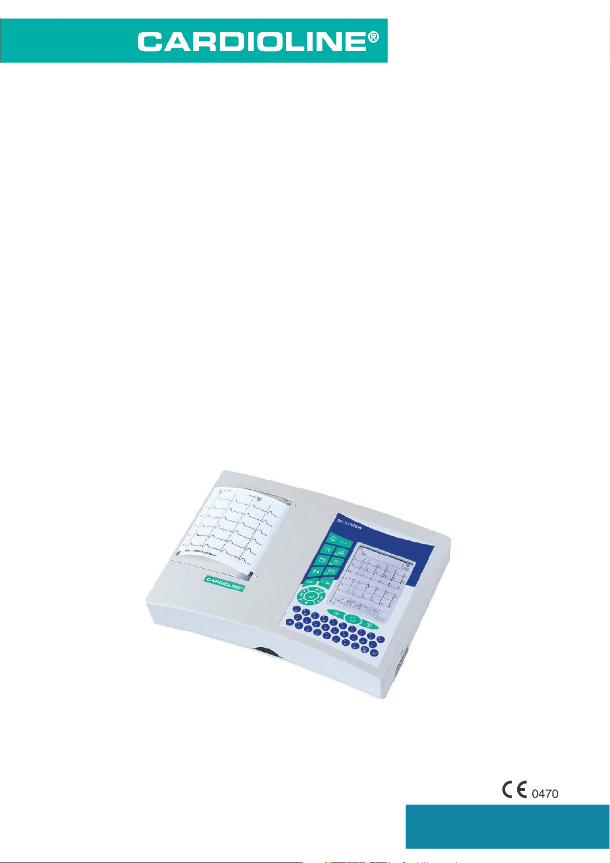
Cardoline AR 1200 VIEW Operating manual

1
AR1200VIEW
CARDIOLINE
®
is an
et medical devices SpA
brand
w w w . c a r d i o l i n e . b i z
T
TE
EC
CH
HN
NI
IC
CA
AL
L
S
SE
ER
RV
VI
IC
CE
E
M
MA
AN
NU
UA
AL
L
E
EL
LE
EC
CT
TR
RO
OC
CA
AR
RD
DI
IO
OG
GR
RA
AP
PH
H
M
MO
OD
DE
EL
L
C
Ca
ar
rd
di
io
ol
li
in
ne
e®
®
A
AR
R
1
12
20
00
0
V
VI
IE
EW
W
P
P/
/N
N:
:
80509531
80509532

2
AR1200VIEW
CARDIOLINE
®
is an
et medical devices SpA
brand
w w w . c a r d i o l i n e . b i z
Index
!
" !
#!
$%$&"'
( !
" (
" ) (
*! +
,- +
* .
!/ .
&! .
" *0)1 .
* 2
34! 2
3-
)
" !
! "
0)14 "
"
( ! "
!! "
" ! "
#!
$
( *&
+ 5 (
+ 1 (
+ 6%*' (
+" $%*' (
+ $!%*' +
+ $-!%*' +
+ $!%*' +
+( $!%*' +
++ $!%*' +
+. $-%*' +

3
AR1200VIEW
CARDIOLINE
®
is an
et medical devices SpA
brand
w w w . c a r d i o l i n e . b i z
+2 %*' .
+ -!%*' .
. ) .
. 1 .
. &7 .
. - 2
." & 2
. 2
. 3 2
. & 2
. 2
2
2 4!
)
)8
)
" )
)-
& "
" !
*
90:;9 +
%0&' +
90:; .
3 .
( $& "

4
AR1200VIEW
CARDIOLINE
®
is an
et medical devices SpA
brand
w w w . c a r d i o l i n e . b i z
1 Introduction
ar1200 view combines reliability, modularity, versatility and capacity to be updated which characterise the latest
generation of cardioline® electrocardiographs.
ar1200 view is a portable electrocardiograph with dual power supply, (mains and rechargeable internal batteries),
which in the basic configuration will:
record an ECG exam in automatic or manual mode;
reproduce the ECG signal on 120 mm paper in 3-6 channel format thanks to the high resolution thermal printer;
storage of the most recent recording in automatic mode and print additional copies.
*In just a few minutes, your ar1200 view can be equipped with:
“memory option”: to store up to 40 full ECG exams, with no need to print out immediately on paper (“paper saving” mode);
"ECG measurements option": automatic ECG parameter measurement program;
"ECG signal interpretive option": a useful and dependable diagnostics support provided by the “HES” program;
"arrhythmia option": program enabling detection of arrhythmia events during continuous recording;
“HRV analysis option”: program enabling detection of variations in heart rate;
"L.E.M.S - PC archive option": to store the exam to archive on a Personal Computer running “L.E.M.S.” (Local ECG
Management System) software;
"R.T.E. - PC-ECG option": for real time display of the twelve leads on your computer screen to allow management of patient
medical records and archiving of exams in digital format using " R.T.E" (Real Time ECG) software. R.T.E has an optional
"HES" module for automatic interpretation of the ECG signal.
* By updating the firmware. Contact your distributor for further details.

5
AR1200VIEW
CARDIOLINE
®
is an
et medical devices SpA
brand
w w w . c a r d i o l i n e . b i z
1.1 Particular recommendations and warnings
This service manual is for the use of competent technical staff only.
Always use the equipment according to the instructions in this manual.
The device is equipped with a set of standard accessories. For reasons of safety, reliability and conformity with the Medical
Devices Directive 93/42/EEC, use only original accessories or accessories approved by the manufacturer.
The device is equipped with a special long-life thermal head writing system, which allows maximum writing precision. To avoid
frequent and costly replacements and repairs, always use the original paper or paper approved by the manufacturer. The
manufacturer will not accept liability for any damage to the device or any other adverse effect caused by the use of unsuitable
paper.
Do not subject the device to impact or excessive vibrations.
Do not allow liquids to penetrate inside the device. If this should accidentally occur, have the device tested by an Authorized
Assistance Centre to verify its functional efficiency, before using it again.
Make sure that the value of the supply voltage corresponds to that indicated on the data plate of the device.
If you are using the device in connection with others, ensure that: all connections are made by skilled persons; all connections
comply with safety regulations; all other devices connected respond likewise to regulations. Non-compliance with these
regulations can cause physical harm to the patient connected and to the person operating the device. Should it be difficult to
obtain the necessary information for assessing the risk of the individual connections, apply directly to the manufacturers
concerned or avoid making the connections.
In the event of other equipment being connected directly or indirectly to the patient, check for the possible risks caused by the
sum of the leakage currents on the body of the patient.
The device is protected against defibrillation discharges in accordance with IEC standard 601-1-25; to ensure that the signal is
restored, use only original electrodes or electrodes responding to IEC and AAMI standards.
If an electrosurgical scalpel is in use, the patient cable should be disconnected from the device.
In any event, the greatest care should be taken when using defibrillators or high-frequency surgical devices at the same time
as the ECG. If you have any doubts while using such devices, disconnect the patient from the electrocardiograph temporarily.
The device recognizes the impulses generated by a pacemaker and does not interfere with its operation, as prescribed by
standards in use at the time of drafting this manual.
Avoid exposing the equipment to extreme temperatures, excessive dust or dirt, and very salty or damp environments; observe
the ambient conditions described in detail under the "Technical specifications” heading.
Periodically check the efficiency of all accessories and of the device itself. Use the built in test function to perform an initial
efficiency check. Contact the Authorized Assistance Centre whenever the device seems to be operating irregularly.
To prolong the life of your ar1200view, have it periodically checked at an Authorised Assistance Centre
Warning: do not use the device in the presence of anaesthetics or volatile gases!
Warning: the indications obtained using automatic interpreting programs or other diagnostic aids must be reviewed and
countersigned by a qualified medical person!
Warning: the device is provided with an IR interface for the transfer of data to other devices. The IR interface must not be
masked , even accidentally, as this will adversely affect its capability and its operation, interrupting and preventing the correct
flow of data.
Warning: Environmental protection: When no longer in use the device must be disposed of according to local regulation, do not
dispose as ordinary refuse.
The manufacturer will acknowledge liability for the safety, reliability and functional efficiency of the device only if:
•modifications and repairs are performed by the manufacturer or by an Authorized Assistance Centre;
•the a.c. mains power supply of the premises in which the device is used corresponds to current regulations;
•the device is operated according to user instructions;
•any accessories in use are those approved by the manufacturer.

6
AR1200VIEW
CARDIOLINE
®
is an
et medical devices SpA
brand
w w w . c a r d i o l i n e . b i z
2 Description of the device
The device consists of the following basic elements:
2.1 Mother board
This is a “Fine line” multilayer printed circuit board for mounting SMD components.
It houses most of the electronic circuits of the device.
2.2 Battery
Battery Pack made of 10 cells NiMH 12V.
2.3 Display
Display assembly is composed of: frame, monochromatic LCD display 320 x 240 pixel (4,7 inch) as well as a step
up converter.
2.4 Keyboard
The keyboard card consists of the device functional keys and LED messaging devices.
2.5 Printer unit
This consists of the thermal printer head support and the mechanical elements required to position it correctly.
2.6 IR Module (RS232)
The function of the IR module is to transmit and receive data from an external PC.
2.7 Motor assembly
The DC motor with gears for paper speed. Also included strobo disk for speed feedback.

7
AR1200VIEW
CARDIOLINE
®
is an
et medical devices SpA
brand
w w w . c a r d i o l i n e . b i z
3 Inputs and outputs
Direct connections from the ar2100 view to external equipment may only be made using the IR serial port, not by
cable.
3.1 Connection to the patient input port
841
2
3
6
75
15 9
10
11
12
1314
Port from connection side
Pin 1 = IN C2 (electrode C2)
Pin 2 = IN C3 (electrode C3)
Pin 3 = IN C4 (electrode C4)
Pin 4 = IN C5 (electrode C5)
Pin 5 = IN C6 (electrode C6)
Pin 6 = AGND (analogue ground)
Pin 7 = NC
Pin 8 = DGND (digital ground)
Pin 9 = IN R (electrode R)
Pin 10 = IN L (electrode L)
Pin 11 = IN F (electrode F)
Pin 12 = IN C1 (electrode C1)
Pin 13 = NC (non connected)
Pin 14 = IN N (electrode N)
Pin 15 = NC (non connected)

8
AR1200VIEW
CARDIOLINE
®
is an
et medical devices SpA
brand
w w w . c a r d i o l i n e . b i z
4 Testing the safety characteristics
The safety regulations envisage two important tests:
The leakage currents test measures the value of the currents lost in relation to the safety of the patient and the operator.
Warning: All safety tests must be performed according to standards EN.60601-1(1990 paragraphs 19 - 20)
EN 60601-2-25 (1995) unless otherwise specified in the local safety regulations.
4.1 Leakage currents test
Warning: This test must be performed every time the device has been opened for inspection and/or
repair, and in any event every two years, unless otherwise specified by the local safety regulations.
Connect the electrocardiogram to the battery charger, and then connect this assembly to the measuring
instrument according to the instrument’s manual, recalling that:
'
The leakage current to the casing is measuring between the mains supply circuits and a metal sheet no greater than 20 x 10 cm
pressed against the casing of the device.
'
The leakage current in the patient is measured between the mains and the applied part. For connection to the applied part use the
patient lead itself.
"'
The leakage current in the patient with mains voltage directly on the applied part (first failure condition) is measured between the meta
sheet connected to the device and the applied part.
'
The auxiliary current in the patient is measured singly on each electrode (excluding the reference electrode) compared to all the other
electrodes connected together.
Note: Make the measurements following the indications in the instrument user manual, and check that the leakage current values
measured are less than or equal to those listed in table IV.
Table IV.
Admissible permanent values for leakage and auxiliary currents in the patient in mA (milliamperes).
:) &3)
,- 2
,- 2 2
,-< 22 22
,-
%'
77777 22
9=!< 22 22
:)>:
&3)>3

9
AR1200VIEW
CARDIOLINE
®
is an
et medical devices SpA
brand
w w w . c a r d i o l i n e . b i z
5 Testing the main technical
characteristics of the ecg
Warning: All tests must be performed in compliance with the provisions of the related general, detailed
and performance safety regulations listed in the technical characteristics section
5.1 Instruments necessary:
a) sample mV generator with the following characteristics:
b) low frequency sine wave generator;
c) ECG simulator.
5.2 Sensitivity test
set the device up to record 6 channels on leads V1 to V6 with sensitivity of 20 mm/mV;
connect the patient cable to the device;
connect terminals C1 C6 of the patient cable connected to the device to the positive pin of instrument 5.1.a);connect all the
other cable terminals to the negative pin of instrument 5.1 a);
record the signal for a few seconds;
check that the amplitude of the recorded signal is 20mm. +/- 5% on all channels.
5.3 Testing the ECG leads
switch the device on;
connect the patient cable to the device;
connect the red termination of the patient cable to the positive pin of the instrument specified in point 5.a.a and the remaining
wires to the negative pin.
start recording and check that the amplitude in mm of the signal, and its polarity (positive or negative) comply with the values
indicated in table 5.3.
repeat the measurements in sequence with the remaining active terminations G - V - C1 - C2 - C3 - C4 - C5 - C6 of the patient
cable using the method described in c), and check that the values correspond to those indicated in table 5.3.

10
AR1200VIEW
CARDIOLINE
®
is an
et medical devices SpA
brand
w w w . c a r d i o l i n e . b i z
!" #$"%$%
&"" !&"& '
!" (" !" #$&"" !&"
) :*-
?①
:*
7②③④⑤⑥⑦⑧⑨⑩
:.*2
&4/ 0/@A2
5B±C @±"C ±C
#$&)$(
*
$%"%)$(&!($
+
!, !!, !!!, ) )$ ) ) ) )- ). )/ )
+0
** ** ** ** ** ** ** ** ** ** ** **
$ 72 72 2 ?2 7 7 7"" 7"" 7"" 7"" 7"" 7""
1 ?2 2 72 7 ?2 7 7"" 7"" 7"" 7"" 7"" 7""
@ 2 ?2 ?2 7 7 ?2 7"" 7"" 7"" 7"" 7"" 7""
) 2 2 2 2 2 2 ?2 2 2 2 2 2
) 2 2 2 2 2 2 2 ?2 2 2 2 2
)" 2 2 2 2 2 2 2 2 ?2 2 2 2
) 2 2 2 2 2 2 2 2 2 ?2 2 2
) 2 2 2 2 2 2 2 2 2 2 ?2 2
) 2 2 2 2 2 2 2 2 2 2 2 ?2
1/-
5.4 Testing the paper feed rate
switch on the device and connect the patient cable;
connect terminals C1 C6 of the patient cable to the positive pin of instrument 5.1.a);
connect all the other cable terminals to the negative pin of instrument 5.1 a);
using the instrument with a square wave of 1 Hz and an amplitude of 1 mVpp;
record the signal on leads V1 V6;
measure the length of the wave cycle recorded on the paper.
The results should be as follows:
Period = 50 mm +/- 5% for a feed rate of 50 mm/s;
Period = 25 mm +/- 5% for a feed rate of 25 mm/s;
Period = 5 mm +/-10% for a feed rate of 5 mm/s;
5.5 Frequency response test
switch on the device and connect the patient cable;
connect terminals C1 C6 of the patient cable to the positive pin of instrument 5.1.a);
connect all the other cable terminals to the negative pin of instrument 5.1 a);
set the sine wave generator to 10Hz with an amplitude of c. 1mVpp;
select leads V1 V6 and a sensitivity of 10 mm/mV.;
make a recording and adjust the amplitude of the generator so as to obtain a 10 mm excursion of the signal recorded;
vary the generator frequency from 0.5Hz to 100Hz with constant amplitude;
check that the frequency response is in accordance with the values in table 5.5.

11
AR1200VIEW
CARDIOLINE
®
is an
et medical devices SpA
brand
w w w . c a r d i o l i n e . b i z
*+203
*)
(200+
03'4
++2
03
'4**
32(2 ±2C
3222 ?2C7"2C
28 3222 ?2C7"2C
*
Note: The 0.5 Hz pitch linear phase anti-drift filter is always on and cannot be switched off.
The 50 or 60 Hz filter eliminates modified notch digital type mains disturbances in the linear phase, with a frequency
response of 32 Hz - 3dB.

12
AR1200VIEW
CARDIOLINE
®
is an
et medical devices SpA
brand
w w w . c a r d i o l i n e . b i z
6 Functional blocks
6.1 Mother board
The motherboard is based on the following principal components:
6.1.1 Processor
32 bit Fujitsu MB91101 RISC microprocessor with 12 MHz clock
2 x 4 Mb static rams
2 x 8 Mb flash memories including the following software:
•boot code;
•operating system software;
•applications software;
•calibration data;
•ECG archive.
Execution of static ram self test.
6.1.2 Connection to mains
The equipment must be connected to a mains voltage 115 V~ or 230 V~ ± 10%, 50- 60 Hz .
The mains voltage switch is located under the label (see table T1, rif. 5-6).
Changing mains voltage imply the replacement of the mentioned label. Only original ones can be used to
assure proper electrical isolation.
In order to change mains voltage move the 3 jumper as illustrated in the picture below.
Changing mains voltage does not require mains fuses rate modification.
#++*5
Warning: Changing mains voltage imply the replacement of the mentioned label. Only original ones can
be used to assure proper electrical isolation.
In order to change mains voltage move the 3 jumper as illustrated in the picture below.
The Manufacturer declines all responsibility for any damage caused as a result of tampering.
6.1.3 Battery charger
The battery charger section consists of the following parts:
Adapter circuit, 230/115Vac, switched trough jumper on the equipment bottom, out 22 Vac, fuse protected, and PTC protection
against overheating.
Mains filter against electromagnetic disturbances.
Rectification, voltage stabilisation and current limitation circuits.
Testing the battery charger circuit (see sheet 2 el diag)
If the mains on led does not light up, check using the following procedure:
Disconnect the mains cable;
Check the externally accessible mains fuses;
Disconnect the battery from the device as indicated in chapter 8.4;

13
AR1200VIEW
CARDIOLINE
®
is an
et medical devices SpA
brand
w w w . c a r d i o l i n e . b i z
Connect a amperometer to the free terminal caps;
Connect the mains cable: the reading should indicate a current of 150 mA ± 15;
If the reading is outside the range of values indicated, replace the motherboard.
6.1.4 Internal circuit power supply
This consists of the following power supplies:
+5 V generated by a switching type voltage regulator;
5 VI – VL to supply the patient input analogue circuits on the hybrid circuit (insulated part);
+ 3.3 V generated by a linear regulator to supply the control logic;
+ 3 V reference voltage for the A/D converter;
VTPH voltage obtained from the battery to supply the thermal head. This voltage is limited to a current of 5A and stabilised in
voltage at +25 Vdc enabled only when printing.
Testing internal circuit power supplies (ref sheet 2 el diag)
Check fuse F1 (T 5A);
If no power is supplied to the internal circuits, replace the motherboard.
6.1.5 ECG acquisition
This consists of the following parts:
Patient input connector;
Protection against defibrillator discharges;
Signal polarisation circuit;
Hybrid circuit for amplification, filter and clamp.
6.1.6 Motor control
This consists of the following parts:
Stroboscopic sensor control;
Phase comparator between reference frequency and motor feedback;
Current amplifier for motor power supply.
6.1.7 Display control
This consists of the following parts:
Display controller S1D13704 EPSON;
Buffer adapter level from 3,3V to 5V;
Step up converter for LCD power supply.
6.2 Display assembly
This consists of the following parts:
Graphic LCD monochromatic 320 x 240 pixel (4,7 inch), effective area 100x75 mm;
Step up converter for back lit lamp power supply
Testing the display
Execution of display self-test;
6.3 Battery
NiMH battery 12V-1800 mAh
The battery is protected against short circuits by a Polyswitch 3,5A.
Complete recharging requires at least 18 hours or longer. The battery can be partially recharged, in this case to prolong the life
of the battery it should be fully discharged and recharged every 2 months.
Replace the battery with one of equivalent type, voltage and capacity.
Attention: In order to ensure a correct equipment operation and safety, replace the battery with original et
medical devices battery pack.
Warning: The battery must only be removed if the device is off and the mains supply cable disconnected.

14
AR1200VIEW
CARDIOLINE
®
is an
et medical devices SpA
brand
w w w . c a r d i o l i n e . b i z
Do not dispose of a spent battery as ordinary refuse or litter.
Note: The operation of the device is not guaranteed if the battery is flat or missing.
Note: The configuration parameters and any stored ECGs are not lost when the battery is changed.
Note: Update the system date and time after replacing the battery.
Battery check
Proceed as follows to check the efficiency of the battery:
Leave the battery on charge for at least 18 hours;
Disconnect the mains cable;
Activate printing of an ECG in manual mode on 3 channels at 5 mm/s: if the device shows the battery is flat within the first 5
minutes the battery should be replaced.
6.4 Keyboard card
The keyboard consists of:
18 function keys;
10 alphanumeric keys;
1 LED for mains line indication;
CPU connection through bi-directional synchronous serial port.
Testing the keyboard card circuits
Execution of keyboard self-test;
6.5 Printer unit
This consists of the thermal printer head support and the mechanical elements required to position it correctly.
864 dot high resolution printer head, 8 dots per mm;
support;
paper feed unit consisting of 1 direct current reduction gears, equipped with stroboscopic speed control;
mark detection sensor.
Testing the print unit
Execution of printer self-test.
6.6 IR Module
The function of the IR module is to transmit and receive data from an external PC. The IR module can be used to perform the
following functions:
Updating firmware (Loader)*;
Batch ECG transmission (L.E.M.S.)*;
Real time ECG transmission (R.T.E ir)*.
*Consult the specific manual for further information.

15
AR1200VIEW
CARDIOLINE
®
is an
et medical devices SpA
brand
w w w . c a r d i o l i n e . b i z

16
AR1200VIEW
CARDIOLINE
®
is an
et medical devices SpA
brand
w w w . c a r d i o l i n e . b i z
7 Trouble Shooting
Defect Possible cause/symptom Remedy
The device does not switch on in any
mode. Mother board/keyboard card. Holding down the ON/OFF key,
measure 12Vdc on J52 (keyboard
connector) pin 3; if absent replace the
keyboard card, if not, replace the
motherboard.
The device does not switch on when
in mains mode.
Mains LED indicator off. Check mains fuses, if OK replace
motherboard.
The device does not switch on when
in battery mode.
Check T5A fuse on motherboard.
Check efficiency of battery and
replace if necessary.
The battery does not charge. The device has not been charged for
long enough.
Mains LED indicator off.
Defective battery.
Leave the device charging for at least
24 hours.
Check mains fuses, if OK replace
motherboard.
Check efficiency of battery and
replace if necessary.
Check T5A fuse on motherboard.
Keyboard keys not working.. The key pressed not enabled for the
specific function.
Execute keyboard self test and if it
fails replace keyboard card.
The paper feeds through without
printing.
Paper not suitable, without black page
recognition mark.
Check that original paper is being
used.
Check the paper has been inserted
correctly.
Check that the 26 Vdc VTPH power
supply to the thermal print head is
present when printing is active, if not,
replace the mother board.
Check signals on test point table T8
are present. If good, replace thermal
head unit, otherwise replace
motherboard.
Anomalous printout. Clean thermal head.
Execute printer self-test, replace
thermal head unit if some dots are
missing.
Does not print automatically or does
not paginate the trace correctly. Paper not suitable, without black page
recognition mark. Clean mark sensor
Perform mark sensor calibration.

17
AR1200VIEW
CARDIOLINE
®
is an
et medical devices SpA
brand
w w w . c a r d i o l i n e . b i z
Defect Possible cause/symptom Remedy
Replace print unit.
Paper feed defective, or paper
finished message with paper present. Check paper guides are not damaged.
Clean rubber roller
Replace print unit.
EC signal disturbed or anomalous.
Error message on display, on printout.
See user manual.
The device stops during use.
No functions operational, no
commands accepted. Press reset button on right side of
device.
Blank display.
Backlit lamp blown or step up
converter failed
Check for brightness regulation
Replace display assembly
No data on display.
Check for contrast regulation
Perform display self test
Verify proper flat connection between
mother board and display assembly
Verify on display connector J49
presence of LCD data signal (level
from 0 trough 5 V), if present replace
display assembly otherwise replace
mother board
8 How to dismantle and reassemble the
device
8.1 General precautions
Disconnect the mains cable before opening the unit.
See chapter 15 (procedures for handling ESD components).
To reassemble the device, perform the operations described below in reverse order, ensuring that all
subassemblies and connections are performed correctly.
8.2 Opening and closing the device (table T1)
Remove battery pack as per § 8.4;
Remove the 6 fixing screws from the mobile base (T1 Ref. 1);
Lift the mobile base of the device;
Remove the lower mobile part;
To reassemble the equipment proceed in reverse order.
8.3 Removing the mother board (table T2b)
Proceed following the instructions in chapter 8.2;
Remove 2 screws (T2b Ref. 1);
Lift the patient connector side of the board and disconnect the following:

18
AR1200VIEW
CARDIOLINE
®
is an
et medical devices SpA
brand
w w w . c a r d i o l i n e . b i z
•keyboard flat;
•thermal head flat;
•motor flat;
•mark sensor card flat;
•display connector flat;
•inverter flat.
To reassemble the motherboard proceed in reverse order.
Warning: Replacing the motherboard means that the paper feed speed and mark presence sensor must
be recalibrated.
8.4 Removing the battery (table T1)
Proceed as follows:
lay the equipment on a soft work surface with the bottom of the casing facing upwards;
remove the door of the battery compartment after having slackened its retaining screw (table T1 Ref. 2);
disconnect and remove the set of batteries (table T1 ref.8,9);
To reassembly, proceed in inverse order.
Warning: Respect the correct polarity of the battery connection as specified in Table T1 ref.7,8.
8.5 Removing the keyboard card (table T2b)
Proceed as described in chapter 8.3;
Remove 5 screws (T2b Ref. 5); replace the keyboard card.
To reassembly, proceed in inverse order.
8.6 Removing the display (table T2b)
Proceed following the instructions in chapter 8.2;
Remove the 5 screws attaching the display to the housing (T2b Ref. 2);
Remove display.
8.7 Removing the motor assembly (table T2b)
Proceed as described in chapter 8.3.;
Remove 2 screws (T2b Ref. 4) and remove the motor assembly;
To reassembly, proceed in inverse order.
8.8 Removing the printer assembly (table T2b)
Proceed as follows:
proceed as in chapter 8.3 for opening the equipment and removing the mother board from the equipment;
remove the 2 retaining screws of the printer assembly, see table T2b Ref.3, remove it from its seat, taking care not to damage
the dots of the thermal head with hard objects;
proceed in inverse order to fit the printer assembly, paying particular attention to the positioning of the mechanical part with
screws, washers, etc.; if the printer assembly is equipped with thermal print head regulation see table T4.
to obtain long life of the thermal head, using exclusively the heat-sensitive paper recommended by the manufacturer, DOT-
CARDin rolls and packs with height 120 mm is advised. The order code is marked on the bottom edge of the paper;
the thermal head is extremely sensitive to electrostatic potentials, it is recommended always to follow the work procedures
described in appendix A.
8.9 Removing mark sensor board (table T2a)
Proceed as follows:
proceed as in chapter 8.3 for opening the equipment and removing the mother board;
to remove the sensor board, force it upwards using a suitable tool. It is glued into its compartment inside the upper casing, see
table T2a Ref. 2;
to replace the board it is necessary to clean the area in which it is fitted, position it correctly in its compartment, with the output
of the flat towards the paper compartment and stick it down with instant glue;

19
AR1200VIEW
CARDIOLINE
®
is an
et medical devices SpA
brand
w w w . c a r d i o l i n e . b i z
to close the equipment perform the operations in inverse order;
the replacement of the sensor card requires its calibration, see chapter 8.
8.10 Dismantling the paper feed (table T1)
The paper compartment door system is a mechanical device, inserted in the casing, accessible from the outside,
driven by the motor of the equipment, which transports the heat-sensitive paper.
It is located above the paper compartment and covers it completely.
To remove this part, proceed as follows:
Insert a tool in the special hollow in the left-hand wall of the equipment where the paper comes out and exert pressure upwards
so as to release the paper compartment door.
This assembly must be disassembled before inserting a roll or pack of paper, when cleaning the roller and always before
opening the equipment.
To reassembly it, slip it into place with the rubber roller towards the inside of the equipment and holding it up on the other side.
As soon as it is inserted, press gently down, on the raised side, so as to snap it shut.
Note: If the roller is not clean and the paper compartment door is badly inserted or fastened, the paper
transport is faulty and the equipment functions incorrectly.
8.11 Dismantling and replacing the keyboard membrane (table T1)
The keyboard plate is an elastic membrane fitted on top of the keyboard to allow its control buttons to be pressed.
This self-adhesive plate is stuck onto the top of the equipment.
To replace it when worn, lift one corner using a fine blade and pull it off the casing.
If any adhesive is left on the casing, you must remove it by rubbing with your fingertips.
To fit a new plate, center it with the corners in the space provided and press gently over the whole surface.
Note: A broken or cracked keyboard membrane compromises the safety of the device.
9 Calibration and setting
9.1 General information
This device has a system to automatically set the paper feed speed and mark detection sensor.
The device does not require further setting.
The calibration system may be accessed from the service menu as described below.
9.1.1 Self-test
The device is pre-set to execute self-testing of the main functions: the access sequences for the various menus
are guided on the display.
Two types of self-testing may be performed: USER (1) and SERVICE (2), according to the tests to be executed.
USER
To enter the self-testing menu, switch on the device, press the MENU key and select and confirm the TOOLS,
SELF-TEST, USER(1) submenu using the arrow key (DOWN). The following tests are available in the operator
section:
Display: pixel scan. The presence of blank areas signifies faulty operation of the display.
Keyboard: the position of the single keys is simulated in the display. Pressing a given key, the corresponding area of the
display is highlighted in reverse. A lack of response in any one area indicates that the relative key is faulty.
Printer: the system prints two triangular waves, the character set in the memory, and signals with different speeds and
sensitivities. Irregularities in the printing system are indicated by the presence of non-continuous lines (burnt dots).
Memory: a non-destructive test is performed on the memories (the data in the memory are not cancelled), and a report of the
following type is then printed (all tests OK).

20
AR1200VIEW
CARDIOLINE
®
is an
et medical devices SpA
brand
w w w . c a r d i o l i n e . b i z
<<< ar1200 view MEMORY TEST >>>
Boot : CRC OK
Application : CRC OK
Language : CRC OK
Ram Memory : OK
Info: The following items of information are printed: model identification, serial number of the device, details of software
installed, version and language code, reference of any options installed.
SERVICE
To enter the self-testing menu, switch on the device, press the MENU key and select and confirm the TOOLS,
SELF-TEST, SERVICE(2) submenu using the arrow key (DOWN). When the access code is requested, press the
following keys: FILTER – AMPLITUDES – SPEED – START and confirm.
the following tests are available in the service section:
9.1.2 Mark calibration
Confirm the submenu MARK CALIBRATION (1), position the mark at a distance from the sensor (visible near the
exit from the device), and confirm “enter”
The microprocessor automatically reads the sensor output voltages, voltage with white paper and black mark, and
then sets the digital trimmer that regulates the photodiode current to the optimal settings and then stores them.
The mark calibration voltages are shown on the display, as is the numerical position of the digital potentiometer.
9.1.3 Speed calibration
Testing and setting
Select and firm the SPEED CAL. (2) submenus, and the speed to calibrate
The following messages then appear on the display: Output PWM0 Output – Freq = xxxx Hz with the possibility
of selecting from: test – change – exit.
Confirming the “test” command enables the paper feed and the print unit emits a 1 impulse per second signal. If
the speed has to be calibrated, select “change” and increase or decrease the frequency to set the paper feed
speed entered. When the speed has been set correctly, select and confirm with “exit”.
The permitted tolerance values for the various paper feed speeds are as follows:
50 mm/s ± -5%
25 mm/s ± -5%
5 mm/s ± -10%
9.1.4 Metres of paper printed
Displays the number of metres of paper printed.
9.1.5 Firmware upgrades
Enables upgrading of the instrument’s internal firmware.
The firmware upgrade menu can be accessed from the main menu, pressing the Shift + S keys together.
Note: Refer to the “Loader” programme manual for further information.
9.1.6 Print Screen
Enable print screen ( for internal use only)
It is highly recommended to leave this function disabled.
9.2 Print head alignment
In case of print head adjustment remove mother board as per § 8.3, then follow instructions provided in table T4,
repeat adjustment until the best result is obtained.
This manual suits for next models
2
Table of contents