Carel VRDXL00001 User manual

USER MANUAL
VRDXL00001
Steam blower
ENG
LANTAVENT.RU | отдел продаж: [email protected]
Оборудование Carel: автоматика, увлажнители, комплектующие

ENG
Index
1. INTRODUCTION 7
1.1 Description 7
2. PREPARING FOR ASSEMBLY 10
2.1 Requirements 10
3. ASSEMBLY 12
3.1 Preliminary operations 12
3.2 Assembly 12
4. MAINTENANCE AND SPARE PARTS 14
4.1 Components 14
4.2 Component replacement 14
5. TECHNICAL SPECIFICATIONS 16
VRDXL00001 +030222195 rel. 1.4 - 11.02.2021 |5
LANTAVENT.RU | отдел продаж: [email protected]
Оборудование Carel: автоматика, увлажнители, комплектующие

1. Introduction
1.1
Description
The blower for CAREL heaterSteam, humiSteam, gaSteam isothermal humidifiers distributes steam
directly into rooms in structures that do not feature an air distribution system. The appliance must be
wall-mounted.
1.1.1 Models
P/N Power supply Maximum steam flow-rate (kg/h)
VVRDXL00001 230 Vac (mains) 45
Tab.1.a
1.1.2 Material supplied
Description Qty
Y connection pipe for steam input 1
Steam hose (L = 350 mm/13.8 in, Ø 30 mm/1.2 in) 2
Metal clamp for steam hose 4
Cable gland + anchor kit 1
Tab.1.b
Note: the "Y" connection pipe has input with ID 40mm (1.57in) and 2 outputs with ID 30 mm (1.18in).
1.1.3 Accessories
P/N Description
1312368AXX Condensate hose (ID = 9 mm/0.35 in)
1312365AXX Steam hose (ID = 30 mm/1.18 in)
1312367AXX Steam hose (ID = 40 mm/1.57 in)
Tab.1.c
1.1.4 Receiving/identification
After having received the appliance, check that the box is not damaged and all of the components have
been delivered. Verify on the identification rating plate that the model is suitable for the required
installation.
Note: immediately report any damage to the carrier.
Store the appliance in a protected area in the conditions specified in the technical data table.
The appliance can be identified via the rating plate on the rear, which shows the part number, model,
serial number and other information.
Fig.1.a
ENG
VRDXL00001 +030222195 rel. 1.4 - 11.02.2021 1. Introduction|7
LANTAVENT.RU | отдел продаж: [email protected]
Оборудование Carel: автоматика, увлажнители, комплектующие

ENG
1.1.5 Dimensions - mm (in)
Fig.1.b
1.1.6 Structure
Fig.1.c
Ref. Description
1 Steam outlet
2 Air outlet
3 Light
4 Fans
5 Thermostat (klixon)
Ref. Description
6 Terminal block
7 Fuse holder
8 Condensate outlet fitting (Ø 9 mm - 0.35 in)
9 Steam hose fitting (2 X Ø 30 mm (1.18 in))
1.1.7 Operating principle
The blower is connected to the power supply. When steam enters the blower, after a certain time either
the thermostat detects a temperature of 50°C or the output (terminal J19) on the c.pHC controller gives
the signal and the fans are activated. The air, taken in from the rear, is mixed with steam before being
delivered into the room, where it is easily absorbed. The blower features two different types of
operating logic:
1. independent of the humidifier;
2. managed directly by the humidifier (c.pHC). The controller delays blower activation for a set time.
Deactivation can also be delayed to allow the blower to dry.
Note: the 230 Vac power supply to the steam blower is supplied externally by a dedicated line. If the
humidifier has to manage the steam blower (with c.pHC controller), use the J19 contact as in the
following drawing.
8|1. Introduction VRDXL00001 +030222195 rel. 1.4 - 11.02.2021
LANTAVENT.RU | отдел продаж: [email protected]
Оборудование Carel: автоматика, увлажнители, комплектующие

1.1.8 Wiring diagram
Fig.1.d
Key
FU Fuse
T Thermostat (klixon)
FANS Fans
L Light
Note: use the previous drawing to supply in parallel up to 3 steam blowers. With 4 steam blowers,
use an external relay (not supplied), managed by a 24 Vac command from the c.pHC controller. The
230 Vac power supply to the 4 steam blowers remains external.
Removing the jumper
Notes:
lif the humidifier is not fitted with the c.pHC controller, remove the jumper. The blower will be
activated by the built-in thermostat;
lfor the list of humidifiers where the jumper must be removed, see the following table.
Unscrew the screws to remove the jumper P.
Fig.1.e
The blower leaves the factory with the jumper inserted (= blower managed by the c.pHC controller on
the humidifier).
HUMIDIFIERS ON WHICH THE JUMPER MUST BE REMOVED
Part number Humidifier model
UR*******1/2 UR up to revision 2
UE*******1 UE up to revision 1
UG*******1/2/3 UG up to revision 3
ENG
VRDXL00001 +030222195 rel. 1.4 - 11.02.2021 1. Introduction|9
LANTAVENT.RU | отдел продаж: [email protected]
Оборудование Carel: автоматика, увлажнители, комплектующие

ENG
2. Preparing for assembly
The blower must be mounted or on the wall and connected to the humidifier via the steam hose.
The maximum length of the steam hose is 4 m.
Note: observe the minimum distances shown in the following figures to prevent the flow of
humidified air from coming into contact with people, electrical equipment, false-ceilings and cold
surfaces before the steam is totally absorbed by the atmosphere.
Fig.2.a
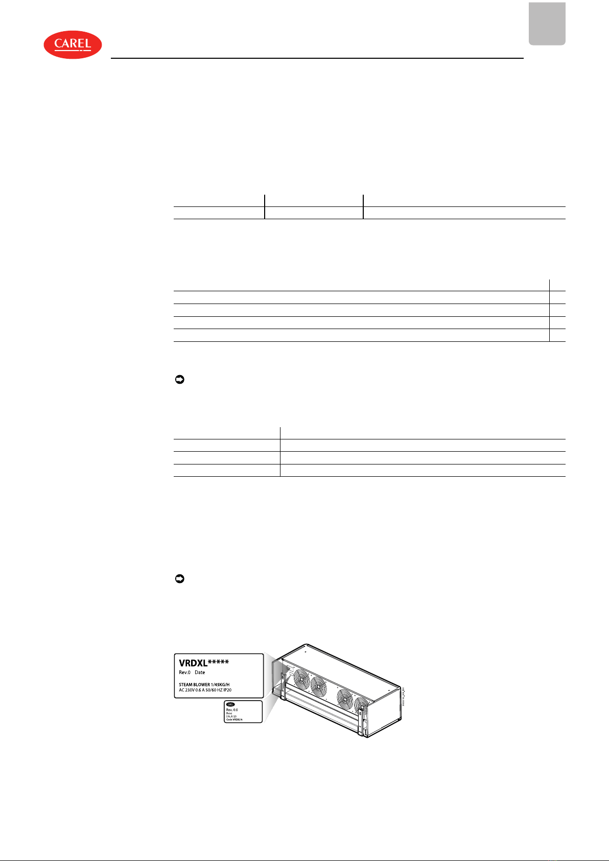
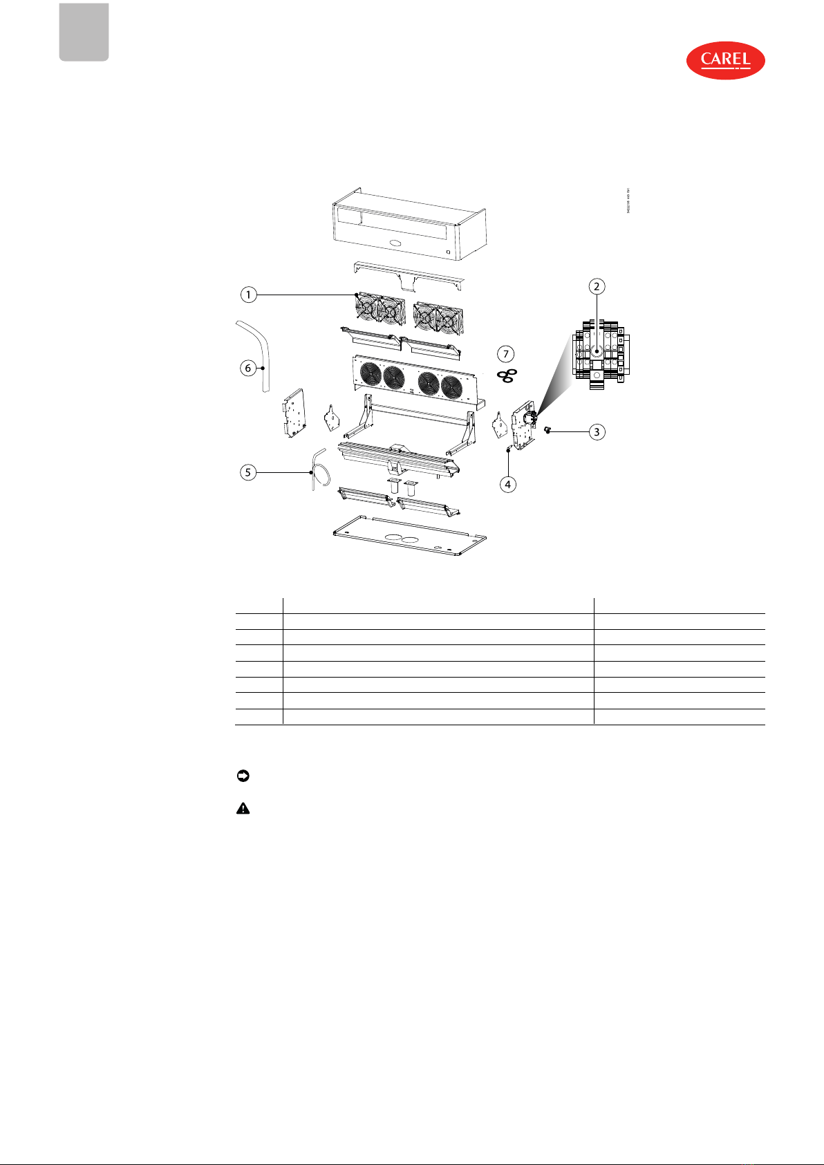
Mounting (all dimensions in m[ft])
Ref. Wall
A >5[16.4]
B ≥2[6.5]
C + E ≥ 2.1[6.8]
D >0.5[1.6]
E ≤4[13.1]
Tab.2.a
Notes:
ldimension C+E can be lower if it is not possible to transit in front of the blower unit;
lsee the humidifier manual for details on positioning.
2.1
Requirements
2.1.1 Steam hose
Follow these instructions when installing the steam hose:
lonly use hoses supplied by CAREL; hoses made from other materials may adversely affect operation of
the system;
lthe steam hose must be secured by supports (clamps, brackets) so that it does not bend and does not
weigh on the humidifier. A hot hose is more likely to bend;
lthe minimum radius of curvature of the steam hose is 5 times the inside diameter;
lthe steam hose must have a minimum slope in order to drain condensate back to the humidifier; in
any case, always install a condensate drain at the lowest point on the steam hose;
lminimise the length of the steam hose so as to reduce heat loss. Avoid the formation of pockets or
traps where condensate may accumulate;
lchoking (due to bends or twisting of the hose) can cause excessive back-pressure in the humidifier
cylinder when the unit is operating and consequently sudden steam outlet.
Important:
ldo not install a stop valve in the steam hose;
lwhen installation is complete, flush the steam line to remove any contaminants and processing
10|2. Preparing for assembly VRDXL00001 +030222195 rel. 1.4 - 11.02.2021
LANTAVENT.RU | отдел продаж: [email protected]
Оборудование Carel: автоматика, увлажнители, комплектующие

residues.
lexposure of the skin to a jet of hot steam may cause severe burns;
ldo not over-tighten the hose clamps (max. torque=180 N·cm).
2.1.2 Condensate hose
Follow these instructions when installing the condensate hose:
lthe condensate hose may be filled with hot water or steam: contact with the skin can cause serious
burns;
lconnect the hose to a drain in accordance with national and local regulations in force;
lthe condensate hose must have a minimum downward slope and must flow into a 200 mm high drain
trap: the drain trap must be at least 300 mm below the connection to the blower.
lcondensate drains must be installed at all the lowest points and wherever the drain line goes from
horizontal to vertical. The drain line must be connected to a “T” connector and have a minimum
downward slope. The drain trap must be at least 300 mm below the connection.
lmake sure that the condensate drain lines are not blocked;
ldo not over-tighten the clamps on the condensate hose.
Important: before starting the humidifier, fill the drain traps with water.
Fig.2.b
ENG
VRDXL00001 +030222195 rel. 1.4 - 11.02.2021 2. Preparing for assembly|11
LANTAVENT.RU | отдел продаж: [email protected]
Оборудование Carel: автоматика, увлажнители, комплектующие

ENG
3. Assembly
3.1
Preliminary
operations
3.1.1 Removing the cover
For steam blower installation or maintenance, remove the cover from the appliance as described below:
1. Disconnect the blower from the power supply;
2. Unscrew the two fixing screws placed on the top of the cover;
3. Pull the cover up by slightly turning it forward to release it.
Fig.3.a
3.2
Assembly
3.2.1 Wall-mounting
Important: mount the blower only on masonry walls.
Fixing the blower to the support
Procedure:
Fig.3.b
Fig.3.c
1. Remove the cover (see previous paragraph). Unscrew
the screws (A) and remove the bottom panel (B).
2. Remove the screws and extract the support from the
blower.
Fig.3.d Fig.3.e
3. Make the holes in the wall to fix the support. 4. Use a spirit level for mounting
12|3. Assembly VRDXL00001 +030222195 rel. 1.4 - 11.02.2021
LANTAVENT.RU | отдел продаж: [email protected]
Оборудование Carel: автоматика, увлажнители, комплектующие

Fig.3.f
5. Fix the blower to the support and then mount the bottom panel (A), tighten the metal clamps to fix the steam hoses
(B) and then condensate hose. Connect the power supply cable to the terminal block. At the end mount the cover (C)
again.
Note: install the steam hose, the condensate hose and the power cable following the steps described
in the previous paragraph and the notes in chap. "Preparing for assembly".
ENG
VRDXL00001 +030222195 rel. 1.4 - 11.02.2021 3. Assembly|13
LANTAVENT.RU | отдел продаж: [email protected]
Оборудование Carel: автоматика, увлажнители, комплектующие

ENG
4. Maintenance and spare parts
4.1
Components
Fig.4.a
No. Description Spare part no.
1 Fan 230 V VRDXLFAN01
2 Fuse 800 mA T VRDXLFUS01
3 Thermostat (klixon) VSDCLX0003
4 Light 230 Vac VRDXLLUX01
5 Condensate hose 1312368AXX
6 Steam hose (Ø 40 mm/1.57 in) 1312367AXX
7 Gasket kit VSDGUAR000
Tab.4.a
4.2 Component
replacement
Note: Maintenance on the humidifier must be carried out by CAREL Technical Service or professionally
qualified personnel.
Important: before proceeding:
ldisconnect power to the humidifier by turning the main system switch to OFF;
lremove the cover from the blower (see the previous paragraph);
lreplace the faulty component;
lonce having completed maintenance, reassemble the components by working in reverse to the
steps described above.
4.2.1 Fan
After having removed the blower cover (see chap. “Assembly”):
A. remove the screws that secure the rear panel with the slits;
B. unplug the electrical connectors;
C. unscrew and remove the screws to replace the fan (paying attention to the rear grilles).
D. reassemble everything following the opposite process.
14|4. Maintenance and spare parts VRDXL00001 +030222195 rel. 1.4 - 11.02.2021
LANTAVENT.RU | отдел продаж: [email protected]
Оборудование Carel: автоматика, увлажнители, комплектующие

Fig.4.b
4.2.2 Light/thermostat/fuse
After having removed the blower cover (see the previous paragraph), for replacement proceed as follows:
llight (A): press the tabs at the side to remove it, disconnect the wires from the terminal block;
lthermostat (B): disconnect the electrical connectors and unscrew the fixing nuts using a socket wrench;
lfuse: unscrew the fuse holder (C).
Fig.4.c
4.2.3 Troubleshooting
Problem Cause Solution
The fan is not working
lThe fan is only activated when the
humidifier generates steam
lThe blower is not powered
lFaulty fan
lCheck power supply
lCheck fuse
lMake sure that the humidifier is
operating and humidity production is
required
The fan is not working but the
humidifier is generating steam
lSteam line installed incorrectly, not
enough steam reaches the blower
lThermostat stuck
lThe blower is not powered
lFaulty fuse
lMake sure that the steam hose is not
bent
lDrain trap installed correctly and not
blocked
lVerify that when the thermostat is closed
there is electrical continuity
lCheck the humidifier connection cable
Blower sprays droplets of
condensate
lBlower not mounted perfectly
horizontally
lRear air intake blocked
lCheck
Tab.4.b
ENG
VRDXL00001 +030222195 rel. 1.4 - 11.02.2021 4. Maintenance and spare parts|15
LANTAVENT.RU | отдел продаж: [email protected]
Оборудование Carel: автоматика, увлажнители, комплектующие

ENG
5. Technical specifications
Description Value or range
Power supply (V~) 230 Vac (+ 5%, -10%), 50/60 Hz
Steam inlet ϕ(mm) (2 x) 30
Condensate drain ϕ(mm) 9
Maximum steam flow-rate (kg/h) 45
Ingress protection IP20
Storage temperature/humidity (°C) -10.... +70°C / 10...80 rH% non-condensing
Nominal power (W) 120
Nominal air flow rate (m3/h) 576
Sound level (open field at maximum speed and a distance
of 1 m) (dB) 50
Operating temperature/humidity (°C/rH%) 1... 50°C / 10...80 rH% non-condensing
Dimensions (mm/in) 687 x 278 x 194 (27.0 x 10.9 x 7.6)
Weight (kg) 9.5
CE conformity: Directives: 2014/35/EU, 2014/30/EU
IEC 60335-1, Edition 5.2 dated 2016-05
IEC 60335-2 98: 2002 (Second edition) + A1: 2004+A2: 2008
IEC 60335-1 2010 (Fifth edition) incl. Corr 1: 2010 and Corr2:
2011+ A1: 2013
UL conformity: UL 998/CSA C22.2 No 104-R1999
5.0.1 Humidifier connection tables
humiSteam
humidifier outlet ø mm ---> 22 /30 (0.9")/(1.2”) 30 (1.2”) 40 (1.6”) 2x 40 (1.6”) 4x 40 (4x 1.6”)
humidifier capacity kg/h ---> 1 3 5 8 9 10 15 18 25 35 45 65 90 130
humidifier ---> UE001 UE003 UE005 UE008 UE009 UE010 UE015 UE018 UE025 UE035 UE045 UE065 UE090 UE130
VSDU0A0003 (≤18kg/h) 1 1 1 1 1 1 1 1
VRDXL00001 (≤45kg/h) 1 1 1 2 2 4
Tab.5.a
heaterSteam
humidifier outlet ø mm ---> 30 (1.2”) 40 (1.6”) 2x 40 (1.6”)
humidifier capacity kg/h ---> 2 4 6 10 13 20 27 40 53 60 80
humidifier ---> UR002 UR004 UR006 UR010 UR013 UR020 UR027 UR040 UR053 UR060 UR080
VSDU0A0003 (≤18kg/h) 1 1 1 1 1
VRDXL00001 (≤45kg/h) 1 1 1 2 2 2
Tab.5.b
gaSteam
humidifier outlet ø mm ---> 2x 40 (1.6”) 4x 40 (4x 1.6”)
humidifier capacity kg/h ---> 45 90 180
humidifier ---> UG045 UG090 UG180
VSDU0A0003 (≤18kg/h)
VRDXL00001 (≤45kg/h) 1(*) 2 4
Tab.5.c
(*) use a "Y" pipe cod. UEKY40X400 to route the two steam outputs into the same pipe with Ø 40 mm.
16|5. Technical specifications VRDXL00001 +030222195 rel. 1.4 - 11.02.2021
LANTAVENT.RU | отдел продаж: [email protected]
Оборудование Carel: автоматика, увлажнители, комплектующие

CARELINDUSTRIES S.p.A. -
Headquarters
VRDXL00001 +030222195 rel. 1.4 - 11.02.2021
CAREL non si assume alcuna responsabilità per possibili errori in questo manuale.
CAREL si riserva il diritto di modificare i propri prodotti senza preavviso.
LANTAVENT.RU | отдел продаж: [email protected]
Оборудование Carel: автоматика, увлажнители, комплектующие
Other manuals for VRDXL00001
1
Table of contents
Other Carel Blower manuals
Popular Blower manuals by other brands

Ebmpapst
Ebmpapst W2S130-AA19-38 operating instructions

BLACK DECKER
BLACK DECKER LSW60 instruction manual

EarthWise
EarthWise LB21018 Operator's manual

Air King
Air King B900 Important instructions & operating manual

Yard Works
Yard Works 060-3874-8 instruction manual

Ebmpapst
Ebmpapst S2D300-BP02-37 operating instructions

Z.I.P.P.ER MASCHINEN
Z.I.P.P.ER MASCHINEN ZI-KM1000 user manual

Ebmpapst
Ebmpapst R2E220-AA44-98 operating instructions

Snapper
Snapper 2100 HHB Safety instructions & operator's manual

Craftsman
Craftsman 358.798380 Operator's manual

GMC
GMC ULB2400 instruction manual

Champion Power Equipment
Champion Power Equipment 100735 Operator's manual