manuals.online logo
Brands
  1. Home
  2. •
  3. Brands
  4. •
  5. Carel
  6. •
  7. Controllers
  8. •
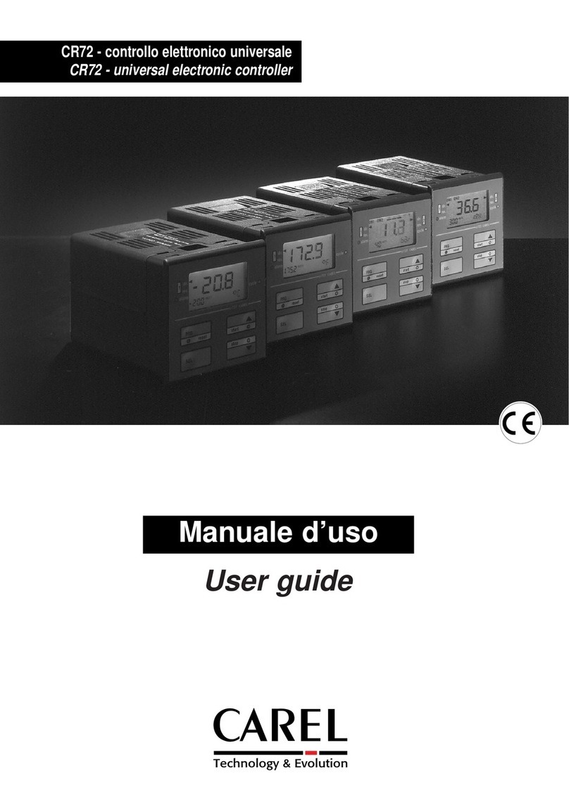
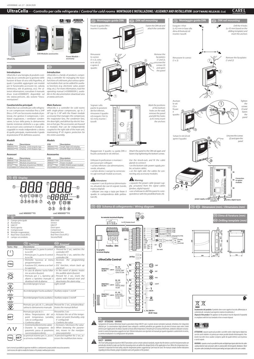
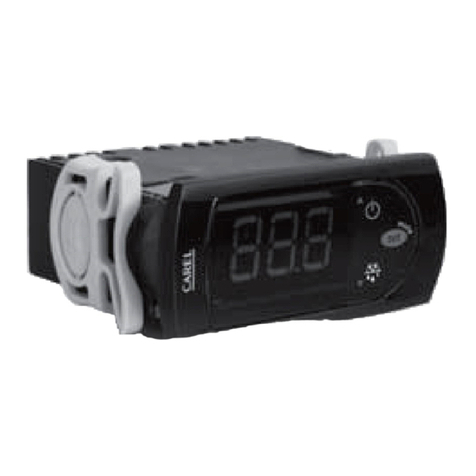
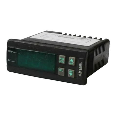
  9. Carel HYVC000R0 Series User manual

Carel HYVC000R0 Series User manual

cod. +050000157 - rel. 1.0 - 08.09.2004
HYVC000R0*
Scheda per controllo elettronico fan coil /
Board for fan coil electronic controller
Vi ringraziamo per la scelta fatta, sicuri che sarete
soddisfatti del vostro acquisto.
Introduzione
Questo dispositivo permette al controllo elettronico fan coil
(Cod. HYF*******) di gestire i carichi aggiuntivi al ventilatore;
come valvole di spillamento dagli anelli di acqua calda e fredda,
pompa di circolazione, alimentazione del relè esterno per la
resistenza di riscaldamento e le richieste di acqua calda e fredda
al chiller/pompa di calore e caldaia.
Significato dei morsetti
Morsetto Significato
SUPPLY EXP Connettore per l’alimentazione dell’espansione
fan coil (tramite cavo a 2 vie)
EXP Connettore per collegamento dell’espansione
fan coil (tramite cavo a 5 vie)
N Neutro
NO4 Alimentazione elettrovalvola acqua fredda.
Uscita in tensione (L).
NO5 Alimentazione elettrovalvola acqua calda.
Uscita in tensione (L).
NO6 Contatto pulito acqua calda
NO7 Contatto pultio acqua fredda
Nota: per i relè NO 4, 5, 6 e 7 controllare le impostazioni sul
manuale d’uso fan coil.
Lunghezza max. cavi:
uscite in tensione N°4 e N°5: 5 m
uscite digitali NO6 e NO7: 30 m (come contatto pulito),
5 m (come consenso
alimentazione eventuale carico).
Avvertenze d’installazione
• Effettuare tutte le operazioni di installazione e manutenzione a
macchina non alimentata.
• Adottare precauzioni contro le scariche elettrostatiche nel
maneggiare la scheda (ES braccialetto antistatico).
• In caso di utilizzo di schede di comunicazione seriale l’impiego
dell’uscita N°7 potrebbe essere limitata alla sola bassissima
tensione. Consultare manuale d’uso.
Protezione contro le scosse elettriche
Il sistema composto dalla scheda controllo (HYFC******) e dalle
altre schede opzionali (HYVC000R0*, HYPA******, HYIR******,
HYSC00F0C*, schede seriali pCO, ecc.) costituisce un
dispositivo di comando da incorporare in apparecchiature di tipo
classe I o II. La classe relativa alla protezione contro le scosse
elettriche dipende dalla modalità con cui viene eseguita
l'integrazione del dispositivo di comando nella macchina
realizzata dal costruttore.
La protezione contro i cortocircuiti deve essere garantita dal
costruttore dell'apparecchiatura in cui il dispositivo di comando
viene integrato o dall’installatore finale.
Interfaccia utente e modifica parametri
Per l’impostazione dei parametri è richiesto l’utilizzo della scheda
fan coil e di uno dei seguenti dispositivi: telecomando, pannello
LCD o scheda seriale.
65
20
LEGGI E CONSERVA
QUESTE ISTRUZIONI
READ AND SAVE
THESE INSTRUCTIONS
Dimensioni ed ingombri (mm)
GB (mm)
ingombro scheda
HYFC0*
16,23 20,45
95
58,32
16,23
HYVC0*
160
52,81 62,99 44,19
160
52,81 74,48 32,71
95
57,90 20,87
Thank you for having chosen this product. We trust
you will be satisfied with your purchase.
Introduction
This device allows the fan coil electronic controller
(Code HYF*******) to control the other loads in addition to the
fan; as bleed valves in the hot and cold water loops, pumps,
power supply to the external relays for the heaters and the hot
and cold water requests to the chiller/heat pump and boiler.
Terminal meaning
Terminal Meaning
SUPPLY EXP Fan coil expansion power supply connector
(2-wire cable)
EXP Connector for the fan coil expansion
(5-wire cable)
N Neutral
NO4 Cold water solenoid valve power supply.
Voltage output (L).
NO5 Hot water solenoid valve power supply.
Voltage output (L).
NO6 Hot water voltage-free contact
NO7 Cold water voltage-free contact
Note: check the setting of the NO relays 4, 5, 6 and 7 in the fan
coil user manual.
Max cable length:
voltage outputs NO4 and NO5: 5 m
digital outputs NO6 and NO7: 30 m (voltage-free contact),
5 m (to enable power supply to
any loads).
Installation guidelines
• All installation and maintenance operations must be carried out
with the unit off.
• Adopt precautions against electrostatic discharges when
handling the board (e.g. antistatic bracelet).
• If using serial communication cards, output No7 may be limited
to very low voltage uses only. Consult the user manual.
Protection against electric shock
The system made up of the control board (HYFC*****) and the
other optional cards (HYVC000R0*, HYPA******, HYIR******,
HYSC00F0C*, pCO serial cards etc..) constitutes a control
device to be incorporated into class I or II units. The class of
protection against electric shock depends on how the control
device is integrated into the unit built by the manufacturer.
Protection against short-circuits must be guaranteed by the
manufacturer of the unit that the control device is integrated into
or by the installer.
User interface and parameter settings
To set the parameters, the fan coil board and one of the following
devices are required: remote control, LCD panel or serial card.
CAREL S.p.A.
Via dell’Industria, 11 - 35020 Brugine - Padova (Italy)
Tel. (+39) 0499716611 – Fax (+39) 0499716600
http://www.carel.com – e-mail: [email protected]
CAREL si riserva la possibilità di apportare modifiche o cambiamenti ai propri prodotti senza alcun preavviso.
CAREL reserves the right to modify the features of its products without prior notice.
cod. +050000157 - rel. 1.0 - 08.09.2004
Caratteristiche tecniche
Alimentazione 230 Vac, -15/10%; 50/60 Hz
Massima potenza assorbita (escluso carichi
dei relè): 1.5 VA
Morsetti a vite Tensione max: 230 V
Sezione cavi: 14-22 AWG
La corrente assorbita dalla rete (somma delle
correnti assorbite dai carichi, dal fan coil,
dall’espansione e dal modulo esterno) non
deve superare i 6 A.
Uscite relè Corrente massima a 250 Vac:
N°4, 5, 6 e 7 - EN60730: Resistivo 2 A,
Induttivo: 2 A cos(
ϕ
)=0.4 60000 cicli
- UL: Res 2 A, 1 FLA , 6 LRA
cos (
ϕ
)=0.4 30000 cicli
Per le uscite in tensione N°4 e N°5 rispettare
i limiti massimi descritti nella casella “Morsetti
a vite”.
Tipo di azione micro-interruzione dei relè: 1C
Isolamenti Isolamento tra Bassa (uscite relè) e
bassissima tensione: Rinforzato
Isolamento tra uscite in tensione N°4,N°5 e
uscite N°6,N°7: Rinforzato
Isolamento tra uscite N°6 e N°7: Rinforzato.
In caso di utilizzo di schede seriali l’impiego
dell’uscita N°7 potrebbe essere limitata alla
sola bassissima tensione.Consultare
manuale d’uso.
Grado di protezione IP00
Condizioni di stoccaggio -20T80 °C, umidità 80% U.R.
non condensante
Condizioni di funzionamento 0T60 °C, umidità <90% U.R.
non condensante
Grado di inquinamento Normale
Cat. di resistenza al calore e
al fuoco: D
PTI dei materiali di
isolamento: tutti i materiali hanno PTI
≥
250
Periodo delle sollecitazioni
elettriche delle parti isolanti: lungo
LL N
DI5 B1 B2 B3
DIP
LN
N N No3 No2
N
N N No7 No7No6 No6
valvola
acqua
fredda
cold
water
valve
valvola
acqua
calda
hot
water
valve
contatto
acqua
calda
hot
water
contact
EXP
SUPPLY
EXP
contatto
acqua
fredda
cold
water
contact
HYFC00000*
HYPA0
HYVC0*
No4 No5
Schema di collegamento
Connection diagram
Technical specifications
Power supply 230 Vac, -15/10 %; 50/60 Hz
Maximum power input (excluding the relay
loads): 1.5 VA
Screw terminals Max voltage: 230 V
Cable cross-section: 14-22 AWG
The total current input (the sum of the
current input of the loads, the fan coil, the
expansion and the external module) must
not exceed 6 A.
Relay outputs Maximum current at 250Vac:
N°4, 5, 6 and 7 - EN60730: Resistive 2A,
Inductive: 2A cos(
ϕ
)=0.4
60000 cycles
- UL: Res 2A, 1 FLA, 6 LRA
cos (
ϕ
)= 0.4 30000 cycles
For the voltage outputs N°4 and N°5,
observe the maximum limits described under
“Screw terminals”.
Type of relay disconnection or
microswitching: 1C
Insulation Insulation between low (relay outputs) and
very low voltage parts: Reinforced
Insulation between voltage outputs N°4, N°5
and outputs N°6, N°7: Reinforced
Insulation between outputs N°6 and N°7:
Reinforced. If using serial cards, output N°7
may be limited to very low voltage uses only.
Consult the user manual.
Index of protection IP00
Storage conditions -20T80°C, 80%
rH non-condensing
Operating conditions 0T60°C, <90%
rH non-condensing
Degree of pollution Normal
Cat. of resistance to fire
and heat: D
PTI of insulating materials: all the materials have PTI
≥
250
Period of stress across the
insulating parts: long

Other Carel Controllers manuals

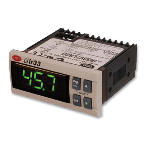
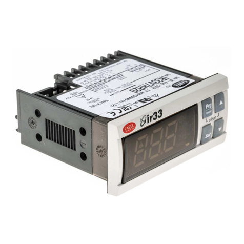
Carel IR33V7HR20 User manual

Carel

Carel IR33V7HR20 User manual

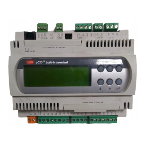
Carel pCO1 series User manual

Carel

Carel pCO1 series User manual

Carel mboss Manual

Carel

Carel mboss Manual

Carel UltraCella Instruction Manual

Carel

Carel UltraCella Instruction Manual

Carel MPXPRO User manual

Carel

Carel MPXPRO User manual

Carel pRack pR300T User manual

Carel

Carel pRack pR300T User manual

Carel FCS Series User manual

Carel

Carel FCS Series User manual

Carel MRK0000000 User manual

Carel

Carel MRK0000000 User manual

Carel SmartCella 3PH User manual

Carel

Carel SmartCella 3PH User manual

Carel EVD4 User manual

Carel

Carel EVD4 User manual

Carel pCO2 Series User manual

Carel

Carel pCO2 Series User manual

Carel UltraCella WB000S F0 Series Instruction Manual

Carel

Carel UltraCella WB000S F0 Series Instruction Manual

Carel pCO1 series User manual

Carel

Carel pCO1 series User manual

Carel FCP/1 User manual

Carel

Carel FCP/1 User manual

Carel MCH200*03 User manual

Carel

Carel MCH200*03 User manual

Carel pRack PR100 User manual

Carel

Carel pRack PR100 User manual

Carel pCO3 series User manual

Carel

Carel pCO3 series User manual

Carel pCO Series User manual

Carel

Carel pCO Series User manual

Carel ir33+ FMC User manual

Carel

Carel ir33+ FMC User manual

Carel ir33 smart User guide

Carel

Carel ir33 smart User guide

Carel pCO User manual

Carel

Carel pCO User manual

Carel compactSteam CHF User manual

Carel

Carel compactSteam CHF User manual

Carel PCOXS User manual

Carel

Carel PCOXS User manual

Carel pCO5+ User manual

Carel

Carel pCO5+ User manual

Popular Controllers manuals by other brands

Berner Intelliswitch Gen4 instruction manual

Berner

Berner Intelliswitch Gen4 instruction manual

Deif ASC Series Commissioning Guide

Deif

Deif ASC Series Commissioning Guide

Rain Bird ESP Installation, programming & operation guide

Rain Bird

Rain Bird ESP Installation, programming & operation guide

FUTABA S5801 instruction manual

FUTABA

FUTABA S5801 instruction manual

YASKAWA Motoman DX200 instructions

YASKAWA

YASKAWA Motoman DX200 instructions

PXM PiXiMo 3350 manual

PXM

PXM PiXiMo 3350 manual

Greystone AIR-300 Installation and operating instructions

Greystone

Greystone AIR-300 Installation and operating instructions

HORNER APG HEXT240C115 Specifications and installation

HORNER APG

HORNER APG HEXT240C115 Specifications and installation

Johnson Controls PENN P70 Series manual

Johnson Controls

Johnson Controls PENN P70 Series manual

MORITEX MLEP-B070W2LR instruction manual

MORITEX

MORITEX MLEP-B070W2LR instruction manual

Shimadzu CBM-20A instruction manual

Shimadzu

Shimadzu CBM-20A instruction manual

MAKOT SMT-01 user manual

MAKOT

MAKOT SMT-01 user manual

Samson TROVIS 5579 Mounting and operating instructions

Samson

Samson TROVIS 5579 Mounting and operating instructions

Morningstar ProStar PS-30M-PG Operator's manual

Morningstar

Morningstar ProStar PS-30M-PG Operator's manual

Chaparral G5312/G7313 user guide

Chaparral

Chaparral G5312/G7313 user guide

EMS ENVIROSTART MEC Getting started

EMS

EMS ENVIROSTART MEC Getting started

Toro Network VP installation instructions

Toro

Toro Network VP installation instructions

Deif CGC 400 Reference book

Deif

Deif CGC 400 Reference book

manuals.online logo
manuals.online logoBrands
  • About & Mission
  • Contact us
  • Privacy Policy
  • Terms and Conditions

Copyright 2025 Manuals.Online. All Rights Reserved.