+050004141 - rel. 1.1 - 03.06.2009
PJS1* easy - ミルクチラー用電子コントローラ / electronic controller for milk chiller
寸法 (mm) / Dimensions (mm)
71x29
10
3
33
74
81
36
58
65,29
28.5
パネル取付け / Panel mounting
+ドライバ
締め過ぎに
注意
do not tighten
excessively
前面取付け (2本のねじで、 ø 2,5x12 mm) / Front (with 2 screws ø 2,5x12 mm)
背面取付け (2個の樹脂製ブラケットで) / Rear (with 2 quick-fit side brackets)
概要説明
LED ディスプレイを持っています。
型式:
• PJS1Y0P*: 16 Aのコンプレッサ制御リレー、8 Aアジテータ制御リレー
• PJS1Y0V*: 16 Aのコンプレッサ制御リレー、8 Aアジテータ制御リレー、8 Aの補助リレー
• PJS1Y0H*: 2 HPのコンプレッサ制御リレー、8 Aアジテータ制御リレー
• PJS1Y0G*: 2 HPのコンプレッサ制御リレー、8 Aアジテータ制御リレー、8 Aの補助リレー
注記: 型式のY= リレーは電子的に内部接続されています。
技術仕様
供給電源 (*) 230 Vac +10 /-15% 50/60 Hz; 115 Vac +10 /-15% 50/60 Hz
12 Vac +10/-15% 50/60 Hz クラス 2; 12 Vdc +10/-20% クラス 2
定格出力
入力 NTCセンサ
第3センサとしてデジタル入力
リレー出力 (*) 2 Hpリレー UL: 12 A Res. 12 FLA 72 LRA - 240 Vac (***),
EN60730-1: 10(10) A 250 Vac (**)
16 Aリレー UL: 12 A Res. 5 FLA 30 LRA - 240 Vac C300,
EN60730-1: 12(2) A NO/NC, 10(4) A 60 °Cまで NO,
2(2) A CO - 250 Vac
8 Aリレー UL: 8 A Res. 2 FLA 12 LRA - 240 Vac C300,
EN60730-1: 8(4) A NO, 6(4) A NC, 2(2) A CO - 250 Vac
センサのタイプ CARELのNTC標準センサ 10 KΩ at25 °C
接続 (*) 断面積 0,5 mm2~1,5 mm2のケーブル用ねじ端子。ファストン端子、又は、クリンプ端子 (ケーブ
ル断面積 2,5 mm2まで)。端子毎の定格最大電流は 12 A
アセンブリ (*) ターミナル: 前面からねじで、背面からはブラケットで
ディスプレイ 3桁LED表示 (-199…999)、小数点表示; 6個のLEDで状態表示
使用条件 -10T50 °C - 相対湿度 <90% 、結露無き事
保管条件 -20T70 °C - 相対湿度 <90%、結露無き事
測定範囲 -50T90 °C (-58T194 °F) - 分解能 0,1 °C/°F
前面パネルの保護等級 タイプ1のガスケット使用により: IP65
ケース 樹脂製ターミナル、81x36x65 mm
電気ショック保護の分類 クラス II、適切な使用環境において
環境汚染 ノーマル
絶縁材のPTI(保証トラッキング指数)
絶縁部品間のストレス期間 長期
耐熱耐火性カテゴリ カテゴリ D (UL94 - V0)
電圧サージに対するイミュニティ カテゴリ 1
アクションタイプと切断 1Cリレー接点
リレーの自動操作サイクル数 (*)
100.000 オペレーション
30.000 オペレーション (250 Vac)
ソフトウェアのクラス クラス A
コントローラの洗浄 中性洗剤と水のみ使用可能
ケーブル最大長 シリアル: 1 km; センサ: 30 m; リレー: 10 m
警告:電源ケーブルはコントローラの底部から、或いは、センサから 3 cm以内に取付けることは禁止です。 接続に
は銅線のみを使って下さい。
(*) 機能は型式によって異なります。
パラメータ表
パラメータ
単位
パスワード
センサ関連のパラメータ
測定安定性
表示対象のセンサ/入力の選択 (1= センサ1, 2= センサ2, 3= センサ3)
温度単位の選択 °C / °F ( 0 = °C; 1 = °F)
小数点表示を無効に
センサ 1の較正
F -12,7 12,7 0,0 °C/°F
/C2
センサ 2の較正
F -12,7 12,7 0,0 °C/°F
/C3
センサ 3の較正
制御パラメータ
設定値 1
制御ディファレンシャル 1 (設定値 1に対して)
設定値 2
制御ディファレンシャル 2 (設定値2に対して)
設定可能最少設定値 (設定値1)
設定可能最大設定値 (設定値1)
設定可能最少設定値 (設定値2)
設定可能最大設定値 (設定値2)
操作モード 1= ダイレクト; 2= リバース
夜間設定値の自動変更
コンプレッサ関連パラメータ
始動時のコンプレッサとファンの起動遅延
コンプレッサ起動間の最短時間
コンプレッサの最短停止時間
コンプレッサの最短運転時間
コンプレッサ保安 (デューティ設定)
継続サイクル持続時間
継続サイクル後のアラームバイパス時間
アラーム関連パラメータ
アラームとファンのディファレンシャル
低温アラーム閾値/偏差 (AL= 0 アラーム無効)
高温アラーム閾値/偏差 (AH= 0 アラーム無効)
高低温アラーム遅延
デジタル入力設定
外部アラーム検知遅延
高凝縮温度アラーム
C -50,0 150,0 70,0 °C/°F
AE
高凝縮温度アラームディファレンシャル
高凝縮温度アラーム遅延
アジテータ関連パラメータ
冷却サイクル後の撹拌時間
撹拌サイクル間のインターバル
手動での短時間撹拌持続時間
手動での長時間撹拌持続時間
アジテータの自動モード
その他の設定
シリアルアドレス
AUX出力設定
0= 機能の設定無し
1= アラーム出力: 通常通電
2= アラーム出力: 通常非通電
3= aux出力はデジタル入力で [A4=6/7/8]
デジタル入力開= aux非通電
デジタル入力閉= aux 通電
キーパッドを有効に
0= キーパッド無効
- F パラメータはリードオンリー
- C パラメータは変更可能 (PS)
- SETボタンでの設定値変更不可
-手動撹拌不可
-継続サイクル不可
-設定値1/設定値 2の変更不可
1= キーパッド有効
2= 設定値1/設定値2をSETでの変更以外についてはキーパッド有効
ブザーを無効に 0= ブザー有効 (ON); 1= ブザー無効 (OFF)
監視システムからのデジタル入力コード
型式に応じたEasy Setの選択、マニュアル参照
ディスプレイと機能
通常操作時にコントローラは、パラメータの /4 (=1 庫内温度センサ, =2 第2センサ, 3= 第3センサ)で設定したセンサの
感知温度を表示します。さらに、LEDで制御機能の実行状態を表示します (Tab. 1参照)。また、3
つのボタンでいくつかの機能を実行/停止できます (Tab. 2参照)。
LEDと関連機能
アイコン 機能 通常操作 始動時
点滅
コンプレッサ on off 要求
アジテータ on off 要求
出力on 出力off
アラーム 全て アラーム無し
ボタンで実行できる機能
ボタン 通常操作 始動時
単独ボタンを押す 同時に
押す
3秒以上押す: 設定値1と設定値2間の設定値を変更 (設定値
を1から2に、或いは2から1へ変更するかによってディ
スプレイは ‘1t2’ 又は、 ‘2t1’ を表示)
同時に押す
ことで
継続サイクルを
始動/停止
します。
手動撹拌サイクルがアクティブでない時:
• 3秒以下でボタンを放すと短時間手動サイクルを選択
(パラメータのP3を参照)
•3秒以上でボタンを放すと長時間手動サイクルを選択
(パラメータのP4を参照)
手動撹拌サイクルを実行中の場合、3秒以上押すと停止でき
ます。
同時に
押すと
パラメータ
リセット操作
を開始
1秒押しで
ファームウェアの
バージョンを
表示
•1秒押す: アクティブな設定値を表示/設定 (T1/T2ボタンで選択し
た設定値1又は、設定値2)
•3秒以上押す: パラメータ設定メニューにアクセス(パスワード ‘22’を入力)
- アラーム (ブザー)をミュートに
1秒押しで
現在のEZY
セットをリセット
アクティブ設定値の設定 (希望温度)
•設定値1又は、設定値2をT1/T2ボタンで設定
• SETを1秒押すと少しして設定値が点滅を開始
• UP/DOWNボタンで数値を変更
• SETを押して新しい値を確定
継続サイクル
UP とDOWNボタンを同時に3秒以上押します。
アジテータ出力制御
自動アジテータ制御
パラメータのP5で自動アジテータ制御モードを選択できます。
•コンプレッサに依存 (P5=0):
コンプレッサON: アジテータ実行
コンプレッサOFF: コンプレッサが停止してからアジテータは P1の時間撹拌を続
け、P1とP2の時間に応じて撹拌は実行/停止のサイクルを行います。
P1=0の場合、常にアジテータはOFFです。P2は意味を持ちません。
P2=0の場合、コンプレッサがP1時間だけ停止した後、アジテータは撹拌を続けます。
P2 P2 P2
次の実行/停止サイクルは無視されます。
P1 P1 P1
コンプレッサ
アジテータ
•コンプレッサからは独立して撹拌サイクルが ON (P5=1)の場合に始まります。
電源を入れると、P1 とP2の時間に応じてアジテータが実行/停止されます。P2=0の場合、アジテータは常
にONで、P1は意味を持ちません。P1=0 でP2がゼロ以外の数値の場合、アジテータは常にOFFです。
P2
P1
P2 P2
P1 P1
電源 ON
アジテータ
•コンプレッサからは独立して OFF (P5=2)の時に、撹拌サイクルが始まります。 電源投入時にP1 とP2の
時間に応じて撹拌サイクルを開始/停止します。P1=0 ではアジテータは常にOFFです。P2は意味がありま
せん。P2=0 でP1がゼロ以外の数値の場合アジテータは常にONです。
P2 P2 P2
P1 P1 P1
電源 ON
アジテータ
手動アジテータ制御
短時間、又は、長時間撹拌サイクルはキーパッドの ボタンを押して始動できます。あるいは、遠隔
撹拌ボタンとしてデジタル入力を設定していればデジタル入力経由で始動できます。短時間、長時間
撹拌サイクル時間は P3 とP4で設定します。P3 又は、 P4がゼロの場合そのサイクルは実行されません。
•手動撹拌サイクルは時間が 終了する前でもキーパッドから、又は、デジタル入
力経由で停止できます。
•手動撹拌サイクルが実行中にはアジテータアイコンが点滅し、手動運転中であるこ
とが分かります。
アジテータデジタル入力からの遠隔制御
•デジタル入力をパラメータのA4で設定し、閉の状態であればアジテータをデジタル入力で制御できま
す。
デジタル入力設定 機能
遠隔アジテータ制御 開: アジテータ管理を自動/ 手動制御で (キーパッドから)
閉: アジテータ実行
遠隔アジテータボタン 遠隔ボタンがアジテータボタン の代わりとなります。
遠隔設定値セレクタ 設定値 (設定値1 、設定値2)のキーパッドからの選択を無効に
開: 設定値1
閉: 設定値2
アジテータは常にキーパッドから実行できますが、デジタル入力経由の場合はパラメータのA4が適切に
設定されている場合だけに実行できます。
撹拌サイクル
イベント 撹拌サイクル 表示
- ボタン を3秒未満で放します。
- デジタル入力 (適切に設定されている場合)は、3秒
未満閉じます。
短時間
(時間はP3で設定)
- ボタン を3秒以上押します。
- デジタル入力 (適切に設定されている場合)は、3秒以上
閉じます。
長時間
(時間はP4で設定)
自動、手動、遠隔撹拌制御は各々独立しています。自動、手動、遠隔の内の少なくとも一つの制
御が実行要求していればアジテータ出力はアクティブです。一方、全ての制御がoffの時は、アジテータ出力
は無効です。
デジタル入力設定
説明
入力は非アクティブ
外部アラーム (A7=0 即座, A7>0 遅延)
デジタル入力開 = アラーム; デジタル入力閉 = ok
遠隔アジテータ制御:
デジタル入力開 = アジテータ出力は自動/手動制御で管理
デジタル入力閉 = アジテータ出力アクティブ
遠隔アジテータボタン: デジタル入力がアジテータボタン と同じように使えます。
カーテンスイッチ、又は、夜間モード:
デジタル入力開 = 通常時の設定値
デジタル入力閉 = 夜間設定値 (r4を設定値に追加)
遠隔設定値セレクタ: キーパッドからの選択は無効 (ボタン ʻ1t2ʼ 又は、 ʻ2t1ʼ を押すと
ディスプレイにはコードが表示されます)
デジタル入力開 = 設定値1; デジタル入力閉 = 設定値2
AUX出力制御をH1=3で(AUX出力が利用できる時だけ)
デジタル入力開 = AUXリレー off; デジタル入力閉 = AUXリレー on
ドアボタン、アジテータはoff
• 即アラーム (A7=0) 又は、アラーム遅延 (A7>0)
• AUXリレー制御、H1=3の場合
デジタル入力開 = ドア開; デジタル入力閉 = ドア閉
ドアボタン、アジテータとコンプレッサはoff
• 即アラーム (A7=0) 又は、アラーム遅延 (A7>0)
• AUXリレー制御、H1=3の場合
デジタル入力開 = ドア開; デジタル入力閉 = ドア閉
ダイレクト (冷却) / リバース (加熱) モードの選択
デジタル入力開 = ダイレクト; デジタル入力閉 = リバース
汚染凝縮器アラーム用センサ
庫内商品用センサ
タイプ F (頻繁) とタイプ C (設定)パラメータへのアクセスと設定
1. SETを3秒押す。 (“PS”をディスプレイに表示)
2. • タイプF とC のパラメータにアクセスするにはパスワードの“22” をUP/DOWNボタンで入力
• タイプ F パラメータのみへのアクセスではSETを押すだけです。 (パスワードは不要)
3. パラメータメニュー内をスクロール移動するには UP/DOWNボタンを使います。
4. パラメータの表示/表示中のパラメータの設定にはSETを押します。UP/DOWNで数値を変更して
最後に確定のSETを押します。 (パラメータメニューに戻ります)。
全ての新しい数値を保存してパラメータメニューを終了するには SETを3秒押します。変更した値
を保存せずに終了するには、いずれのボタンも押さずに60秒以上放置します(タイムアウト)。
アラーム表
アラームコード ブザーとアラームリレー
説明 関連パラメータ
アクティブ
センサ 1エラー = 制御
非アクティブ
センサ 3エラー
アクティブ
外部アラーム
アクティブ
ドア開アラーム
アクティブ
低温アラーム
アクティブ
高温アラーム
非アクティブ
ユニットパラメータエラー
非アクティブ
操作パラメータエラー
非アクティブ
汚染凝縮器プリアラーム
アクティブ
汚染凝縮器アラーム
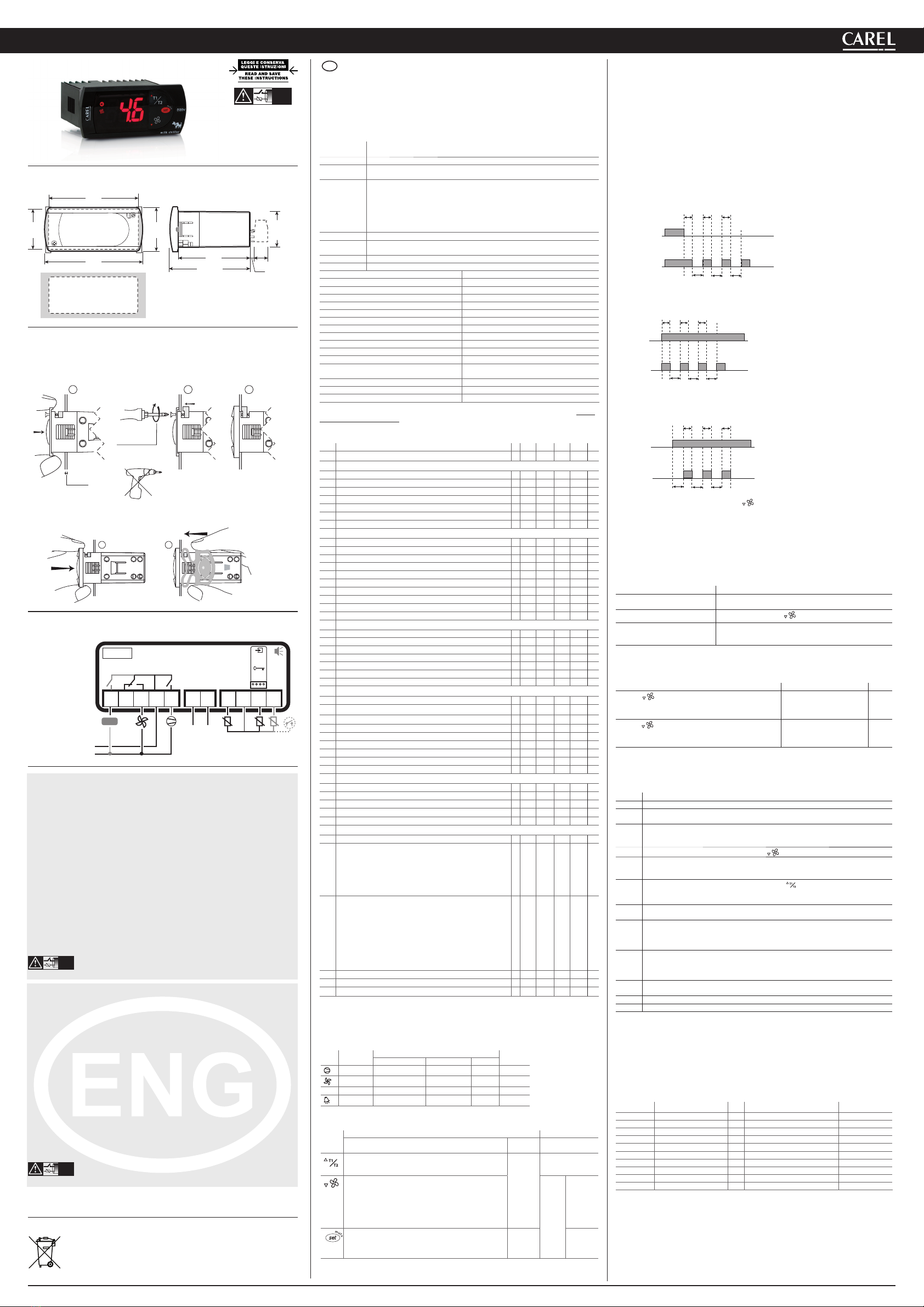
PJS1Y0*
1 2 3 4 5 6 7
9 10 118
L
N
L N
DI / NTC
AMB. T.
NTC
PROBES
or
SERIAL
CONV
PROG.
KEY
-10T50
230 Vac or
115 Vac or
12 Vac/Vdc
AUX
配線図 / Electrical connections
製品の廃棄について
当該製品はご使用国の廃棄ルールに従って処分をお願いします。
Disposal of the product
The appliance (or the product) must be disposed of separately in accordance with the local waste
disposal legislation in force.
重要な警告
CAREL製品は技術の粋を集めた装置であり、その操作については製品に同梱のドキュメント記載されてい
ます。又は、購入前に弊社ウェブサイトwww.carel.comからダウンロードいただけます。ユーザー
(製造メーカー、開発者、最終製品の設置業者)は、その特定最終設置、装置の希望結果に到達すべく
製品の設定を行いますが、これに関する全ての責任とリスクをご負担いただくことを前提といたして
おります。ユーザーマニュアルに記載されている内容を順守いただけない場合、製品の故障原因となりま
す。このような場合、CARELでは責任を負うことができません。ユーザーは、製品の説明書に記載のあ
る方法でのみご使用ください。CARELの製品保証の詳細は、前記のウェブサイトをご参照ください。特定
ユーザーとの個別契約についてはそちらに準じます。
安全基準
c関連の欧州基準に適合しています。取付け時の注意事項をまとめました。
•接続ケーブルは90°Cまでの絶縁性を必要とします。
• 12 Vacバージョンの型式にはクラス IIの変圧器を使用します。イミュニティ基準(サージ)、EN 61000-4-4, EN
61000-4-5, EN 61000-4-11, EN 61000-4-6, EN 60730-1に適合するには、特定の変圧器を使用する必要が
あります。(CARELまでお問合わせください)。12 Vac/dcバージョンの型式には、電源供給とリレー出力
間で二重絶縁を保証できないため安全低電圧負荷のみ (42 V有効定格値まで)を使用できます。
•ケースと近傍の導電部品間の距離は 10 mm以上離して下さい。
•デジタル入力接続とアナログ入力接続間の距離が30 m以下の場合、イミュニティ基準に適合させるた
め、ケーブル間の距離を離す等の適切な手段を講じて下さい。
出力の接続ケーブルが低電圧部品と接触しないよう注意して下さい。
NO POWER
& SIGNAL
CABLES
TOGETHER
READ CAREFULLY IN THE TEXT!
警告: 電磁干渉を避けるために、センサとデジタル入力信号ケーブルは誘導負荷のケーブル
や電源ケーブルからなるべく距離をおいてください。同じコンジット内に電源ケーブ
ル(電源パネルの配線を含む)と信号ケーブルを納めないでください。
IMPORTANT WARNINGS
The CAREL product is a state-of-the-art device, whose operation is specifi ed in the technical documentation
supplied with the product or can be downloaded, even prior to purchase, from the website www.carel.com.
The customer (manufacturer, developer or installer of the fi nal equipment) accepts all liability and risk
relating to the confi gura-tion of the product in order to reach the expected results in relation to the specifi c fi
nal installation and/or equipment.
The failure to complete such phase, which is required/indicated in the user manual, may cause the fi nal
product to malfun-ction; CAREL accepts no liability in such cases.
The customer must use the product only in the manner described in the documentation relating to the
product.
The liability of CAREL in relation to its products is specifi ed in the CAREL general contract conditions,
available on the website www.carel.com and/or by specifi c agreements with customers.
Safety standards
compliant with the relevant uropean standards. Installation precautions:
the connection cables must guarantee insulation up to 90 °C;•
for 12 Vac versions use Class II transformers. To ensure compliance with the immunity standards (surge) - EN 61000-4-4,•
EN 61000-4-5, EN 61000-4-11, EN 61000-4-6, EN 60730-1-, the transformer must be one of the models specified, (see
CAREL Price List). For the 12 Vac/dc versions, as double insulation cannot be guaranteed between the power supply
and the relay outputs, only use safety low voltage loads (up to 42 V effective rated value);
ensure a space of at least 10 mm between the case and the nearby conductive parts;•
digital and analogue input connections less than 30 m away; adopt suitable measures for separating the cables so as to•
ensure compliance with the immunity standards.
Secure the connection cables of the outputs so as to avoid contact with very low voltage parts.
NO POWER
& SIGNAL
CABLES
TOGETHER
READ CAREFULLY IN THE TEXT!
WARNING: separate as much as possible the probe and digital input signal
cables from the cables carrying inductive loads and power cables to avoid
possible electromagnetic disturbance. Never run power cables (including the
electrical panel wiring) and signal cables in the same conduits.
NO POWER
& SIGNAL
CABLES
TOGETHER
READ CAREFULLY IN THE TEXT!
JPN PJS1* (型式 S, C, M, Y, X) は、ミルクチラー様に開発された電子式コントローラシリーズです。


