cod. +050003270 - rel. 1.0 - 26.05.2004
PCO100TLN0 / PCO100MPB0 / PCO100FD10
scheda seriale tLAN, MP-Bus e RS485 per pCO1/
tLAN, MP-Bus and RS485 serial card for pCO
1
Vi ringraziamo per la scelta fatta, sicuri che sarete soddisfatti del vostro
acquisto.
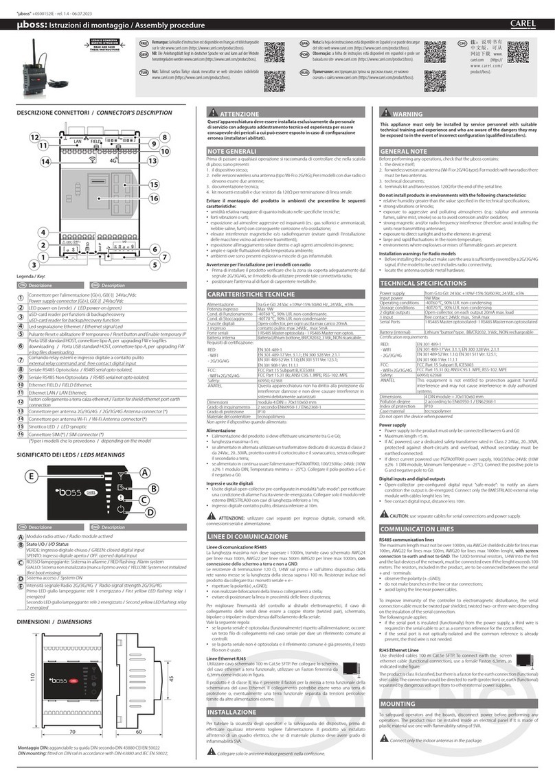
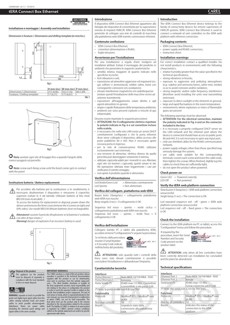
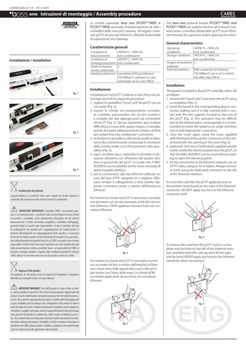
Schede seriali per collegamento ad una rete“field bus”
Le schede opzione Field bus realizzano una interfaccia di tipo seriale che permette al
pCO1di comunicare con altri dispositivi attraverso vari standard. Infatti le opzioni
tLAN, MP bus e RS485 collegano il pCO1ad una rete di dispositivi tra i quali
attuatori, sonde, espansioni o terminali.
Montaggio
Con riferimento alle Figg. 1...4, il collegamento dell’opzione al pCO1si ottiene
secondo la seguente procedura:
1. Con un cacciavite, togliere lo sportellino "Analog Selection" del controllore
elettronico (Fig. 1);
2. Se necessario selezionare il tipo di ingressi analogici tramite il relativo dip switch.
L’alloggiamento della scheda opzione non permetterà di eseguire questa
operazione in seguito.
3. Con un tronchesino, eliminare dallo sportellino la parte destra plastica
prefratturata, ottenendo il foro corrispondente all'uscita dei connettori (Fig. 2);
4. Inserire la scheda opzione nel corrispondente connettore a pettine facendo
attenzione ai collegamenti elettrici e che stia in battuta ai due appoggi plastici
solidali al contenitore del pCO1(Fig. 3);
5. Richiudere lo sportellino mediante il cacciavite facendo coincidere il connettore o i
connettori della scheda opzione con il foro eseguito sullo sportellino (Fig. 4).
Opzione seriale RS485 elettricamente isolata
L’opzione PCO100FD10 consente il collegamento, attraverso un’interfaccia
elettricamente isolata, del pCO1ad una rete RS485 tramite il connettore a morsetti
estraibili presente sulla scheda. La funzione realizzata è quella di tipo MASTER (tipo
supervisore), è quindi possibile collegare altri pCO o altri dispositivi di tipo SLAVE. Il
significato dei pin sul connettore è evidenziato dalla serigrafia presente sulla scheda.
Il numero massimo di dispositivi collegabili con questo tipo di connessioni è pari a
207.
Qualora la scheda opzione occupi l'ultima posizione sulla linea seriale di supervisione
e la linea abbia una lunghezza superiore ai 100 m si colleghino ai capi dei pin le
resistenze di chiusura linea del valore di 120
Ω
- 1/4 W come rappresentato in Fig. 5.
Opzione tLAN e PST
L’opzione PCO100TLN0 consente il collegamento del pCO1ad una rete tLAN tramite
due distinti connettori.
Il connettore 1 permette di collegare il pCO1ad una rete tLAN (Fig. 6A). Attraverso
questa connessione ed un applicativo opportunamente configurato in modalità TLAN
MASTER il pCO1può interagire con le pCO I/O Expansion (versione tLAN -
PCOE00TLN0) o con altri pCO dotati di connessione tLAN, configurati in modalità
tLAN SLAVE. Il significato dei pin sul connettore è evidenziato in Fig. 6A. Il numero
massimo di dispositivi collegabili con questo tipo di connessioni è pari a 5.
Il connettore 2 permette invece il collegamento di un terminale PST (Fig. 6B).
Attraverso questa connessione e un applicativo opportunamente configurato, il pCO1
può interagire con un terminale PST.
Thank you for having chosen this product.We trust you will be satisfied
with your purchase.
“Field bus”serial cards for network connection
The optional Field bus cards create a serial interface that allows the pCO1to
communicate with other devices via various standards. In fact, the tLAN, MP bus and
RS485 options connect the pCO1to a network of devices, including actuators, probes,
expansions or terminals.
Assembly
With reference to Figs. 1 to 4, the optional card is connected the pCO1according to
the following procedure:
1. Using a screwdriver, remove the "Analog Selection" cover on the electronic
controller (Fig. 1);
2. If necessary, select the type of analogue inputs using the special dipswitch.Fitting
the optional card first will make it impossible to perform this operation.
3. With a pair of cutting nippers, cut out the pre-cut plastic section from the cover,
making an opening for the connectors to pass through (Fig. 2);
4. Insert the optional card in the corresponding plug-in connector, paying attention to
the electrical connections, and making sure the card is pushed all the way up
against the two plastic supports on the pCO1case (Fig. 3);
5. Close the cover again using the screwdriver, making sure the connector or the
connectors on the optional card pass through the hole made in the cover (Fig. 4).
Electrically insulated RS485 serial option
The PCO100FD10 option is used to connect the pCO1, via an electrically insulated
interface, to an RS485 network, using the connector with removable terminals on the
card.The controller consequently acts as the MASTER (i.e. supervisor), and therefore
other pCO controllers or SLAVE devices can also be connected.The meaning of the
pins on the connector are denoted by the silk-screening on the card.A maximum of
207 devices can be connected using this type of connection.
If the optional card occupies the last position on the supervisor serial line and the line
is longer than 100m, the line must be terminated by connecting a 120
Ω
- 1/4W
resistor to the terminal pins, as shown in Fig. 5.
tLAN and PST option
The PCO100TLN0 option is used to connect the pCO1to a tLAN network using two
separate connectors.
Connector 1 is used to connect the pCO1to a tLAN network (Fig. 6A). Using this
connection and a suitably-configured application in TLAN MASTER mode, the pCO1
can interact with the pCO I/O expansion (tLAN version - PCOE00TLN0) or with other
pCO controllers fitted with a tLAN connection, configured in tLAN SLAVE mode.The
meaning of the pins on the connector is shown in Fig. 6A. A maximum of 5 devices
can be connected using this type of connection.
Connector 2, on the other hand, is used to connect a PST terminal (Fig. 6B). Using
this connection and a suitably-configured application, the pCO1can interact with a
PST terminal.
Fig. 1
Fig. 2


