LAPP ETHERLINE GUARD PM03T User manual

U.I. Lapp GmbH | Schulze-Delitzsch-Straße 25 | D-70565 Stuttgart | Germany
Phone +49 (711) 78 38 - 01 | Fax +49 (711) 78 38 - 26 40 | info@lapp.de | www.lappkabel.de
ETHERLINE® GUARD PM03T / PM02TWA
Operating instructions
Issue 1.0 | 11.04.2022 | from firmware V 1.00
Link to the latest version of
the operating instructions

Notes
All rights reserved, including those of translation, reprinting and reproduction of these operating
instructions or parts thereof.
No part of these operating instructions may be reproduced, processed, duplicated or distributed in any
form (photocopy, photograph, microfilm or other process), not even for the purpose of teaching, or using
electronic systems without the written permission of U.I. Lapp GmbH.
The latest version of the operating instructions can be found on the Internet at www.lappkabel.com
We are happy to receive suggestions for improvement and ideas.
Furthermore, we offer to send the complete corresponding source code of the respective open source
software to you and any third party as a DVD upon your request for a contribution towards costs of Euro
10,00. This offer is valid for a period of three years, calculated from the delivery of the product.
Copyright © U.I. Lapp GmbH 2022. All rights reserved. No part of this document may be reproduced,
transmitted, stored in a retrieval system, or transmitted in any form or by any means, electronic,
mechanical, photocopying, recording, or otherwise, without prior written permission. All rights reserved in
the event of patent grant, design or utility model registration.
Changes in this document:
Stand
Date
Change
1.0
04.03.2022
First Version / Firmware V1.00.18

ETHERLINE® GUARD | Issue 1e | 11.04.2022 3
Content
1General....................................................................................................................................5
1.1 Safety instructions ....................................................................................................................................5
1.2 Signs and signal words............................................................................................................................5
1.3 Target group of the operating instructions ............................................................................................6
1.4 Intended use..............................................................................................................................................6
1.5 Abuse..........................................................................................................................................................7
1.6 Assembly / Disassembly..........................................................................................................................7
1.6.1 Access restriction .................................................................................................................................7
1.6.2 Installation position and minimum distances....................................................................................7
1.6.3 Electrical installation.............................................................................................................................7
1.6.4 Protection against electrostatic discharges ......................................................................................7
1.6.5 EMC protection.....................................................................................................................................8
1.6.6 Operation...............................................................................................................................................8
1.6.7 Liability ...................................................................................................................................................8
1.6.8 Disclaimer..............................................................................................................................................8
1.6.9 Warranty ................................................................................................................................................8
1.6.10 Recycling and disposal / WEEE.....................................................................................................9
2Security recommendations.................................................................................................10
3Overview................................................................................................................................11
4Structure and connection of the ETHERLINE®GUARD................................................12
4.1 Connection of the power supply ...........................................................................................................13
4.2 Connection of the line to be monitored (DATA) .................................................................................13
4.3 Connecting the data connection (LAN / WIFI)....................................................................................14
4.4 Connection of the digital outputs (Q1/Q2)...........................................................................................14
4.5 Using the microSD card.........................................................................................................................15
5First commissioning ("teach-in")........................................................................................16
6Access to the web interface...............................................................................................19
6.1 Access via LAN.......................................................................................................................................19
6.2 Access via WIFI ......................................................................................................................................19
6.3 Initial registration.....................................................................................................................................20
6.4 Main view "Home“ ...................................................................................................................................21
7Configuration ........................................................................................................................22
7.1 Basic configuration "Settings“ ...............................................................................................................22
7.2 Ethernet configuration (LAN).................................................................................................................22
7.3 WiFi configuration...................................................................................................................................23
7.3.1 Switch WiFi operating mode.............................................................................................................24
7.3.2 Functions of the WiFi LED ................................................................................................................24

ETHERLINE® GUARD | Issue 1e | 11.04.2022 4
8Sending the cable status via MQTT..................................................................................25
9Firmware update..................................................................................................................26
10 Reset to factory setting....................................................................................................27
11 FAQ.....................................................................................................................................28
12 Technical data...................................................................................................................31
12.1 ETHERLINE GUARD with LAN connection........................................................................................31
12.2 ETHERLINE GUARD with WIFI connection .......................................................................................32
12.3 Dimensioned drawing.............................................................................................................................33
12.3.1 PM03T .............................................................................................................................................33
12.3.2 PM02TWA.......................................................................................................................................33

ETHERLINE® GUARD | Issue 1e | 11.04.2022 5
1 General
These operating instructions apply exclusively to devices, assemblies, software and services provided by
U.I. Lapp GmbH.
1.1 Safety instructions
The safety instructions must be observed in order to protect persons and living beings, material goods
and the environment from damage. The safety instructions point out possible dangers and give advice on
how to avoid dangerous situations.
1.2 Signs and signal words
If the danger notice is not observed, there is an immediate danger to the health and life of persons due to
electrical voltage.
If the danger notice is not observed, there is a probable danger to the health and life of persons.
If the danger notice is not observed, persons may be injured or harmed.
Draws attention to sources of error that can damage equipment or the environment.
Gives a hint for better understanding or to avoid mistakes.

ETHERLINE® GUARD | Issue 1e | 11.04.2022 6
1.3 Target group of the operating instructions
This description is intended exclusively for trained specialists in control and automation technology who
are familiar with the applicable national standards. For installation, commissioning and operation of the
components, it is absolutely necessary to observe the notes and explanations in these operating
instructions.
Project planning, design and operating errors can impair the proper operation of the ETHERLINE®
GUARD and result in personal injury, property damage or environmental damage.
Only adequately qualified personnel may operate the units!
The qualified personnel must ensure that the application or use of the products described complies with
all safety requirements, including all applicable laws, regulations, provisions and standards.
The minimum length of the Ethernet cable to be monitored is 2m.
Before using the unit, please check whether a newer version of the firmware is available on the website
(for more information on firmware updates, see chapter 9) is available.
1.4 Intended use
The LAPP ETHERLINE® GUARD is used for condition monitoring of Ethernet-based data lines with the
100BASE-TX transmission standard, with a focus on dynamic applications.
All components are delivered with a factory hardware and software configuration. The hardware and
software configuration to suit the application conditions must be carried out by the user. Changes to the
hardware or software configuration that go beyond the documented possibilities are not permitted and will
result in the exclusion of liability on the part of U.I. Lapp GmbH.

ETHERLINE® GUARD | Issue 1e | 11.04.2022 7
The device must not be used as the sole means of averting dangerous conditions on machinery and
equipment.
Faultless and safe operation of the unit requires proper transport, storage, set-up, assembly, installation,
commissioning, operation and maintenance.
The ambient conditions specified in the technical data must be observed.
The unit has protection level IP 20 and must be installed in an electrical operating room or a control
box/switch cabinet to protect it from environmental influences. To prevent unauthorised operation, the
doors of the switch boxes/switch cabinets must be closed and secured if necessary during operation.
1.5 Abuse
The consequences of improper use may include personal injury to the user or third parties, data
protection violations as well as property damage to the control unit, the product or environmental damage.
Only use the unit as intended!
1.6 Assembly / Disassembly
1.6.1 Access restriction
The assemblies are open equipment and may only be installed in electrical operating rooms, cabinets or
enclosures. Access to the electrical operating rooms, cabinets or enclosures must only be possible using
tools or keys and must only be permitted to instructed or approved personnel.
1.6.2 Installation position and minimum distances
The module is suitable for mounting on a top-hat rail in any position. No minimum distances need to be
observed, but accessibility for connectors and the SD card must be ensured.
1.6.3 Electrical installation
The regionally applicable safety regulations must be observed.
1.6.4 Protection against electrostatic discharges
To prevent damage caused by electrostatic discharges, the following safety measures must be followed
during assembly and service work:
•Never place components and assemblies directly on plastic objects (e.g. polystyrene, PE film) and
also avoid their proximity.

ETHERLINE® GUARD | Issue 1e | 11.04.2022 8
•Use ESD-compliant tools and clothing.
•Do not touch components and assemblies at contacts.
1.6.5 EMC protection
In order to ensure electromagnetic compatibility (EMC) in your control cabinets and in an electrically
harsh environment, the known rules of EMC-compliant construction must be observed during design and
assembly. In particular, the functional earth (FE) connection must be connected to the potential
equalisation.
1.6.6 Operation
Only operate the unit when it is in technically perfect condition. The permissible operating conditions and
performance limits must be observed.
Retrofitting, modifications or conversions to the unit are strictly prohibited.
The unit is a piece of equipment for use in industrial installations. During operation, all covers on the unit
and the installation must be closed to ensure protection against accidental contact.
1.6.7 Liability
The contents of these operating instructions are subject to technical changes resulting from the
continuous further development of the products of U.I. Lapp GmbH. In the event that these operating
instructions contain technical errors or editorial mistakes, we reserve the right to make changes at any
time and without notice.
No claims for changes to products already supplied can be made on the basis of the information,
illustrations and descriptions in this documentation. In addition to the instructions contained in the
operating instructions, the applicable national and international standards and regulations must always be
observed.
1.6.8 Disclaimer
U.I. Lapp GmbH is not liable for damage caused by improper use or application of the products.
U.I. Lapp GmbH accepts no liability for any printing errors or other inaccuracies contained in the operating
instructions, unless they are serious errors of which U.I. Lapp GmbH is already demonstrably aware.
In addition to the instructions contained in the operating instructions, the applicable national and
international standards and regulations must always be observed.
U.I. Lapp GmbH is not liable for damage caused by software that is active on the user's devices and
impairs, damages or infects other devices or processes via the remote maintenance connection and
triggers or enables undesired data transfer.
U.I. Lapp GmbH shall not be liable in the event of incorrect calculation.
1.6.9 Warranty
Report defects to the manufacturer immediately after the defect has been detected.
The warranty expires in the event of:
•Disregard of these operating instructions
•Improper use of the appliance
•Improper work on and with the unit
•Operating errors

ETHERLINE® GUARD | Issue 1e | 11.04.2022 9
•Changes to the unit
The agreements made upon conclusion of the contract under "General Terms and Conditions of U.I. Lapp
GmbH " shall apply.
1.6.10 Recycling and disposal / WEEE
LAPP complies with all legal requirements and is registered with the national registers for WEEE in
accordance with the directives.
The products described in this document are low-polluting, recyclable and meet the requirements of the
WEEE Directive 2012/19/EU for the disposal of waste electrical and electronic equipment.
The electrical appliances described are designed for the business-to-business (B2B) sector and are to be
recycled.
According to Directive 2012/19/EU on Waste Electrical and Electronic Equipment
(WEEE), such devices may not be disposed of via municipal waste disposal companies.
Therefore, do not dispose of the products at public disposal points.
For environmentally sound recycling and disposal of your old device, contact a certified
disposal company for electronic waste or your LAPP contact person.
More at www.lappkabel.de/weee.html
Note different country-specific regulations.

ETHERLINE® GUARD | Issue 1e | 11.04.2022 10
2 Security recommendations
ETHERLINE®GUARD is a network component and therefore an important element when considering
security aspects within a facility or network. Therefore, when using ETHERLINE® GUARD, observe the
following recommendations to prevent unauthorised access to installations and systems.
General:
•Ensure at regular intervals that all relevant components comply with these recommendations and,
if applicable, other internal safety guidelines.
•Evaluate your system holistically with regard to safety. Use a cell protection concept ("defence-in-
depth") with appropriate products.
•Keep yourself regularly informed about security threats to all your components.
Physical access:
•Restrict physical access to safety-related components to qualified personnel.
Security of the software:
•Keep the firmware and all communication components up to date at all times.
•Check regularly for firmware updates for the product.
•Only activate protocols and functions that you really need.
•Switch off accesses that are not required for operation after configuration
•Deactivate access options after configuration that are not required for continuous operation.
•If possible, always use those variants of protocols that offer more security.
Passwords:
•Define rules and roles for the use of the devices and the assignment of passwords.
•Change default passwords.
•Only use passwords with a high password strength.
•Ensure that all passwords are inaccessible to unauthorised personnel.
•Do not use the same password for different users and systems.
Further information on the topic of security can be found here, for example:
•Federal Office for Information Security (BSI)
•CERT@VDE
•Safe-industry.com
•Alliance for Cyber Security

ETHERLINE® GUARD | Issue 1e | 11.04.2022 11
3 Overview
The ETHERLINE® GUARD can be used to monitor
Ethernet-based data lines with a transmission speed
of 100Mbit/s (100Base-TX). The ETHERLINE®
GUARD is looped into the cable harness and can
provide information about the quality of the cable
connection via a separate network connection (LAN
or WiFi) or via a digital output.
Benefit:
•Increased plant availability due to plannable downtimes→Reduction of maintenance costs
•Simple commissioning with automated parameterisation ("teach-in" in a few seconds)
•Requires no new data line or changes to the cable design; retrofit into the existing network structure is
possible at any time
•Reliable IIoT communication thanks to MQTT interface
Fields of application:
•For monitoring the service life of a data line at risk of failure (e.g. function-critical data line in dynamic
or mechanically loaded applications).
•Suitable for data lines according to transmission standard 100BASE-TX (with 100 Mbit/s) according to
IEEE 802.3
•Also suitable for EtherCAT, EtherNet/IP and 2-pair PROFINET applications
•For use in the control cabinet (protection class IP 20)
•Space-saving due to uniquely compact design
•For use in Ethernet-based networks in automation technology
Features:
•Feedback of the expected service life via LED display "STATUS", via the web server or via digital
output.
•Threshold value for alarm triggering individually adjustable (service life 99 - 50%).
•Can be integrated into IIoT structures for status/data evaluation via MQTT interface
•WiFi connection as access point (AP) for mobile access or as client in a WLAN network
Versions:
•ETHERLINE® GUARD PM03T, LAN connection
•ETHERLINE® GUARD PM02TWA, WiFi connection

ETHERLINE® GUARD | Issue 1e | 11.04.2022 12
4 Structure and connection of the ETHERLINE®GUARD
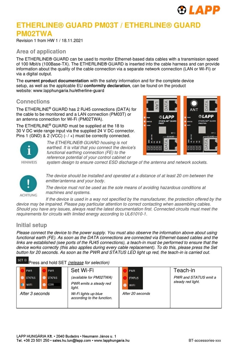
The ETHERLINE® GUARD has two RJ45 connections
(DATA) for the cable to be monitored and a LAN
connection (PM03T) or an antenna connection for WiFi
(PM02TWA) configuration via the web interface.
The LEDs on the left edge of the housing indicate the
status of the unit (PWR / STATUS / COM / WIFI) and the
status of the monitored data line.
Various functions can be carried out via the function button
(SET).
Application example:

ETHERLINE® GUARD | Issue 1e | 11.04.2022 13
4.1 Connection of the power supply
The ETHERLINE GUARD has to be connected with 24 V DC at the wide-
range input "18 ... 30 V DC" and "GND". The "FE" connection is for the
functional earth. Connect this properly to the reference potential.
The housing of the ETHERLINE® GUARD is not earthed.
Please be sure to connect the functional earth connection ("FE") of the unit to the reference potential of
your control cabinet or system structure to ensure correct ESD discharge of the antenna and network
sockets.
If the unit is used in a manner not specified by the manufacturer, the protection provided by
the unit may be impaired. Pay particular attention to correct contacting when installing the cables. Always
refer to the current documentation first in case of problems. Connected circuits must comply with the
requirements for limited energy circuits according to UL61010-1.
4.2 Connection of the line to be monitored (DATA)
The ETHERLINE® GUARD has two RJ45 connections (DATA) for the link to be monitored, whereby the
cable to be monitored must be connected to the RJ45 connection marked DATA + GUARD. The
ETHERLINE® GUARD is looped into the cable to be monitored via these two connections.
The cable to be monitored (e.g. a trailing cable) must be connected to the lower connection ("Guard").
The upper DATA port should then be connected to the communication partner (e.g. the control unit) with
another commercially available industrial Ethernet cable.
The cable measurement is carried out at the lower connection "Guard DATA" over the entire cable
(minimum length 2m) to the connected communication partner.
The ETHERLINE® GUARD does not change the content of the data transmission between the DATA
connections.
Data transmission between the two DATA connections only works when the ETHERLINE® GUARD is
supplied with voltage and is in normal operating mode!

ETHERLINE® GUARD | Issue 1e | 11.04.2022 14
4.3 Connecting the data connection (LAN / WIFI)
The data connection "LAN" (PM03T) or "WIFI" (PM02TWA) allows access to the web server of the
monitoring electronics via Ethernet line or via WiFi. The web page displays the status of the cable to be
monitored and enables configuration of the ETHERLINE® GUARD. Furthermore, the status of the cable
to be monitored can also be sent to databases or a cloud via MQTT.
For more information on how to access the website, see the chapter 6.
The use of the MQTT Publisher is explained in Chapter 8.
ETHERLINE® GUARD WIFI (PM02TWA)
The unit should be installed and operated with a minimum distance of 20 cm between the
radiator/antenna and your body. For information on the transmitting power, see the technical data in
chapter 12.2.
4.4 Connection of the digital outputs (Q1/Q2)
The digital outputs Q1 and Q2 are only active after the teach-in has been completed.
The digital output Q1 can signalize that maintenance is required for the cable if the value falls below a
configurable threshold ("Alarm threshold for Q1"). The default value is 80%. The output changes its
state to HIGH (normally open function) when it falls below this value. For more information on configuring
the threshold value, see chapter 7.1. If data communication is interrupted at the "Guard" connection,
output Q1 also changes its state to HIGH.
The digital output Q2 emits a pulse-width modulated signal whose duty cycle D is directly assigned to the
"Cable Status". The basic frequency is 24 Hz, the duty cycle varies from 99% (Cable Status = 100%) to
1% (Cable Status < 21%). If data communication is interrupted at the "Guard" connection, a duty cycle of
D = 1% is emitted.
A measured duty cycle of D % results in the following cable status (in %):
𝐶𝑎𝑏𝑙𝑒 𝑆𝑡𝑎𝑡𝑢𝑠 [%]=𝐷[%]
1.24 +20

ETHERLINE® GUARD | Issue 1e | 11.04.2022 15
4.5 Using the microSD card
A microSD card can be inserted into the left side of the housing. This card can record data for the
diagnosis of the unit and the measurement. The microSD card is not necessary for normal operation of
the unit! The measurement recordings can be used by the LAPP Support to analyse the unit.
If there is an SD card in the unit, the cable readings are automatically stored there.
Logging = off: Only the cable-specific measured values are saved on the card
Logging = on: In addition to the measured values, internal device data is stored (recommended).
When using an SD card, we recommend activating logging in order to have access to more diagnostic
data in case of an evaluation.

ETHERLINE® GUARD | Issue 1e | 11.04.2022 16
5 First commissioning ("teach-in")
The Ethernet data line to be monitored is connected to the lower DATA socket (GUARD). The upper
DATA socket is for the connection to the communication partner. A commercially available Ethernet data
line suitable for industrial use can be used here.
After the two DATA sockets have been connected via Ethernet lines and the Ethernet links of the
communication connection have been recognised (the other end of each cable is also connected), a
teach-in must be carried out once for the unit to work correctly.
A correct communication connection between the two communication partners can be recognised by the
LEDs of the DATA RJ45 sockets. If the green LED lights up at both RJ45 sockets, the Ethernet
connection is established. The flashing yellow LED at the RJ45 sockets indicates active data
transmission.
During the following teach-in procedure, the cable connected to DATA GUARD is now calibrated up to the
communication partner.
To start the teach-in process, please press the SET button for at least 20s. As soon as the PWR LED and
the STATUS LED both light up red simultaneously, release the SET button again.
after 20s
Teach-in
PWR and STATUS light up permanently red.
•All measurement data (cable status, teach-in values) are deleted.
•The teach-in is carried out.
•Other settings (network, MQTT, digital outputs) are retained.
•WiFi Access Point remains activated/deactivated according to the initial position.
•The LEDs switch off after releasing the SET button, the selected function is executed.
The calibration of the data line is now carried out during operation. This is indicated by a green flashing
STATUS LED. During this process, there may be brief interruptions in the data connection at the
respective link partners.
Teach-in / initialisation
PWR lights up permanently green.
STATUS flashes green (approx. 2Hz, duration approx. 1min.).
•Teach-in or initialisation in progress.
•After successful completion, change to operating state Ready for operation.
Faulty teach-in
PWR flashes alternately red/green (approx. 2Hz, duration unlimited
until a factory reset or teach-in is carried out).
•Teach-in could not be executed.
•Check wiring and earthing concept if necessary.
•Then carry out the teach-in again.

ETHERLINE® GUARD | Issue 1e | 11.04.2022 17
No teach-in carried out
PWR lights up permanently green.
•No teach-in has been carried out.
•Cable status is neither determined nor output.
•Perform teach-in.
When the teach-in process is complete, the PWR LED and the STATUS LED should light up green
continuously.
Ready for operation
PWR and STATUS light up permanently green. WiFi blue, green or
alternating according to the operating status.
•ETHERLINE GUARD is in normal operation.
•Monitored line OK.
Cable condition > set alarm threshold (default = 80%)
•Digital outputs switch depending on configuration (Q1 = NO "low", Q2 = PWM)
•WiFi
oBlue = Access point active
oGreen = Client active
oGreen flashing (1Hz) = Device is trying to establish a connection to an access point
oBlue and green alternately (every 3s) = Access point and client active
If an error occurs during the teach-in process, the PWR LED flashes green/red.
The teach-in procedure must be repeated after each cable exchange!
The teach-in values are permanently stored in the unit and are retained even in the event of a power
failure or a firmware update (software update).
The ETHERLINE® GUARD is now in measuring and monitoring mode. The status of the cable is
indicated via the STATUS LED, the web interface and by the two outputs Q1 & Q2. In addition, the cable
status can be sent via MQTT.
If the STATUS LED lights up or flashes red, the measurement has shown that the electrical characteristic
values of the cable have deteriorated and the monitoring threshold value has been undercut.
Replacement is advisable (soon).

ETHERLINE® GUARD | Issue 1e | 11.04.2022 18
Maintenance required
PWR lights up permanently green.
STATUS flashes red (approx. 1Hz).
•ETHERLINE GUARD is in normal operation.
•Maintenance of the monitored cable necessary
Set alarm threshold (default = 80%) > Cable condition > 20%
•Digital outputs switch depending on configuration (Q1 = "high", Q2 = PWM)
Line defective
PWR lights up permanently green.
STATUS lights up permanently red
•ETHERLINE GUARD is in normal operation.
•Monitored line is defective: Cable condition < 20% or
•Monitored line is not connected.
•Digital outputs switch as follows (Q1 = "high", Q2 = PWM, D = 0.01)
If the ETHERLINE® GUARD is restarted after a successful teach-in or if there was a power failure, the
measurement requires a few seconds until a measured value is available again.
This is indicated after the restart by a green flashing STATUS LED (initialisation).
after 10s
Soft reset
PWR lights up permanently green.
STATUS lights up permanently red
•The unit is restarted and the data traffic is briefly interrupted.
•All parameters are retained.
•WiFi Access point remains activated/deactivated according to the initial position.
•The LEDs go out after releasing the set button, the selected function is executed.
after 25s
Demolition
PWR lights up permanently green.
•WiFi access point, soft reset and teach-in are cancelled.
•WiFi Access point remains activated/deactivated according to the initial position.
•The LEDs switch off after releasing the set button, the selected function is executed.

ETHERLINE® GUARD | Issue 1e | 11.04.2022 19
6 Access to the web interface
The web page for displaying the cable status and configuring the ETHERLINE® GUARD can be
accessed via the "LAN" interface (PM03T) or via WIFI (PM02TWA).
The ETHERLINE® GUARD website has a default IP address when delivered and after a factory reset.
This is printed on the right-hand side of the unit.
For the ETHERLINE® GUARD version "LAN" it is the IP address 192.168.0.32
For the ETHERLINE® GUARD version "WIFI" it is the IP address 192.168.4.1
For optimal use and display, Lapp recommends using Google Chrome as your browser.
6.1 Access via LAN
Connect the LAN interface of the ETHERLINE® GUARD to your PC via a standard Ethernet cable. The
LAN interface supports 10 and 100 Mbit/s. When accessing the website for the first time, set your PC
interface to the appropriate subnet, e.g. with the IP address 192.168.0.1 with subnet mask 255.255.255.0
for LAN access.
Open the website in a current browser with https://192.168.0.32.
For security reasons, the web interface can only be accessed via a secure HTTPS connection. To reach
the website, an exception rule may have to be confirmed in the browser.
If required, a separate certificate for the connection protection can be stored in the "Settings" menu.
Further information on how to handle and set up certificates can be found on the ETHERLINE® GUARD
homepage.
6.2 Access via WIFI
The ETHERLINE® GUARD with WiFi activates its own access point (AP) with the SSID name
"LAPP_xxxxxxxx" in the factory state. The unique device SSID can be read on the right side panel of the
device. The default WiFi password is "12345678".
As soon as you have established the connection with the WLAN network of the ETHERLINE® GUARD,
the web interface can be accessed in the browser at https://192.168.4.1.
If the ETHERLINE® GUARD is to be integrated into an existing WLAN, it can be switched to client
operation. Information on WiFi configuration can be found in chapter 7.3.

ETHERLINE® GUARD | Issue 1e | 11.04.2022 20
after 3s
WiFi Access point
(available at PM02TWA)
PWR lights up permanently red.
WiFi lights up blue according to the function.
•Deactivation/activation of the WiFi access point depending on the initial situation.
•The LEDs switch off after releasing the set button, the selected function is executed.
6.3 Initial registration
When logging in for the first time, you will be asked to set a password for the default user "admin". The
password must be at least 8 characters long.
Please memorise the password well! For security reasons, there is no way to reset the password without
resetting the unit to factory settings.
Other manuals for ETHERLINE GUARD PM03T
3
This manual suits for next models
1
Table of contents
Other LAPP Network Hardware manuals
Popular Network Hardware manuals by other brands

MikroTik
MikroTik G16-a-LHGR kit Series quick guide

Alcatel-Lucent
Alcatel-Lucent VitalQIP 500 Specifications

Provision ISR
Provision ISR IP Series user manual

Johnson Controls
Johnson Controls CK722 manual

IBM
IBM 084 Installation and user guide

ProfiTap
ProfiTap PROFISHARK 1G+ Installation and configuration manual