CargoBrite CB-KITSTD2 User manual

Step-By-Step Installation Guide
2-LEDS (CB-KITSTD2) & 4-LEDS (CB-KITSTD4) KITS
NOTE: PLEASE READ ALL STEPS BEFORE BEGINNING INSTALLATION. 2-LED Kit recommended for trailers
less than 28’ in length. 4-LED Kit recommended for trailers 53’ in length. MUST BE INSTALLED BY QUALIFIED
ELECTRICAL INSTALLER.
Safety Equipment
• Gloves • Safety Glasses
Tools Needed
• Wire Strippers
• Wire Crimpers
• 5/16” Socket
• ¼” Socket
• Impact Driver
• Step Ladder
• Hammer
• Plyers
Included in Kit
ITEM CB-KITSTD2 CB-KITSTD4
CargoBrite LED Single End (TYPE 1) 1 2
CargoBrite LED Double End (TYPE 2) 1 2
Bullet Connectors (Male & Female Set) 15 20
Push Button On/Off Switch 1 1
Fuse Holder w/ Fuse 1 1
18 AWG Red & Black Wire 35’ 60’
Mounting Brackets for LED 4 8
Solderless Wire Connectors 2 4
Switch Mounting Bracket 1 1
Push On Wire Management Clips 20 30
Screw Wire Management Clips 6 6
Screws for Switch Bracket, Wire Clips 7 7

Step-By-Step Installation Guide
Trailer Mounting Layout
53’ TRAILER Recommended Layout Mounting LEDs
28’ TRAILER Recommended Layout Mounting LEDs
Red Line Indicates Wire Path
LED Type 1 = CargoBrite Double End LED
LED Type 2 = CargoBrite Single End LED
Dimensions are an approximation. Not exact values.
53'
13'
13'
8' FROM END
13' FROM DOOR
28'
8' FROM DOOR
6' FROM END
REVISIONS
1 OF 1
REV
SIZE
XXXXXXXX
REV
SHEET
FINISH
A
XXXXXXX
APPROVED
Description
MATERIAL
DO NOT SCALE
A
DESCRIPTION
XXXXXX
MOUNTING LAYOUT 28 AND 53 FEET TRAILERS
SCALE
DATE
DWG NO.
BACK
FRONT
POWER TO LICENSE PLATE
TOP VIEW OF TRAILER
53' TRAILER RECOMMENDED LAYOUT MOUNTING LEDs
28' TRAILER RECOMMENDED LAYOUT MOUNTING LEDs
TOP VIEW OF TRAILER
FRONT
BACK
POWER TO LICENSE PLATE
LED TYPE 1
LED TYPE 1
LED TYPE 2
LED TYPE 2
LED TYPE 2
LED TYPE 2
DIMENSIONS ARE APPROXIMATIONS,
NOT EXACT VALUES.
LED TYPE 1 = CARGOBRITE DOUBLE END LED
LED TYPE 2 = CARGOBRITE SINGLE END LED
RED LINE INDICATES WIRE PATH

Step-By-Step Installation Guide
Simplistic Wiring Schematic
The following schematic is a simplified version of the actual circuit. Use this as a tool on how the connections
need to be made.
NOTE: Variance from this schematic may result in light failure, blown fuses resulting in damage to exterior
marker lights, etc.
REV
DWG NO.
FINISH
1 OF 1
DATE
A
DO NOT SCALE
A
SHEET
SIZE
MATERIAL
XXXXXXX
XXXXXX
SCALE
XXX
REVISIONS
XXXXXXXX
APPROVED
REV
DESCRIPTION
Description
LED TYPE 2LED TYPE 1
SWITCH
FUSE
FURTHEST FROM POWER
CLOSEST TO POWER
- FEMALE CONNECTOR
ON RED WIRE
STANDARD PRACTICE CONNECTOR ORIENTATION
LED TYPE 2
LED TYPE 2
LED TYPE 1
LED TYPE 1
SWITCH
FUSE
+12V POWER
NEGATIVE OR
TRAILER GROUND
+12V POWER
NEGATIVE OR
TRAILER GROUND
NOTE: BLACK WIRE RUNS
DIRECTLY FROM BLACK
T-CONNECTOR WIRE TO
GROUND/NEGATIVE
NOTE: BLACK WIRE RUNS
DIRECTLY FROM LED TO
GROUND/NEGATIVE
2 - LIGHT KIT
4 - LIGHT KIT
SPLICE
CONNECTOR
SPLICE
CONNECTOR
REV
DWG NO.
FINISH
1 OF 1
DATE
A
DO NOT SCALE
A
SHEET
SIZE
MATERIAL
XXXXXXX
XXXXXX
SCALE
XXX
REVISIONS
XXXXXXXX
APPROVED
REV
DESCRIPTION
Description
LED TYPE 2LED TYPE 1
SWITCH
FUSE
FURTHEST FROM POWER
CLOSEST TO POWER
- FEMALE CONNECTOR
ON RED WIRE
STANDARD PRACTICE CONNECTOR ORIENTATION
LED TYPE 2
LED TYPE 2
LED TYPE 1
LED TYPE 1
SWITCH
FUSE
+12V POWER
NEGATIVE OR
TRAILER GROUND
+12V POWER
NEGATIVE OR
TRAILER GROUND
NOTE: BLACK WIRE RUNS
DIRECTLY FROM BLACK
T-CONNECTOR WIRE TO
GROUND/NEGATIVE
NOTE: BLACK WIRE RUNS
DIRECTLY FROM LED TO
GROUND/NEGATIVE
2 - LIGHT KIT
4 - LIGHT KIT
SPLICE
CONNECTOR
SPLICE
CONNECTOR

Step-By-Step Installation Guide
STEP 1: Locate Power +12V, Splice Connector
Locate 12V power source by finding the wires supplying the trailers exterior marker lights. Not all trailers will
have the same 12V power source. In some cases, the Ground Wire will need to connect to the trailer frame.
How To Use Splice Connector
1. Align Red Wire with 12V Power Source.
2. Use plyers to pinch down metal continuity connector.
3. Apply Dielectric Grease to prevent corrosion.
4. Close Latch
Repeat with the negative or ground wire from trailer with
black wire.

Step-By-Step Installation Guide
STEP 2: Organizing Exterior Wire from Power Source
Using zip ties and supplied mounting clips attach wire to frame ensuring that the wire is not free to move
around or loose to help prevent damage to exterior wire.
WARNING: LOOSE WIRES CAN RESULT IN DAMAGE TO CARGOBRITE SYSTEM OR EXTERIOR MARKER
LIGHTS OF TRAILER.

Step-By-Step Installation Guide
STEP 3: Run Wire from Exterior Power to Inside of Trailer
Find a spot to feed the wire from the exterior to the interior near the back of the trailer. If you cannot
find a way inside the trailer, drill a ¼” hole through the bottom of the trailer near the power source close to
the side wall. Feed wire through hole. Once fed completely through, caulk hole with silicon or another type
of protection.
WARNING: CHECK TO SEE IF WIRE IS RUBBING ON SURFACE. THIS CAN RESULT IN ACCELERATED WEAR OF
WIRE WHICH CAN CAUSE FAILURE.

Step-By-Step Installation Guide
STEP 4: Mount LED Lights to Trailer
Using the supplied brackets, 2 per light, locate the best mounting locations for LEDs. The Recommended
mounting layout should be referenced to best maximize spread of light. Lights with only one wire end
will be placed furthest into trailer. Once you have located the position you would like to mount the LEDs,
position the brackets approximately 6” from the end of the LED. IMPORTANT: WHEN APPLYING BRACKET
SCREW ENSURE THAT THE HOLE IS NOT GOING TO PUNCTURE THE ROOF. Using 5/16” socket drive screw
into sheet metal with impact driver.
WARNING: CHECK TO SEE IF WIRE IS RUBBING ON SURFACE. THIS CAN RESULT IN ACCELERATED WEAR OF
WIRE WHICH CAN CAUSE FAILURE.

Step-By-Step Installation Guide
STEP 5: Connecting LEDs in Series Using Supplied Wire
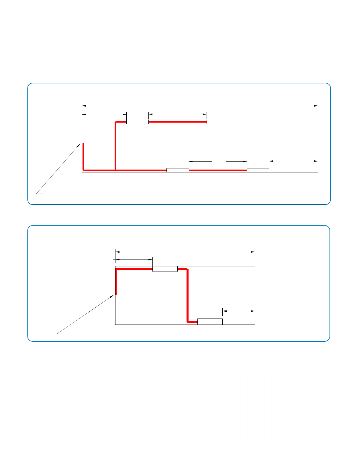
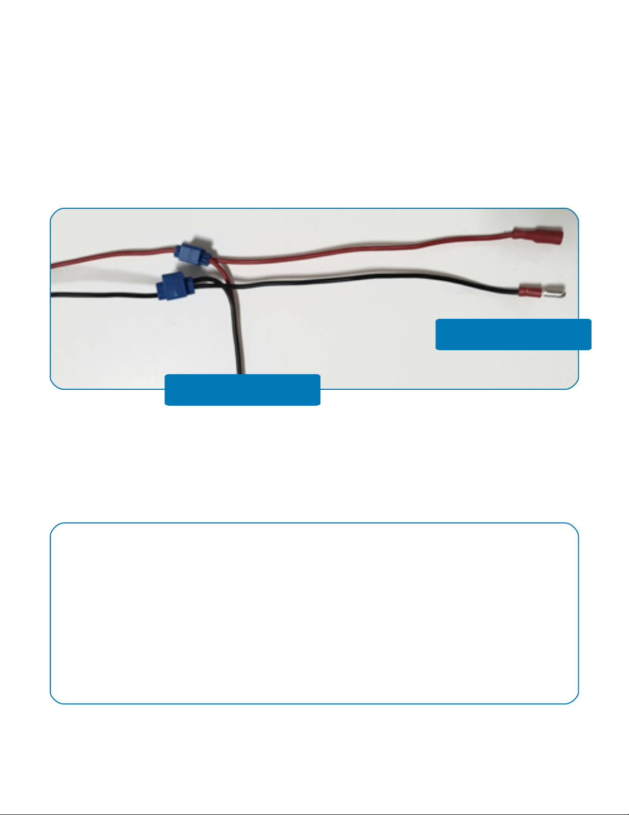
Connect LEDs with wire. Cut the appropriate length to reach the other LED leads. Please refer to mounting
layout/electrical schematic. Red wire runs to red wire and black wire to black wire. NOTE: APPLY A FEMALE
BULLET CONNECTOR TO THE RED WIRE THAT WILL BE CLOSEST TO POWER ALWAYS. THIS WILL PREVENT
POWER FROM GROUNDING OUT ON TRAILER.
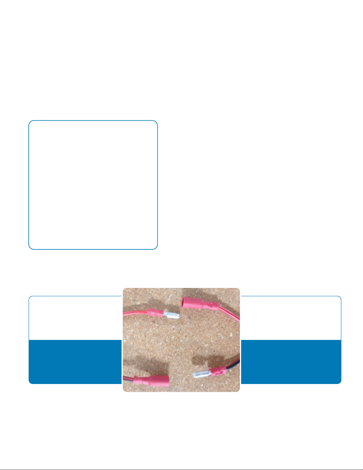
How To Use Bullet Connectors
1. Strip wire back ¼” for each connector that needs to be
applied.
2. Slide the required bullet connector over.
3. Crimp bullet connector to wire. Ensure that Bullet
Connector has a good hold by tugging on the connector.
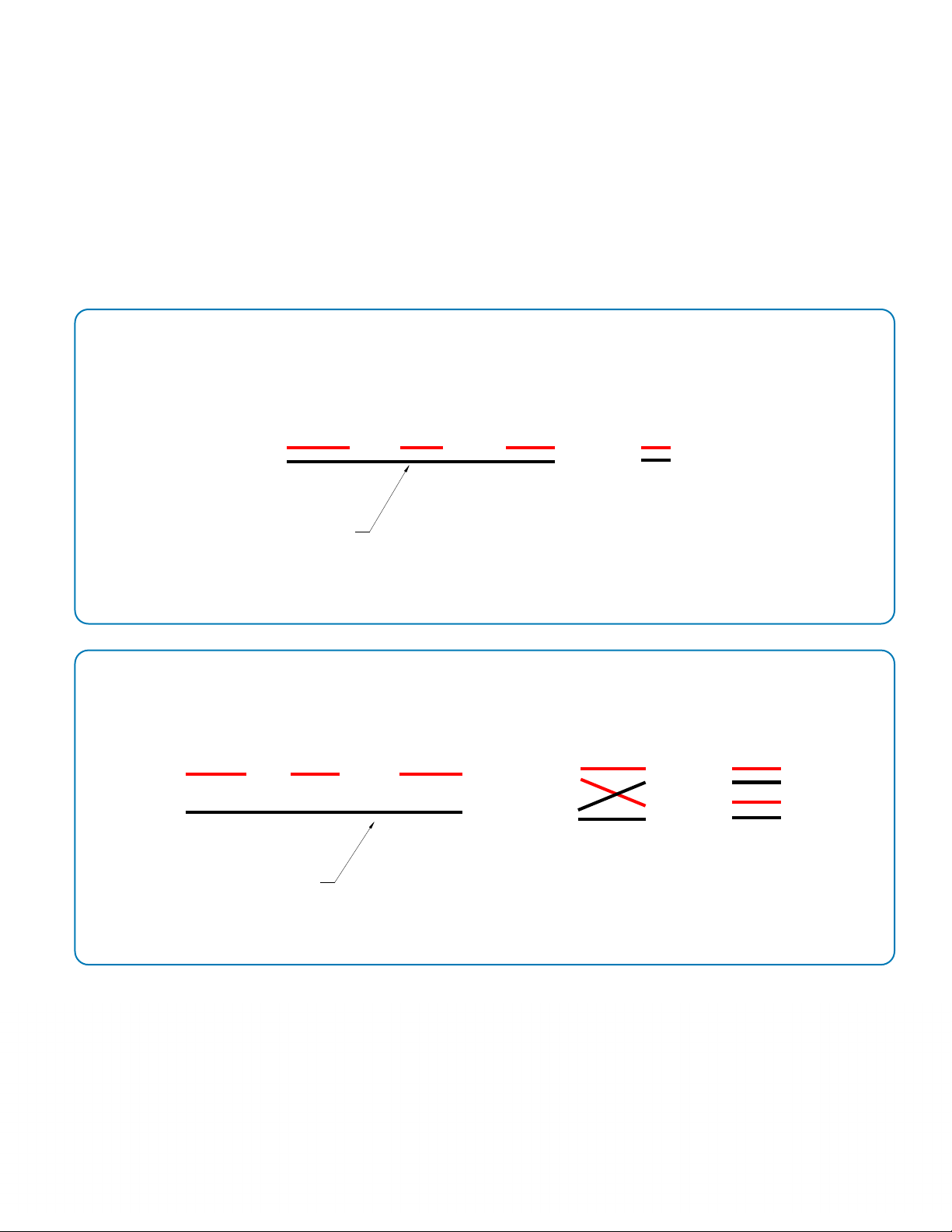
Red wire closest to power
Female connector (+12 volt)
Black wire closest to power
Male connector (+12 volt)
Red wire furthest from power
Male connector
Black wire furthest from power
Female connector
Standard Practice Between All Connections

Step-By-Step Installation Guide
STEP 6: Solderless Wire Splice Connectors (only for 4 - Light Kit)
If you are installing a 4 light kit you will be needing 2 Splice Connectors to turn two LED Leads into 1.
Please reference the diagram for Electrical Schematic 4 Light Kit to see how the wire is aligned in the Splice
Connector. If you do not need a Splice Connector, 2 LED kit set, run black ground/negative wire directly to
grounding point. Apply solderless splice connectors to the closest LED to the switch.
Connects to other side LEDs
Connects to +12 volt power
STEP 7: On/Off Switch
Find a suitable location for the switch and use switch mounting bracket to fix to wall. CAUTION: LOCATE
SWITCH TO AREA THAT WILL NOT BE DAMAGED BY FREIGHT. Run RED Wire from LEDs or T-Connector to the
Switch. Again, female bullet connector needs to be used closest to power source.

Step-By-Step Installation Guide
STEP 8: Fuse
Using bullet connectors connect fuse holder to the on/off switch. Remove the fuse from the holder until the
instillation is complete. Again, Female Connector needs to be used closest to Power Source.
STEP 9: Wiring to Power
Run Red Wire from the fuse to the +12V power. This wire should already be fed to the interior of the trailer.
CAUTION: ENSURE THAT THE COMPLETE WIRE SYSTEM HAS ONLY RED WIRE TO RED WIRE AND BLACK
WIRE TO BLACK WIRE (EXEMPTION SWITCH WIRE IS BLACK SO WILL HAVE RED WIRE FROM FUSE AND
LEDs. IF YOU FIND A WIRE THAT DOES NOT FIT THIS CIRCUMSTANCE, FIX IMMEDIATELY TO ENSURE CIRCUIT
IS CORRECT. NOT FOLLOWING COULD RESULT IN A BLOWN FUSE FOR OTHER EXTERIOR LIGHTS.

Step-By-Step Installation Guide
STEP 10: Apply Wire Clips
Apply Wire Management Clips using a hammer to hold the wire up and out of the way. Ensure each clip
has a good hold to mating surface. Wire Running across the trailer may need to be held with white wire
management clips.
WARNING: LOOSE CLIPS COULD RESULT IN DROOPING WIRES IF THEY ARE REMOVED. IF CLIP APPEARS
LOOSE TIGHTEN BY PINCHING CLIP.

Step-By-Step Installation Guide
STEP 11: Final Inspection
•Verify all wires are secured/tucked away
•Bullet connectors have tight connection
• Wiring matches electrical schematic
• Switch cannot be hit by freight
If the installation passes final inspection insert 5-amp fuse and proceed to turn lights on with on/off switch.
Verify that there is no flickering of the lights and functionality of exterior lights is correct. If lights are not
functioning correctly verify that fuses, electrical circuit are correct.
28’ Trailer 53’ Trailer, Person at 40’
This manual suits for next models
1
Table of contents