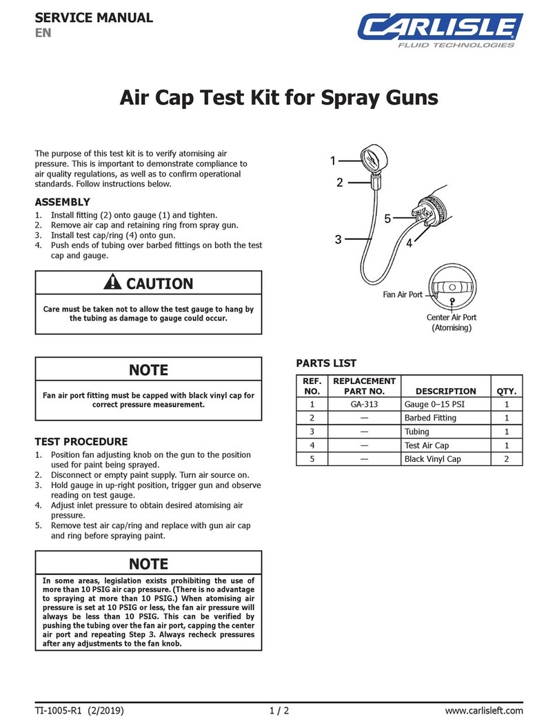
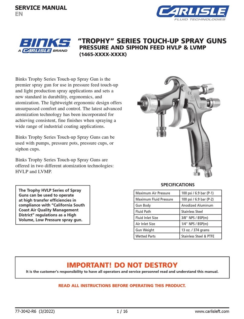
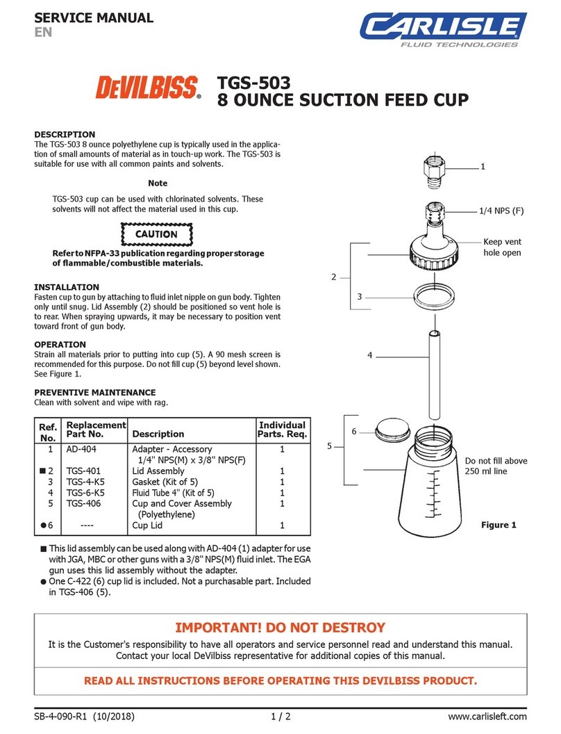
Carlisle Fluid Technologies Ransburg RansFlex 85 User manual

EN
SERVICE MANUAL
AH-21-01-R4 (02/2022) 1 / 60 www.carlisleft.com
RansFlex Applicators - Air Assist
Model 80885
xxxx
xxxx

MANUAL CHANGES EN
AH-21-01-R4 (02/2022) 2 / 60 www.carlisleft.com
NOTE: This manual has been changed from revision AH-21-01-R3 to revision
AH-21-02-R4.Reasonsforthischangearenotedunder“ManualChange
Summary” inside the back cover of this manual.

CONTENTS
EN
AH-21-01-R4 (02/2022)3 / 60www.carlisleft.com
CONTENTS
SAFETY: 4-8
Safety Precautions ........................................................................................................................................................4
Hazards / Safeguards ....................................................................................................................................................5
ATEX/FM/UKEX: 9-13
European ATEX Directive ..............................................................................................................................................9
Labels ..........................................................................................................................................................................10
RansexRXSolventBaseConguration....................................................................................................................11
INTRODUCTION: 14-17
General Description .....................................................................................................................................................14
RansFlexNewFeatures..............................................................................................................................................14
Specications ..............................................................................................................................................................15
Typical Installation .......................................................................................................................................................16
RansFlexSolventborneElectrostaticSprayApplicator ...............................................................................................17
INSTALLATION: 18-20
80885RansFlexAirAssistInstallation ........................................................................................................................18
General Installation Requirements ..............................................................................................................................18
Installation ...................................................................................................................................................................19
OPERATION: 21-25
Applicator Operation ....................................................................................................................................................21
Flushing/Color Change Procedure ..............................................................................................................................23
Fluid Tips .....................................................................................................................................................................24
Trigger Lock Feature ...................................................................................................................................................25
MAINTENANCE: 26-41
SuitableSolventforCleaningRansFlexApplicators ...................................................................................................26
Routine Schedule ........................................................................................................................................................27
Troubleshooting Guide ................................................................................................................................................41
PARTS IDENTIFICATION: 42-58
RansFlexRX-SolventBase.......................................................................................................................................42
Retaining Ring / Air Cap Assembly ..............................................................................................................................45
NeedleShaftAssembly ...............................................................................................................................................46
AABarrel/Cascade ....................................................................................................................................................47
Handle Components for AA Models ............................................................................................................................48
HandlewithRearCoverwithMotor.............................................................................................................................50
Handle Assembly .........................................................................................................................................................51
Rear Cartridge Assembly / Fan Air Cartridge ..............................................................................................................52
RearCoverwithMotorAssembly .................................................................................................................................53
Motor Assembly............................................................................................................................................................54
Rear Cover Assembly...................................................................................................................................................55
Accessories..................................................................................................................................................................56
Spare Parts ..................................................................................................................................................................57
MANUAL CHANGE SUMMARY: 59
Manual Changes .........................................................................................................................................................59

SAFETY EN
AH-21-01-R4 (02/2022) 4 / 60 www.carlisleft.com
CAUTION
!
WARNING
!
NOTE
SAFETY PRECAUTIONS
Beforeoperating,maintainingorservicingany
electrostatic
coating system
, read and understand all of the technical
and safety literature for your products. This manual contains
informationthatisimportantforyoutoknowandunderstand.
ThisinformationrelatestoUSERSAFETYandPREVENTING
EQUIPMENT PROBLEMS. To help you recognize this
information, we use the following symbols. Please pay
particular attention to these sections.
A WARNING! states information to alert you to
a situation that might cause serious injury if
instructions are not followed.
A CAUTION! states information that tells how to
prevent damage to equipment or how to avoid a
situation that might cause minor injury.
A NOTE is information relevant to the procedure
in progress.
Whilethismanuallistsstandardspecicationsandservice
procedures,someminordeviationsmaybefoundbetween
thisliteratureandyourequipment.Differencesinlocalcodes
andplantrequirements,materialdeliveryrequirements,etc.,
makesuchvariationsinevitable.Comparethismanualwith
yoursysteminstallationdrawingsandassociatedequipment
manuals to reconcile such differences.
WARNING
!
WARNING
!
The user MUSTreadandbefamiliarwiththe
Safety Section in this manual and the safety literature
thereinidentied.
This equipment is intended to be used by
trained personnel ONLY.
This manual MUST be read and thoroughly
understood by ALL personnel who operate, clean
or maintain this equipment! Special care should
be taken to ensure that the WARNINGS and safety
requirements for operating and servicing the
equipment are followed. The user should be aware
of and adhere to ALL local building and re codes
andordinancesaswellas NFPA 33 AND EN 16985
SAFETY STANDARDS, LATEST EDITION, or
applicablecountrysafetystandards,priortoinstalling,
operating,and/orservicingthisequipment.
The hazards shown on the following pages may
occur during the normal use of this equipment.
SAFETY
Repairs may only be performed by personnel authorized by
Carlisle Fluid Technologies.
Carefulstudyandcontinueduseofthismanualwillprovidea
betterunderstandingoftheequipmentandprocess,resulting
inmoreefcientoperation,longertrouble-freeserviceand
faster,easiertroubleshooting.Ifyoudonothavethemanuals
andsafetyliteratureforyourequipment,contactyourlocal
Carlisle Fluid Technologies representative or Carlisle Fluid
Technologies technical support.

SAFETY
EN
AH-21-01-R4 (02/2022)5 / 60www.carlisleft.com
AREA
Tellswherehazards
may occur.
HAZARD
Tellswhatthehazardis.
SAFEGUARDS
Tellshowtoavoidthehazard.
Spray Area Fire Hazard
Improper or inadequate
operation and maintenance
procedureswillcauseare
hazard.
Protection against inadvertent
arcing that is capable of
causingreorexplosionislost
if any safety interlocks are
disabled during operation.
FrequentPowerSupplyor
Controllershutdownindicates
a problem in the system
requiring correction.
Fireextinguishingequipmentmustbepresentinthe
spray area and tested periodically.
Spray areas must be kept clean to prevent the
accumulation of combustible residues.
Smokingmustneverbeallowedinthesprayarea.
The high voltage supplied to the atomizer must be
turnedoffpriortocleaning,ushing,ormaintenance.
Spray booth ventilation must be kept at the rates
requiredbyNFPA33,EN16985,country,andlocal
codes.Inaddition,ventilationmustbemaintained
duringcleaningoperationsusingammableor
combustible solvents.
Electrostatic arcing must be prevented. Safe
sparkingdistancemustbemaintainedbetweenthe
parts being coated and the applicator. A distance of
1 inch for every 10KV of output voltage is required
at all times.
Test only in areas free of combustible material.
Testingmayrequirehighvoltagetobeon,butonly
as instructed.
Non-factoryreplacementpartsorunauthorized
equipmentmodicationsmaycausereorinjury.
Ifused,thekeyswitchbypassisintendedforuse
only during setup operations. Production should
neverbedonewithsafetyinterlocksdisabled.
The paint process and equipment should be set up
andoperatedinaccordancewithNFPA33,NEC,
OSHA,local,country,andEuropeanHealthand
SafetyNorms.

SAFETY EN
AH-21-01-R4 (02/2022) 6 / 60 www.carlisleft.com
AREA
Tellswherehazards
may occur.
HAZARD
Tellswhatthehazardis.
SAFEGUARDS
Tellshowtoavoidthehazard.
Improper or inadequate
operation and maintenance
procedureswillcausea
rehazard.
Protection against inadvertent
arcing that is capable of
causingreorexplosionislost
if any safety interlocks are
disabled during operation.
FrequentPowerSupplyor
Controllershutdownindicates
a problem in the system
requiring correction.
Improper operation or
maintenance may create
a hazard.
Personnel must be properly
trained in the use of this
equipment.
Personnelmustbegiventraininginaccordancewith
therequirementsofNFPA33.
Instructions and safety precautions must be read and
understood prior to using this equipment.
Complywithappropriatelocal,state,andnational
codesgoverningventilation,reprotection,operation
maintenance,andhousekeeping.ReferenceOSHA,
NFPA33,ENNormsandyourinsurancecompany
requirements.
General Use and
Maintenance
Spray Area Explosion Hazard
Electrostatic arcing must be prevented. Safe sparking
distancemustbemaintainedbetweenthepartsbeing
coated and the applicator. A distance of 1 inch for
every 10KV of output voltage is required at all times.
Unlessspecicallyapprovedforuseinhazardous
locations,allelectricalequipmentmustbelocated
outsideClassIorII,Division1or2hazardousareas,
inaccordancewithNFPA33.
Testonlyinareasfreeofammableorcombustible
materials.
The current overload sensitivity (if equipped)
MUST be set as described in the corresponding
section of the equipment manual. Protection against
inadvertentarcingthatiscapableofcausingre
orexplosionislostifthecurrentoverloadsensitivity
isnotproperlyset.Frequentpowersupply
shutdownindicatesaprobleminthesystemwhich
requires correction.
Alwaysturnthecontrolpanelpoweroffpriorto
ushing,cleaning,orworkingonspraysystem
equipment.
Beforeturninghighvoltageon,makesurenoobjects
arewithinthesafesparkingdistance.
Ensurethatthecontrolpanelisinterlockedwiththe
ventilationsystemandconveyorinaccordancewith
NFPA-33,EN16985.
Havereextinguishingequipmentreadilyavailable
and tested periodically.

SAFETY
EN
AH-21-01-R4 (02/2022)7 / 60www.carlisleft.com
AREA
Tellswherehazards
may occur.
HAZARD
Tellswhatthehazardis.
SAFEGUARDS
Tellshowtoavoidthehazard.
Spray Area /
High Voltage
Equipment
There is a high voltage device
that can induce an electrical
chargeonungroundedobjects
whichiscapableofigniting
coating materials.
Inadequategroundingwill
cause a spark hazard. A
spark can ignite many coating
materialsandcauseare
orexplosion.
Electrical Discharge
Parts being sprayed and operators in the spray
area must be properly grounded.
Parts being sprayed must be supported on
conveyors or hangers that are properly grounded.
Theresistancebetweenthepartandearthground
mustnotexceed1MegOhm.(RefertoNFPA33,
EN16985.)
Operators must be grounded. Rubber soled
insulatingshoesshouldnotbeworn.Grounding
strapsonwristsorlegsmaybeusedtoassure
adequate ground contact.
Operatorsmustnotbewearingorcarryingany
ungroundedmetalobjects.
Whenusinganelectrostatichandgun,operators
mustassurecontactwiththehandleoftheapplicator
viaconductiveglovesorgloveswiththepalmsection
cut out.
NOTE:REFERTONFPA33,EN16985OR
SPECIFICCOUNTRYSAFETYCODES
REGARDINGPROPEROPERATOR
GROUNDING.
Allelectricallyconductiveobjectsinthesprayarea,
withtheexceptionofthoseobjectsrequiredbythe
processtobeathighvoltage,mustbegrounded.
Groundedconductiveooringmustbeprovidedin
the spray area.
Alwaysturnoffthepowersupplypriortoushing,
cleaning,orworkingonspraysystemequipment.
Unlessspecicallyapprovedforuseinhazardous
locations,allelectricalequipmentmustbelocated
outsideClassIorII,Division1or2hazardous
areas,inaccordancewithNFPA33.
Avoidinstallinganapplicatorintoauidsystem
wherethesolventsupplyisungrounded.
Donottouchtheapplicatorelectrodewhileitis
energized.

SAFETY EN
AH-21-01-R4 (02/2022) 8 / 60 www.carlisleft.com
AREA
Tellswherehazards
may occur.
HAZARD
Tellswhatthehazardis.
SAFEGUARDS
Tellshowtoavoidthehazard.
High voltage equipment is
utilized in the process. Arcing
inthevicinityofammableor
combustible materials may
occur.Personnelareexposed
to high voltage during
operation and maintenance.
Protection against inadvertent
arcingthatmaycauseareor
explosionislostifsafetycircuits
are disabled during operation.
Frequentpowersupplyshut-
downindicatesaproblemin
thesystemwhichrequires
correction.
An electrical arc can ignite
coating materials and cause a
reorexplosion.
Electrical DischargeElectrical
Equipment
Follow the requirements of the Safety Data Sheet
supplied by coating material manufacturer.
Adequate exhaust must be provided to keep the air
freeofaccumulationsoftoxicmaterials.ReferenceEN
12215 or applicable code.
Useamaskorrespiratorwheneverthereisachance
of inhaling sprayed materials. The mask must be
compatible with the material being sprayed and its
concentration. Equipment must be as prescribed
by an industrial hygienist or safety expert, and be
NIOSHapproved.
Chemical HazardToxic
Substances Certain materials may be
harmfulifinhaled,orifthere
iscontactwiththeskin.
Unless specically approved for use in hazardous
locations, the power supply, control cabinet, and all
other electrical equipment must be located outside
Class I or II, Division 1 and 2 hazardous areas in
accordancewithNFPA33andEN16985.
TurnthepowersupplyOFFbeforeworkingonthe
equipment.
Testonly inareas freeofammableor combustible
material.
Testing mayrequire highvoltage tobe on, butonly
as instructed.
Production should never be done with the safety
circuits disabled.
Before turning the high voltage on, make sure no
objectsarewithinthesparkingdistance.
Spray applicators require that aluminum inlet ttings
bereplacedwithstainlesssteel.
Aluminumiswidelyusedinothersprayapplication
equipment-suchasmaterialpumps,regulators,
triggeringvalves,etc.Halogenatedhydrocarbon
solventsmustneverbeusedwithaluminumequip-
mentduringspraying,ushing,orcleaning.Read
the label or data sheet for the material you intend to
spray.Ifindoubtastowhetherornotacoatingor
cleaningmaterialiscompatible,contactyourcoating
supplier.Anyothertypeofsolventmaybeusedwith
aluminum equipment.
Halogenated hydrocarbon
solventsforexample:
methylenechlorideand1,1,1,
-Trichloroethanearenot
chemicallycompatiblewiththe
aluminum that might be used
in many system components.
The chemical reaction caused
bythesesolventsreactingwith
aluminum can become violent
and lead to an equipment
explosion.
Explosion Hazard —
Incompatible Materials
Spray Area

ATEX/FM/UKEX
EN
AH-21-01-R4 (02/2022)9 / 60www.carlisleft.com
ATEX /FM/ UKEX
Thefollowinginstructionsapplytoequipmentcoveredby
certicatenumberFM21ATEX0045,FM21UKEX0166:
1. Theequipmentmaybeusedwithammablegasesand
vaporswithapparatusgroupsIIandwithtemperature
class T6.
2.
The equipment is only certied for use in ambient
temperatures in the range 5°C to +40°C and should not
be used outside this range.
3.
Installationshallbecarriedoutbysuitablytrainedpersonnel
inaccordancewiththeapplicablecodeofpracticee.g.
EN60079-14.
4. Inspectionandmaintenance ofthisequipment shallbe
carriedoutbysuitablytrained personnelinaccordance
withtheapplicablecodeofpracticee.g.EN60079-17.
5.
Repair of this equipment shall be carried out by
suitabletrainedpersonnelinaccordancewiththe
applicablecodeofpracticee.g.EN60079-19.
6. Puttingintoservice,use,assembling,andadjustment
of the equipment shall be tted by suitably trained
personnel in accordance with the manufacturer's
documentation.
Refertothe"TableofContents"ofthisservice manual:
a. Installation
b. Operation
c. Maintenance
d.PartsIdentication
7. Components to be incorporated into or used as
replacement parts of the equipment shall be tted
bysuitablytrainedpersonnelinaccordancewiththe
manufacturer'sdocumentation.
8. The certication of this equipment relies upon the
followingmaterialsusedinitsconstruction:
Referto“Specications”inthe“Introduction”section:
a. Alluidpassagescontainstainlesssteel,peek
nylon.
b. Highvoltagecascadeisencapsulatedwithasolvent
resistantepoxy.
c. Nylons,AcetalResins
d. Stainless Steel
e. PTFE Materials
Iftheequipment islikelytocomeintocontactwith
aggressivesubstances,then it istheresponsibility
of the user to take suitable precautions that prevent
itfrombeingadverselyaffected,thusensuringthat
the type of protection provided by the equipment is
not compromised.
Aggressive substances: e.g. acidic liquids or gases
that may attack metals, or solvents that may affect
polymeric materials.
Suitable precautions: e.g. regular checks as part of
routineinspectionsorestablishingfromthematerial's
datasheetsthatitisresistanttospecicchemicals.
9. Arecapitulationofthecerticationmarkingisdetailed
in the "ATEX" section, on the next page, drawing
numbers: 80886.
10.
Thecharacteristicsoftheequipment shallbedetailed
e.g.electrical,pressure,andvoltageparameters.
The manufacturer should note that, on being put into
service, the equipment must be accompanied by
a translation of the instructions in the language or
languages of the country in which the equipment is to
beusedand bythe instructionsintheoriginallanguage.
EUROPEAN ATEX DIRECTIVE
2014/34/EU, ATEX

ATEX/FM/UKEX EN
AH-21-01-R4 (02/2022) 10 / 60 www.carlisleft.com
RansFlex 80885 ATEX Product
Marking Denitions
ExCerticateNumber:FM21ATEX0045X
FM= NotiedBodyperformingEU-typeexamination
21= Yearofcertication
ATEX = Reference to ATEX Directive
0045= Sequentialissuancecerticate
X = Special conditions for safe use apply
Special conditions for safe use:
The RansFlex 80885 Applicators are approved when
congured to drawing 80886-00 as shown on pages 11,
12 and 13.
Ex= Specicmarkingofexplosiveprotection
II = Equipment Group hazardous area
characteristics
2 = Equipment Category
G= Typeofexplosiveatmosphere(gases,
vapors,ormists)
EEx 0.24mJ=TheRansFlex80885Applicatorissuitable
for use in manual spraying installations complying with
EN50050-01astheyareaTypeAclasswithadischarge
energy limit of 0.24mJ.
FM/ATEX/UKEX Conguration
TheseapplicatorsareFMorATEX,UKEXapprovedwhenthe
setupisconguredtodrawingsshownonthenext3pages.
II 2 G
Product Marking
Label 80777-14
Label 80777-13
Location of product serial number.
SN:SXXXXXXX
2813
FM21UKEX0166X
FM21ATEX0045X
EN 50050-1
COMPLIANT
AA85
0518

ATEX/FM/UKEX
EN
AH-21-01-R4 (02/2022)11 / 60www.carlisleft.com
RANSFLEX RX - SOLVENT BASE
80885 -
Base
ModelNo. Optional
Designations
AABCD
(Ordering Information Only)
CONFIGURATIONDWG.80886
D
AA
B
C

ATEX/FM/UKEX EN
AH-21-01-R4 (02/2022) 12 / 60 www.carlisleft.com
CONFIGURATIONDWG.80886
“C” Dash No. “C” Description “V”
1 2FINGERTRIGGER 80211-00
2 4FINGERTRIGGER 80386-00
3 2FINGERSMALLPROFILE 80566-00
TRIGGER - TABLE OF “B” DASHES
00 NOCARBIDETIP ---
01 CARBIDETIPASSEMBLY0509 80740-0509
02 CARBIDETIPASSEMBLY0511 80740-0511
03 CARBIDETIPASSEMBLY0513 80740-0513
04 CARBIDETIPASSEMBLY0811 80740-0811
05 CARBIDETIPASSEMBLY0813 80740-0813
06 CARBIDETIPASSEMBLY1009 80740-1009
07 CARBIDETIPASSEMBLY1011 80740-1011
08 CARBIDETIPASSEMBLY1013 80740-1013
09 CARBIDETIPASSEMBLY1015 80740-1015
10 CARBIDETIPASSEMBLY1018 80740-1018
11 CARBIDETIPASSEMBLY1021 80740-1021
12 CARBIDETIPASSEMBLY1311 80740-1311
13 CARBIDETIPASSEMBLY1313 80740-1313
14 CARBIDETIPASSEMBLY1315 80740-1315
15 CARBIDETIPASSEMBLY1318 80740-1318
16 CARBIDETIPASSEMBLY1511 80740-1511
17 CARBIDETIPASSEMBLY1513 80740-1513
18 CARBIDETIPASSEMBLY1515 80740-1515
19 CARBIDETIPASSEMBLY1518 80740-1518
20 CARBIDETIPASSEMBLY1521 80740-1521
21 CARBIDETIPASSEMBLY1715 80740-1715
“AA” Dash No. “AA” Description “R”
TABLE OF “AA” DASHES
80211-00 “V”
80740-XXXX “R”

ATEX/FM/UKEX
EN
AH-21-01-R4 (02/2022)13 / 60www.carlisleft.com
CONFIGURATIONDWG.80886
80868-00
80869-00
“Z”
0 NOFLUIDHOSE ---
1 FLUIDHOSE,11m 7994-36
2 FLUIDHOSE,15m 7994-50
3 FLUIDHOSE,23m 7994-75
4 FLUIDHOSE,30m 7994-100
“C” Dash No. Description “X”
0 NOAIRHOSE,STANDARD --- 80868-00
1 STANDARDAIRHOSE,5m 80558-05 80868-00
2 STANDARDAIRHOSE,10m 80558-10 80868-00
3 STANDARDAIRHOSE,15m 80558-15 80868-00
4 STANDARDAIRHOSE,20m 80558-20 80868-00
5 NOAIRHOSE,QD --- 80869-00
6 QDAIRHOSE,5m 80558-06 80869-00
7 QDAIRHOSE,10m 80558-11 80869-00
8 QDAIRHOSE,15m 80558-16 80869-00
9 QDAIRHOSE,20m 80558-21 80869-00
“D” Dash No. “F” Description “Z”
“Y”
FLUID HOSE - TABLE OF “C” DASHES
80558-XX “Y”
AIR HOSE - TABLE OF “D” DASHES
7994-XX “X”
Part No. Outside Marking
PRE ORFICE SAPPHIRES - 80907-XXXX
Part No. Outside Marking
80907-0504 S0509
80907-0511 S0511
80907-0513 S0513
80907-0811 S0811
80907-0813 S0813
80907-1009 S1009
80907-1013 S1013
80907-1015 S1015
80907-1018 S1018
80907-1021 S1021
80907-1311 S1311
80907-1313 S1313
80907-1315 S1315
80907-1318 S1318
80907-1513 S1513
80907-1515 S1515
80907-1518 S1518
80907-1521 S1521
80907-1715 S1715
APPROVED ACCESSORIES
77995-00 WHIP HOSE
SXXXXSXXXX
DENOTES PRE-ORFICE
SAPPHIRE INSIDE,
THEN TIP SIZE

INTRODUCTION EN
AH-21-01-R4 (02/2022) 14 / 60 www.carlisleft.com
INTRODUCTION
GENERAL DESCRIPTION
The RansFlexisanairatomizingapplicatorpoweredonly
byapressurizedairsource. Pressurizedaircreatesrotation
ofaturbinegeneratorthatpowersacascade.Thecascade
generatesahighvoltageDCchargetotheelectrodecreating
anelectrostaticeldbetweentheatomizerandthetarget.
OneofthemanyfeaturesoftheRansFlexapplicatorsystem
is that the electrical energy, which is available from the
resistivechargingelectrode,islimitedtotheoptimumlevel
ofsafetyandefciency.Thesystemisincapableofreleasing
sufcientelectricalorthermalenergyduringnormaloperating
conditionstocauseignitionofspecichazardousmaterials
in their most easily ignited concentrations in air.
Astheapplicatorelectrodeapproachesground,applicator
circuitrycausesthehighvoltagetoapproachzerowhilethe
RANSFLEX NEW FEATURES
•Lightweightandeasytomaneuver.
• Ergonomic handle design to reduce operator fatigue.
• Three phases of turbine protection:
-Divorcedturbineairsupplycartridge
-Sealednozzle/Atomizationpassages
-Strategicturbinelocation
•Simultaneousfan/atompressureadjustmentwith
compensation valve.
currentapproachesitsmaximumvalue.Thisperformanceis
validatedbyindependenttestagenciesthatgiveFM(US&C),
UKEX and ATEX approval.

INTRODUCTION
EN
AH-21-01-R4 (02/2022)15 / 60www.carlisleft.com
SPECIFICATIONS: 80885 RANSFLEX AIR ASSIST
Fluid Flow Capacity: 1000 ml/minute**
Wetted Parts: StainlessSteel,polyethylene,nylon,acetalpolymer
Operating Pressure (Air Spray)
Fluid: (0-207bar)0-3000psi
Air: (0-6.9bar)0-100psi
Ambient Temp.: 40°C to 5°C (104°F to 40°F)
Consumption (With Voltage): 438 SLPM (15.4 SCFM) @ 2.8 bar (40 psig) @ Handle Inlet
Sound Level: 92dB(A)@2.8bar(40psig)Inlet,1mfromapplicator
Applicator Length: 254mm(10-inches)
Weight: (Without Hose) 715 grams (25.2 oz.)
Air Hose 80558-XX Lengths (Std): 5m,10m,15mand20m
Fluid Hose 7994-XX Lengths (Std): 11m,15m,23mand30m
Operating Voltage: 85kVDC(-)maximum
Current Output: 95microamperesmaximum
Paint Resistance:* .1MΩto
Part Sprayability: Determinesprayabilityofparttobecoatedusing76652,TestEquipment
Environmental/Physical
Electrical
Mechanical
**Thisreectsthemaximumuidvolumetheapplicatorcandeliver.Themaximumsprayvolumethatcanbeeffectivelyatomized
dependsonuidrheology,spraytechnology,tipsize,andnishqualityrequired.
*UseModelNo.76652,TestEquipment
(Seecurrent“Paint,HV&SCITestEquipment”servicemanualTE-98-01)
∞

INTRODUCTION EN
AH-21-01-R4 (02/2022) 16 / 60 www.carlisleft.com
Figure 2: RansFlex Typical Solventborne Installation
No. Description No. Description
1 RansFlex80885
2 HighPressureBallValve
3 AirRegulatorwithPressureGauge
4 Air / Water Separator
5 MainAir Supply Line
6 High Pressure Fluid Supply (Grounded)
7 High Pressure Fluid Regulator
8 AirHose(80558-XX)
9 Air Hose Ground Wire
10 HighPressureFluidLine(7994-XX)
RANSFLEX SOLVENTBORNE TYPICAL INSTALLATION
3 2
53
2
4
6
7
10
9
8
1
*207bar(3000psig)workingpressure.

INTRODUCTION
EN
AH-21-01-R4 (02/2022)17 / 60www.carlisleft.com
Figure 1: RansFlex Solventborne Electrostatic Spray Applicator 81345 / 81365
No. Description No. Description
RANSFLEX SOLVENTBORNE ELECTROSTATIC
SPRAY APPLICATOR 81345 / 81365
2
1
11
9
4
3
7
68
5
1 Needle/Electrode
2 Barrel
3 Handle
4 FanAdjustment
5 AirCap/FluidNozzle,FluidTip
6 Air Hose
7 ExhaustAirHose
8 FluidHose,HighPressure
9 VoltageOn/OffSwitch
10 Trigger
11 Compensation Valve
10

INSTALLATION EN
AH-21-01-R4 (02/2022) 18 / 60 www.carlisleft.com
INSTALLATION
Air Hose
Fluid Hose Recommendation
Ransburg recommends using a 7994-XX Fluid Hose
Assembly. This assembly is made to specically t the
uidttingsizeengineeredintotheapplicator.Thishose
is available from your authorized Ransburg distributor.
Available hose lengths are listed in "Accessories" in the
"PartsIdentication"sectionofthismanual.
Filters
1. Installanairlterassemblyontheoutletofthe main air
regulator.Theltershouldbe5micronwithamaximum
working pressure of at least 100 psig (6.9 bar). For
Class3airquality,whichisa5micronsizeandhasa
dewpointof-4°F(-20°C),therelativehumidity(RH)of
the air should be 5%.
2.
Ransburgrecommendsthatauidlterbeinstalledatthe
outputoftheuidsupply(pressurepot,pump,circulating
system,etc.).Itistheenduser'sresponsibilitytoinstall
theproperlterthatmeetstheirsystem'srequirements.
80885 RANSFLEX AIR ASSIST
INSTALLATION
GENERAL INSTALLATION
REQUIREMENTS
1. Operatormustmakeskincontactwithhandleofapplicator,
ifglovesarerequireduseeithergloveswithpalmand
ngercutoutorconductivegloves.Seesparepartskits
at back of manual for conductive gloves.
WARNING
!WARNING
!
CAUTION
!
The user MUST read and be familiar with the
"Safety" section of this manual.
This hand held device is intended to be used by
trainedpersonnelONLY.
This manual MUST be read and thoroughly
understood by ALL personnel who operate, clean, or
maintain this equipment! Special care should be taken to
ensurethatthewarningsandrequirementsforoperating
andservicing safelyarefollowed. The usershouldbe
awareofandadheretoALLlocalbuildingandrecodes
andordinancesaswellasNFPA,OSHA,andallrelated
countrysafetycodespriortoinstalling,operating,and/or
servicing this equipment.
Personnel MUST be GROUNDED to prevent a
shock or spark during electrostatic operation.
Install and route the hoses so they are NOT
exposedtotemperaturesinexcessof120°F(49°C)
and so that all hose bends are NO LESSthana6-inch
(15cm)radius.Failuretocomplywiththeseparameters
could cause equipment malfunction that might create
HAZARDOUS CONDITIONS!
Anyuserinstalleduidhoseusedmustberated
for(3000psig)207barworkingpressureminimum.
Forpropersafefunctionoftheapplicator,the80558-
XX Air Hose Assembly must be used
(either standard or
quick disconnect style).

INSTALLATION
EN
AH-21-01-R4 (02/2022)19 / 60www.carlisleft.com
WARNING
!
WARNING
!
2. Allobjectsinsidesprayareamustbegrounded-refer-
enceEN50176and/orNFPA-33.Resistancetoearth
ground must be less than 1 Meg Ohm.
3. Flammableliquidsmustbecontainedinapprovedmetalic
grounded containers.
1. Ensurethereisatrueearthgroundconnectionavailable.
Connectthe uidsource andair hoseground tothis
connection.
Interlocks Required
Interlockthesolventsupplywiththemainsupplyair to the
applicator.WhensolventisOn,mainsupplyairtotheap-
plicator is Off. Interlocks are user supplied.
INSTALLATION
2.Turnoffpower.
3.Connectuidhose.
The solvent supply must be interlocked with
applicator supply air.
Boththeuidsourceandtheairhosegroundmustbe
connected to true earth ground.

INSTALLATION EN
AH-21-01-R4 (02/2022) 20 / 60 www.carlisleft.com
4. Connect air.
5.Triggerapplicatorwithuidoff.Lookforleaksin
any connections
6. Slowlyactivateuid,checkforleakswithsolventush,
if required.
OR...
This manual suits for next models
1
Table of contents
Other Carlisle Fluid Technologies Paint Sprayer manuals
Popular Paint Sprayer manuals by other brands

Campbell Hausfeld
Campbell Hausfeld DH5700 operating instructions

Astro Pneumatic Tool
Astro Pneumatic Tool 4008 quick start guide

Campbell Hausfeld
Campbell Hausfeld DH5000 Specifications and features

Gloria
Gloria MULTIJET 230V instruction manual

Sagola
Sagola TURBO 2200 PRO instruction manual

Chicago Electric
Chicago Electric 44677 Assembly and operating instructions