Carlisle Fluid Technologies Binks Trophy 1465 Series User manual

“TROPHY” SERIES TOUCH-UP SPRAY GUNS
PRESSURE AND SIPHON FEED HVLP & LVMP
(1465-XXXX-XXXX)
Binks Trophy Series Touch-up Spray Gun is the
premier spray gun for use in pressure feed touch-up
and light production spray applications and sets a
new standard in durability, ergonomics, and
atomization. The lightweight ergonomic design offers
unsurpassed comfort and control. The latest advanced
atomization technology has been incorporated for
achieving consistent, fine finishes when spraying a
wide range of industrial coating applications.
Binks Trophy Series Touch-up Spray Guns can be
used with pumps, pressure pots, pressure cups, or
siphon cups.
Binks Trophy Series Touch-up Spray Guns are
offered in two different atomization technologies:
HVLP and LVMP.
READ ALL INSTRUCTIONS BEFORE OPERATING THIS PRODUCT.
IMPORTANT! DO NOT DESTROY
It is the customer's responsibility to have all operators and service personnel read and understand this manual.
The Trophy HVLP Series of Spray
Guns can be used to operate
at high transfer efficiencies in
compliance with “California South
Coast Air Quality Management
District” regulations as a High
Volume, Low Pressure spray gun.
SPECIFICATIONS
Maximum Air Pressure 100 psi / 6.9 bar (P-1)
Maximum Fluid Pressure 100 psi / 6.9 bar (P-2)
Gun Body Anodized Aluminum
Fluid Path Stainless Steel
Fluid Inlet Size 3/8" NPS / BSP(m)
Air Inlet Size 1/4" NPS / BSP(m)
Gun Weight 13 oz. / 374 grams
Wetted Parts Stainless Steel & PTFE
77-3042-R6 (3/2022) 1 / 16 www.carlisleft.com
EN
SERVICE MANUAL

WARNING
!
In this part sheet, the words WARNING, CAUTION and NOTE are used to emphasize important safety information as follows:
!
CAUTION
Hazards or unsafe practices which could
result in minor personal injury, product
or property damage.
!
WARNING
Hazards or unsafe practices which could
result in severe personal injury, death or
substantial property damage.
NOTE
Important installation, operation or
maintenance information.
Read the following warnings before using this equipment.
FOR FURTHER SAFETY INFORMATION REGARDING BINKS AND DEVILBISS EQUIPMENT,
SEE THE GENERAL EQUIPMENT SAFETY BOOKLET (77-5300).
IT IS THE RESPONSIBILITY OF THE EMPLOYER TO PROVIDE THIS INFORMATION TO THE OPERATOR OF THE EQUIPMENT.
READ THE MANUAL
Before operating finishing equipment, read and understand all
safety, operation and maintenance information provided in the
operation manual.
WEAR SAFETY GLASSES
Failure to wear safety glasses with side shields could result in
serious eye injury or blindness.
DE-ENERGIZE, DEPRESSURIZE, DISCONNECT AND LOCK OUT ALL
POWER SOURCES DURING MAINTENANCE
Failure to De-energize, disconnect and lock out all power
supplies before performing equipment maintenance could cause
serious injury or death.
OPERATOR TRAINING
All personnel must be trained before operating finishing
equipment.
EQUIPMENT MISUSE HAZARD
Equipment misuse can cause the equipment to rupture,
malfunction, or start unexpectedly and result in serious injury.
KEEP EQUIPMENT GUARDS IN PLACE
Do not operate the equipment if the safety devices have been
removed.
PROJECTILE HAZARD
You may be injured by venting liquids or gases that are released
under pressure, or flying debris.
PINCH POINT HAZARD
Moving parts can crush and cut. Pinch points are basically any
areas where there are moving parts.
INSPECT THE EQUIPMENT DAILY
Inspect the equipment for worn or broken parts on a daily basis.
Do not operate the equipment if you are uncertain about its
condition.
NEVER MODIFY THE EQUIPMENT
Do not modify the equipment unless the manufacturer provides
written approval.
KNOW WHERE AND HOW TO SHUT OFF THE EQUIPMENT IN CASE
OF AN EMERGENCY
PRESSURE RELIEF PROCEDURE
Always follow the pressure relief procedure in the equipment
instruction manual.
NOISE HAZARD
You may be injured by loud noise. Hearing protection may be
required when using this equipment.
STATIC CHARGE
Fluid may develop a static charge that must be dissipated through
proper grounding of the equipment, objects to be sprayed and all
other electrically conductive objects in the dispensing area. Improper
grounding or sparks can cause a hazardous condition and result in
fire, explosion or electric shock and other serious injury.
FIRE AND EXPLOSION HAZARD
Never use 1,1,1-trichloroethane, methylene chloride, other
halogenated hydrocarbon solvents or fluids containing such solvents
in equipment with aluminum wetted parts. Such use could result in
a serious chemical reaction, with the possibility of explosion. Consult
your fluid suppliers to ensure that the fluids being used are
compatible with aluminum parts.
EN
77-3042-R6 (3/2022)2 / 16www.carlisleft.com

BINKS “TROPHY” SERIES TOUCH-UP SPRAY GUN
SELECTION GUIDE FOR BINKS “TROPHY” SERIES TOUCH-UP SPRAY GUNS
!
CAUTION
The fluid inlet is not meant to be
removed or replaced.
TYPE OF FLUID TO BE SPRAYED
COMPLETE GUN
ASSEMBLY PART
NUMBER
FLUID NOZZLE
AND AIR CAP
SPRAY
TECHNOLOGY
VERY LIGHT/Reduced Flow
1465-08HV-C1S 0.8 mm X C1 HVLP
LIGHT/MEDIUM
15 – 20 seconds, Zahn 2
Stains, varnishes, thin lacquers,
automotive refinishing materials
1465-10LV-A1S 1.0 mm X A1 ROUND
1465-10LV-B1S 1.0 mm X B1 LVMP
1465-10HV-C1S 1.0 mm X C1 HVLP
1465-10HV-C1P • 1.0 mm X C1 HVLP
1465-14HV-C1P • 1.4 mm X C1 HVLP
TYPE OF FLUID TO BE SPRAYED
COMPLETE GUN
ASSEMBLY PART
NUMBER
FLUID NOZZLE
AND AIR CAP
SPRAY
TECHNOLOGY
MEDIUM
20 – 30 seconds, Zahn 2
General industrial coatings,
Enamels, Epoxies,
Fine grit ceramics
1465-12LV-B1S 1.2 mm X B1 LVMP
1465-12HV-C1S 1.2 mm X C1 HVLP
HEAVY
Greater than 30 seconds, Zahn 2
Low VOC coatings, Adhesives,
Fine grit ceramics
1465-14LV-B1S 1.4 mm X B1 LVMP
1465-14HV-C1S 1.4 mm X C1 HVLP
• Plastic Tip Needle Set-ups
EN
77-3042-R6 (3/2022) 3 / 16 www.carlisleft.com

ITEM
NO.
PART
NUMBER DESCRIPTION QTY.
1 54-6211 AIR CAP RETAINING RING
ASSEMBLY 1
5
SEE CHARTS
BELOW AIR CAP
1
7SEE CHARTS
BELOW
FLUID NOZZLE 1
8 54-6215-K5 BAFFLE/SEPARATOR (KIT OF 5) 1
9 54-6216 SIDE PORT VALVE ASSEMBLY 1
10 ------ +
∆RETAINING CLIP 1
11 ------ +BODY BUSHING 1
12 ------ +
∆O-RING 1
13 ------ +SIDE PORT STEM 1
14 ------ +
∆PIN 1
15 54-6131-K ❏AIR VALVE SERVICE KIT 1
16 ------ •FRONT SEAL – AIR VALVE 1
17 ------ •FRONT AIR VALVE SEAL 1
18 54-6220 ❏AIR VALVE SPINDLE 1
19 ------ •AIR VALVE SPRING 1
20 ------ •REAR SEAL – AIR VALVE 1
21 SN-66 HOUSING 1
22
47-6851 NEEDLE – STAINLESS STEEL (STD.) 1
47-6852 NEEDLE – PLASTIC TIP 1
ITEM
NO.
PART
NUMBER DESCRIPTION QTY.
23 54-6223-K ❏SPRING/PAD ASSEMBLY 1
24 54-6111 KNOB – NEEDLE ADJUSTING 1
25 54-6130-K ❏
NEEDLE PACKING KIT
1
26 ------ nNUT – PACKING 1
27 ------ nSPRING FOR PACKING 1
28 ------ n
tNEEDLE PACKING 1
29 54-6218 TRIGGER 1
30 54-6228-K TRIGGER SCREW NUT KIT 1
31 ------ VTRIGGER SCREW 1
32 ------ VTRIGGER NUT 1
33 54-3513 SPINDLE CAP 1
34 JJ-42 AIR ADJUSTING VALVE ASSEMBLY 1
35 JJ-30 FITTING – AIR INLET 1
36 ------ GUN BODY WITH FLUID INLET 1
37 ------ TOOL – SEAL INSERTION 1
38 ------ GUNNER'S MATE (3 CC TUBE) 1
TO CONVERT TO SIPHON FEED, PURCHASE CUP 81-384,
SOLD SEPARATELY.
CHART 1: BINKS “TROPHY” SERIES TOUCH-UP SPRAY GUN PARTS LIST
CHART 4: LVMP AIR PRESSURES AND FLOWS
GUN INLET PRESSURE
(PSI)
AIR CAP AIR FLOW
(SCFM)
15 4.7
20 5.8
25 6.9
30 7.8
CHART 3: HVLP AIR PRESSURES AND FLOWS
GUN INLET PRESSURE
(PSI)
AIR CAP AIR FLOW
(SCFM)
AIR CAP ATOMIZING
PRESSURE (PSI)
5 2.5 2
10 4.0 4
15 5.1 7
21 6.4 10
GUN INLET PRESSURE IS MEASURED AT THE GUN INLET FITTING WITH THE
GUN TRIGGERED.
CHART 2: AIR CAP OPTIONS
DESIGNATION PRESSURE FEED = P
SIPHON FEED = S
ATOMIZATION
TECHNOLOGY PART NUMBER
A1 P/S Round Spray 46-10020
B1 P/S LVMP 46-10010
C1 P/S HVLP 46-10000
HVLP TEST KIT FOR C1 AIR CAP: 54-6226
+ PARTS INCLUDED IN 54-6216
n PARTS INCLUDED IN 54-6130-K
t ALSO AVAILABLE IN KIT OF 3: SN-2-K3
• PARTS INCLUDED IN 54-6131-K
V PARTS INCLUDED IN 54-6228-K
∆ GTI-428-K5 SIDE PORT REPAIR KIT
❏ PARTS INCLUDED IN 54-6136
CHART 5:
HARDENED STAINLESS STEEL FLUID NOZZLE OPTIONS
MATERIAL PART NO. / ORIFICE
VERY LIGHT / REDUCED FLOW
45-12080
0.8mm (.030")
LIGHT/MEDIUM
15 – 20 seconds, Zahn 2
Stains, varnishes, thin lacquers,
automotive refinishing materials
45-12100
1.0mm (.040")
MEDIUM
20 – 30 seconds, Zahn 2
General industrial coatings, enamels,
epoxies, fine grit ceramics
45-12120
1.2mm (.047")
HEAVY
Greater than 30 seconds, Zahn 2
Low VOC coatings, adhesives,
fine grit ceramics
45-12140
1.4mm (.055")
EN
77-3042-R6 (3/2022)4 / 16www.carlisleft.com

TYPES OF INSTALLATION
5/16" 1/4"
NOT RECOMMENDED
Only 34 PSI at gun inlet
25 feet of 1/4" I.D. hose causes
a drop of 26 PSI between the air
supply and the gun.
RECOMMENDED
48 PSI at gun inlet
25 feet of 5/16" I.D. hose causes
a drop of 12 PSI between the air
supply and the gun. For this
reason Binks recommends the use
of 5/16" hose.
WITH 60 PSI APPLIED AT AIR SUPPLY
AIR PRESSURE
Atomizing pressure must be set properly to allow for the drop in air pressure
between the regulator and the spray gun.
Cross section view
showing comparison of inside
hose diameters (actual size).
60 lbs. regulated pressure
An oil and water extractor
is important.
Achieving a fine spray finish without
the use of a good oil and water
extractor is virtually impossible.
A regulator/extractor serves a double
purpose. It eliminates blistering and
spotting by keeping air free of oil and
water, and it gives
precise air pressure
control at the gun.
Use DeVilbiss oil
and water extractors
and regulators.
See your local
distributor for
models.
Air pressure for atomization is regulated at the extractor. The flow
of the fluid is adjusted by the fluid valve control knob on gun,
viscosity of paint and air pressure.
PRESSURE CUP HOOKUP
(Figure 1)
For fine finishing with limited spraying. Air pressure for
atomization is regulated at extractor; fluid pressure at cup
regulator. Pressure cup is also available less regulator.
PRESSURE TANK WITH 2 REGULATORS
(Figure 2)
The pressure to the tank is regulated by the first regulator. The
pressure for atomization is regulated by the second regulator.
PRESSURE CIRCULATING HOOKUP
(Figure 3)
For heavy production spraying. Air pressure atomization regulated
at extractor. Fluid pressure regulated at fluid regulator.
SIPHON FEED HOOKUP
(Figure 4)
Air pressure for atomization is regulated at extractor. The amount
of fluid is adjusted by fluid control screw on gun, viscosity of
paint, and air pressure.
FLUID PUMP HOOKUP
(Figure 5)
For medium production spraying (single regulator). Air pressure
for atomization is regulated at extractor, fluid pressure at pump
regulator.
FIG 3
Fluid
Regulator
Oil & Water
Extractor
Air
Fluid
Return
Line
FIG 2
Fluid Pressure Cup
FIG 1
Air
Cup Regulator
Oil & Water
Extractor
Oil & Water
Extractor
FIG 4
Air
Siphon Cup
Air Supply
Fluid
Pressure
Tank
Oil & Water
Extractor
FIG 5
Air to Spray Gun
Oil & Water
Extractor
Fluid
Fluid Pump
Air to Pump
EN
77-3042-R6 (3/2022) 5 / 16 www.carlisleft.com

INSTALLATION INSTRUCTIONS
For maximum transfer efficiency, do not use more pressure
than is necessary to atomize the material being applied.
NOTE
When using HVLP do not exceed inlet pressures
listed on page 5.
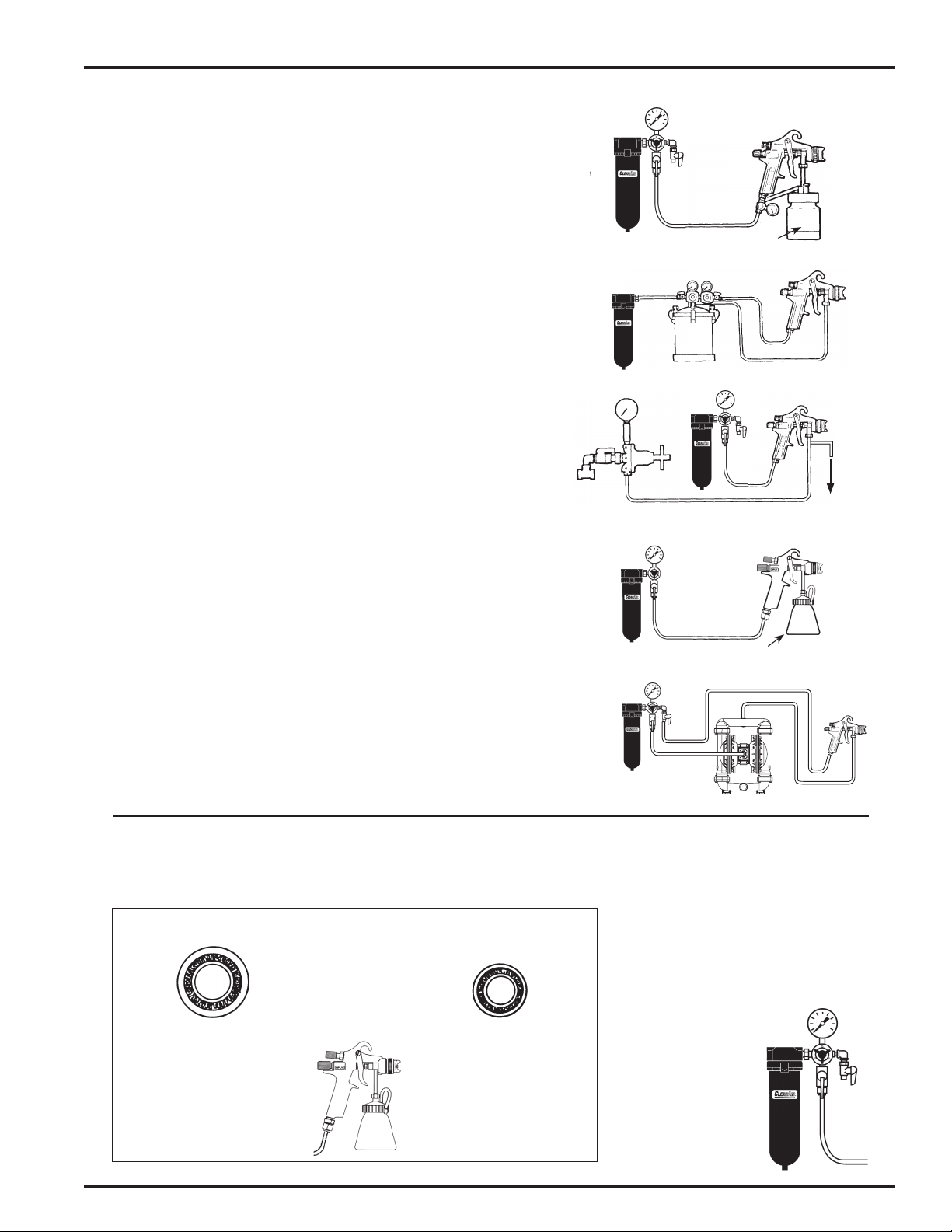
1. Connect the gun to a clean, moisture and oil free air
supply using a conductive hose of at least 5/16 in I.D.
NOTE
Depending on hose length, larger I.D. hose may be required. Install
an air gauge at the gun handle. See page 5 for operating pressures.
Do not use more pressure than is necessary to atomize the material
being applied. Excess pressure will create additional overspray and
reduce transfer efficiency.
NOTE
If quick connect couplings are required, use only high flow quick
connects approved for HVLP use. Other types will not flow
enough air for correct gun operation.
NOTE
If an air adjusting valve is used at the gun inlet, use HAV-501
adjusting valve.
2. SIPHON MODELS ONLY. Purchase cup separately.
Recommended cup: 8 oz. polyethylene cup (81-384). Use
adapter (AD-404) supplied with the cup. Attach the cup
lid assembly to the fluid inlet connector.
3. PRESSURE FEED MODELS. Connect the fluid supply
hose to fluid inlet connector.
OPERATION
SIPHON MODELS
1. Mix coating material to manufacturer’s instructions and
strain material.
2. Fill the cup to no more than 3/4 inch from the top of the
cup. DO NOT OVERFILL.
3. Attach to cup lid.
ALL MODELS
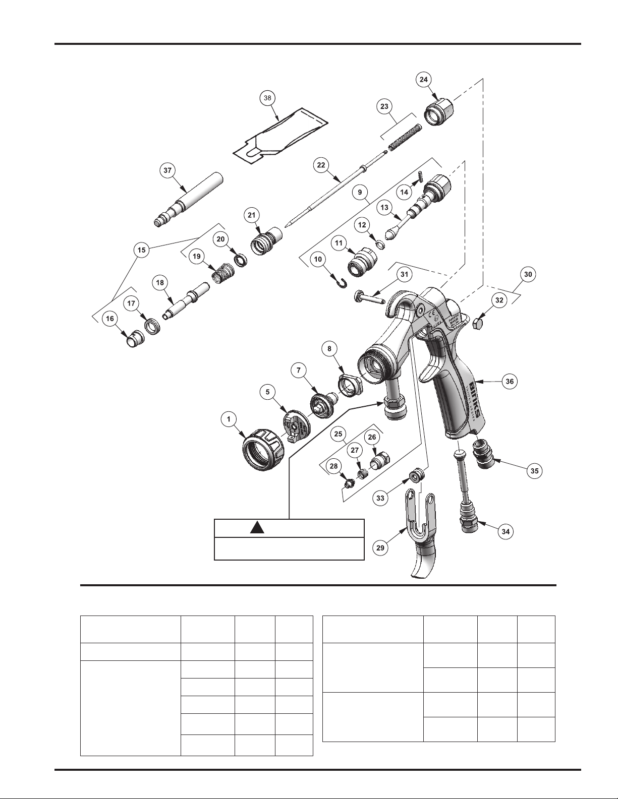
4. Turn fluid adjusting knob (24) clockwise to prevent fluid
needle movement.
5. Turn sideport control (9) counter clockwise to fully open.
6. Adjust inlet air pressure if required.
7. Turn fluid adjusting knob counter clockwise until first
thread shows.
8. Test spray. If the finish is too dry, reduce airflow by
reducing air inlet pressure.
9. If finish is too wet, reduce fluid flow by turning fluid
adjusting knob (24) clockwise. If atomization is too
coarse, increase inlet air pressure. If too fine, reduce inlet
pressure.
10. The pattern size can be reduced by turning sideport
control (9) clockwise.
11. Hold gun perpendicular to surface being sprayed. Arcing
or tilting may result in uneven coating.
12. The recommended spray distance is 8 inches.
13. Spray edges first. Overlap each stroke a minimum of
75%. Move gun at a constant speed.
14. Always turn off air supply and relieve pressure when gun
is not in use.
PREVENTIVE MAINTENANCE
AND CLEANING
To clean air cap and fluid nozzle, brush exterior with a stiff
bristle brush. If necessary to clean cap holes, use a broom
straw or toothpick if possible. If a wire or hard instrument is
used, extreme care must be used to prevent scratching or
burring of the holes which will cause a distorted spray pattern.
To clean fluid passages, remove excess material from gun,
then flush with gun wash solution. Wipe the gun exterior with
a dampened cloth. Never completely immerse in any solvent
or cleaning solutions as this is detrimental to the lubricants
and life of the spray gun.
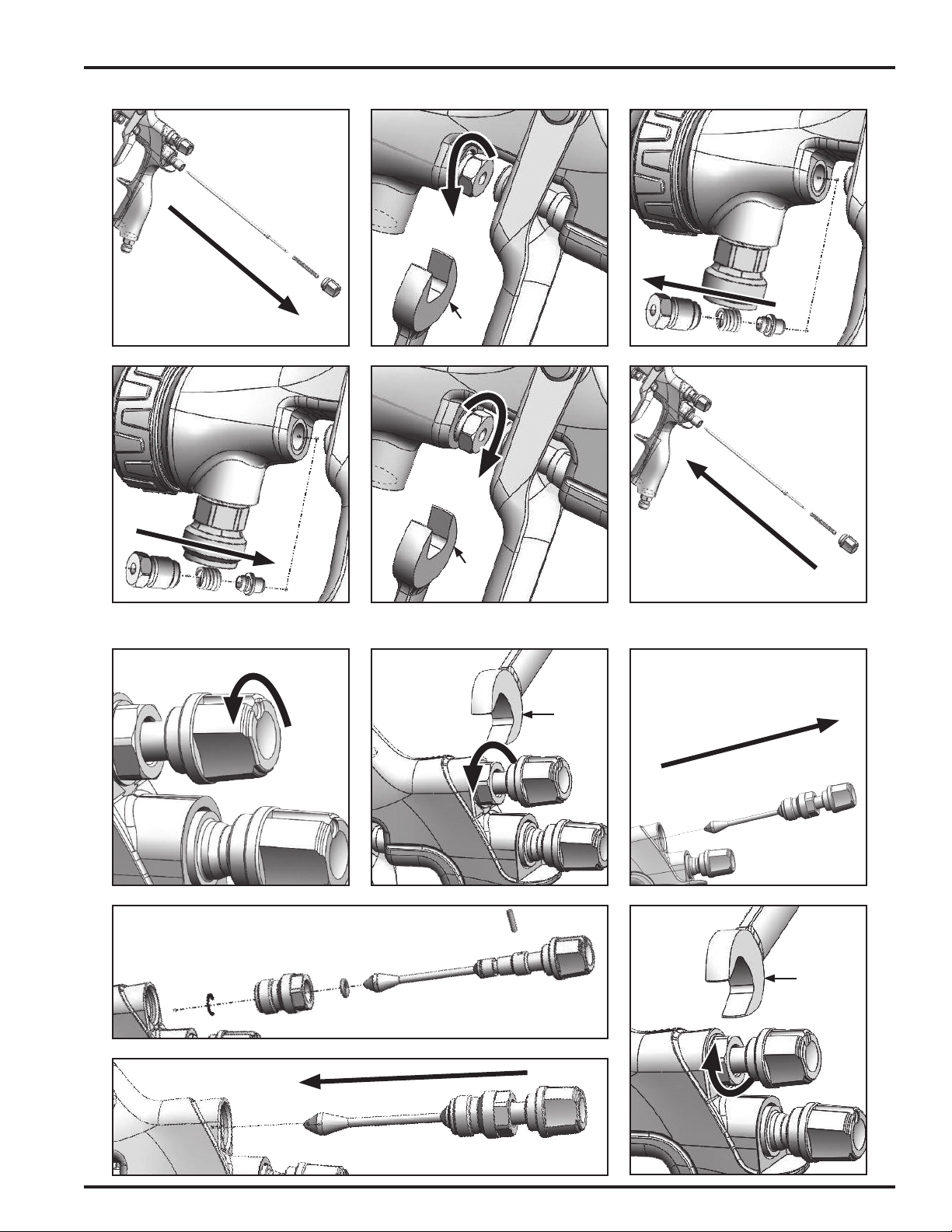
NOTE
When replacing the fluid nozzle (7) or fluid needle (22), replace
both at the same time. Using worn parts can cause fluid leakage.
See page 4. Also, replace the needle packing at this time. Torque
the fluid nozzle to 170–180 inch-lbs. Do not over tighten.
!
CAUTION
To prevent damage to fluid nozzle (7) or fluid needle (22), be sure
to either 1) pull the trigger and hold while tightening or loosening
the fluid nozzle, or 2) remove fluid adjusting knob (24) to relieve
spring pressure against needle collar.
SIPHON CUP. Empty excess material and clean the cup.
Make sure the vent hole in the lid is clear.
NOTE
Before using the spray gun, flush it with solvent to ensure that
the fluid passages are clean.
EN
77-3042-R6 (3/2022)6 / 16www.carlisleft.com

FIG.13
FIG.17
FIG.2
FIG.4
FIG.5
FIG.6
FIG.7
FIG.8
FIG.10
FIG.11
FIG.12
FIG.14
DISASSEMBLY
FIG.3
6mm
FIG.15
6mm
150 – 170 in-lbs
(16.9 – 19.2 Nm)
FIG.9
ASSEMBLY
FIG.16
FIG.1
NEEDLE AND VALVE DISASSEMBLY AND ASSEMBLY
REMOVAL AND INSTALLATION PROCEDURES
EN
77-3042-R6 (3/2022) 7 / 16 www.carlisleft.com

MAINTENANCE – FLUID NOZZLE AND BAFFLE REMOVAL AND INSTALLATION
FIG.1 FIG.2 FIG.3
FIG.4 FIG.5 FIG.6
FIG.7 FIG.8
1/4"
1/4"
170–180 in-lbs.
(19 – 20 Nm)
EN
77-3042-R6 (3/2022)8 / 16www.carlisleft.com

MAINTENANCE – NEEDLE PACKING REMOVAL AND INSTALLATION
MAINTENANCE – SIDEPORT REMOVAL AND INSTALLATION
FIG.1
FIG.2 FIG.3
FIG.4 FIG.5
FIG.1 FIG.2 FIG.3
FIG.4 FIG.6
FIG.5
FIG.6
3/8"
3/8"
14 mm
14 mm
EN
77-3042-R6 (3/2022) 9 / 16 www.carlisleft.com

CONDITION CAUSE CORRECTION
Heavy top or
bottom pattern
Horn holes plugged.
Obstruction on top or bottom of uid tip.
Cap and/or tip seat dirty.
Clean. Ream with non-metallic point.
Clean.
Clean.
Heavy right or left
side pattern
Left or right side horn holes plugged.
Dirt on left or right side of uid tip.
Clean. Ream with non-metallic point.
Clean.
Remedies for the top-heavy, bottom-heavy, right-heavy, and left-heavy patterns:
1. Determine if the obstruction is on the air cap or the uid tip. Do this by making a test
spray pattern. Then, rotate the cap one-half turn and spray another pattern. If the defect
is inverted, obstruction is on the air cap. Clean the air cap as previously instructed.
2. If the defect is not inverted, it is on the uid tip. Check for a ne burr on the edge of the
uid tip. Remove with #600 wet or dry sand paper.
3. Check for dried paint just inside the opening; remove by washing with solvent.
Heavy center pattern
Fluid ow too high for atomization air.
Material ow exceeds air cap's capacity.
Spreader adjustment valve set too low.
Atomizing pressure too low.
Material too thick.
Balance air pressure and uid ow. Increase
spray pattern width with spreader
adjustment valve.
Thin or lower uid ow.
Adjust.
Increase pressure.
Thin to proper consistency.
Split spray pattern
Atomization air pressure too high.
Fluid ow too low.
Spreader adjusting valve set too high.
Reduce at transformer or gun.
Increase uid ow (increases gun handling
speed).
Adjust.
Jerky or uttering spray
*Loose or damaged uid tip/seat.
Material level too low.
Container tipped too far.
Obstruction in uid passage.
Dry or loose uid needle packing nut.
Tighten or replace.
Rell.
Hold more upright.
Backush with solvent.
Lubricate or tighten.
Unable to get round
spray
Spreader adjustment screw not seating
properly.
Air cap retaining ring loose.
Clean or replace.
Tighten.
Will not spray
No air pressure at gun.
Fluid needle adjusting screw not open
enough.
Fluid too heavy for gravity feed.
Check air supply and air lines, blow out gun
air passages.
Open uid needle adjusting screw.
Thin material and/or change to larger tip size.
Paint bubbles in cup
Fluid tip not tight. Tighten tip.
Fluid leaking or
dripping from cup lid
Cup lid loose.
Dirty threads on cup or lid.
Cracked cup or lid.
Tighten lid.
Clean.
Replace cup and lid.
TROUBLESHOOTING
*Most common problem.
EN
77-3042-R6 (3/2022)10 / 16www.carlisleft.com

CONDITION CAUSE CORRECTION
Starved spray pattern
Inadequate material ow.
Low atomization air pressure.
Back uid adjusting screw out to rst thread,
or change to larger tip size.
Increase air pressure and rebalance gun.
Excessive overspray
Too much atomization air pressure.
Gun too far from work surface.
Improper stroking (arcing, gun motion too
fast).
Reduce pressure.
Adjust to proper distance.
Move at moderate pace, parallel to work
surface.
Excessive fog
Too much or too fast-drying thinner.
Too much atomization (air pressure.)
Remix properly.
Reduce air pressure.
Dry spray
Air pressure too high.
Gun tip too far from work surface.
Gun motion too fast.
Gun out of adjustment.
Reduce air pressure.
Adjust to proper distance.
Slow down.
Adjust.
Fluid leaking from
packing nut
Packing nut loose.
Packing worn or dry.
Tighten, do not bind needle.
Replace or lubricate.
Fluid leaking or
dripping from front of
gun
Packing nut too tight.
Dry packing.
Fluid tip or needle worn or damaged.
Foreign matter in tip.
Fluid needle spring broken.
Wrong size needle or tip.
Adjust.
Lubricate.
Replace tip and needle.
Clean.
Replace.
Replace.
Fluid dripping or
leaking from bottom of
cup
Cup loose on gun.
Cup gasket worn or missing below cup.
Cup threads dirty.
Tighten.
Replace cup gasket.
Clean.
Runs and sags
Too much material ow.
Material too thin.
Gun tilted on an angle, or gun motion too
slow.
Adjust gun or reduce uid ow.
Mix properly or apply light coats.
Hold gun at right angle to work and adapt to
proper gun technique.
Thin, sandy coarse nish
drying before it ows
out
Gun too far from surface.
Too much air pressure.
Improper thinner being used.
Check distance. Normally approximately 8".
Reduce air pressure and check spray pattern.
Follow paint manufacturer's mixing
instructions.
Thick, dimpled nish
"orange peel"
Gun too close to surface.
Too much material coarsely atomized.
Air pressure too low.
Improper thinner being used.
Material not properly mixed.
Surface rough, oily, dirty.
Check distance. Normally approximately 8".
Follow paint manufacturer's mixing
instructions.
Increase air pressure or reduce uid ow.
Follow paint manufacturer's mixing
instructions.
Follow paint manufacturer's mixing
instructions.
Properly clean and prepare.
TROUBLESHOOTING
EN
77-3042-R6 (3/2022) 11 / 16 www.carlisleft.com

HAV-500 OR HAV-501
Adjusting Valve
(HAV-501 SHOWN)
HAV-500 does not have
pressure gauge. Use to control
air usage at gun.
6-429 Binks
Gunners
Mate Lube
(Twenty
2 oz. bottles)
Compatible with all
paint materials; con-
tains no silicone or
petroleum distillates to
contaminate paint.SDS
available upon request.
HC-4419 Stem
1/4" NPT(F)
Gun End
HC-4719 Coupler
1/4" NPT(M)
Hose End
NIOSH-Certied, for respiratory protection
in atmospheres not immediately danger-
ous to life.
Medium Large
40-128 40-143
Millennium 3000
Twin Cartridge
Paint Spray Respirator
192212 Professional Spray Gun
Cleaning Kit
Contains six precision tools designed to eectively clean
all DeVilbiss, Binks, Finishline and other brand spray guns.
ACCESSORIES
HAF-507
Whirlwind™
In-Line Air Filter
(sold in multiples of 12)
Removes water, oil, and debris
from the air line.
Quick Connects for
HVLP Guns (Air)
High Flow Type
29-3100-K6 Scrubs®
Hand Cleaner Towels
Scrubs®are a premoistened
handcleaner towelforpainters,
body men and mechanics that
go where you go and no water
is needed.
DPC-69-K1
3/8 NPS Siphon Cup
Adapter Kit
DeKups®Accessories for siphon feed cups
SHELLS LINERS
Optional Siphon Cups
81-384
8 oz. polyethylene cup
Features wide bottom
for stability.
81-540
8 oz. aluminum cup
All metal construction
Star wheel and yoke closure.
AD-404
Adapter
1/4 NPS(m) x 3/8 NPS(f)
HVLP AIR PRESSURES AND FLOWS
GUN INLET PRESSURE
(PSI)
AIR CAP AIR FLOW
(SCFM)
AIR CAP ATOMIZING
PRESSURE (PSI)
5 2.5 2
10 4.0 4
15 5.1 7
21 6.4 10
GUN INLET PRESSURE IS MEASURED AT THE GUN INLET FITTING WITH THE
GUN TRIGGERED.
54-6226 HVLP TEST CAP KIT
EN
77-3042-R6 (3/2022)12 / 16www.carlisleft.com

EN
77-3042-R6 (3/2022) 13 / 16 www.carlisleft.com

EN
77-3042-R6 (3/2022)14 / 16www.carlisleft.com

EN
77-3042-R6 (3/2022) 15 / 16 www.carlisleft.com

EN
77-3042-R6 (3/2022)16 / 16www.carlisleft.com
WARRANTY POLICY
This product is covered by Carlisle Fluid Technologies’ materials and workmanship limited warranty.
The use of any parts or accessories, from a source other than Carlisle Fluid Technologies,
will void all warranties. Failure to reasonably follow any maintenance guidance provided
may invalidate any warranty.
For specic warranty information please contact Carlisle Fluid Technologies.
Carlisle Fluid Technologies is a global leader in innovative nishing technologies.
Carlisle Fluid Technologies reserves the right to modify equipment specications without prior notice.
BGK™, Binks®, DeVilbiss®, Hosco®, MS®, and Ransburg®
are all registered trademarks of Carlisle Fluid Technologies, Inc.
©2022 Carlisle Fluid Technologies, Inc.
All rights reserved.
For technical assistance or to locate an authorized distributor,
contact one of our international sales and customer support locations.
Region Industrial/Automotive Automotive Renishing
Americas Tel: 1-800-992-4657 Tel: 1-800-445-3988
Fax: 1-888-246-5732 Fax: 1-800-445-6643
Europe, Africa,
Middle East, India
Tel: +44 (0)1202 571 111
Fax: +44 (0)1202 573 488
China Tel: +8621-3373 0108
Fax: +8621-3373 0308
Japan Tel: +81 45 785 6421
Fax: +81 45 785 6517
Australia Tel: +61 (0) 2 8525 7555
Fax: +61 (0) 2 8525 7575
For the latest information about our products, visit www.carlisleft.com
16430 North Scottsdale Rd., Suite 450 Scottsdale, AZ 85254 USA
This manual suits for next models
10
Table of contents
Other Carlisle Fluid Technologies Paint Sprayer manuals
Popular Paint Sprayer manuals by other brands

Nordson
Nordson Sure Coat Series Customer product manual

Jacto
Jacto PJB-16 Operator's manual

FAST AG Solutions
FAST AG Solutions Fast Sprayers 9500 Series Operator's manual

turbineaire
turbineaire 1245GT Operator's manual

Graco
Graco EnergyComplete 313221H Instructions - parts

ORTHO
ORTHO Pro Poly Bak-Pak 67184 instructions