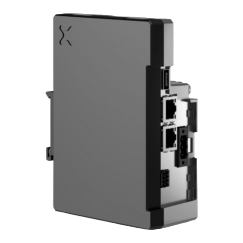
CARLO GAVAZZI SIUTCP2 User manual

SIUTCP2 Installation and operation manual
All the information provided with this document are property of Carlo Gavazzi Controls SpA
1
SIUTCP2 and SIUTCP3
installation and operation manual

SIUTCP2 Installation and operation manual
All the information provided with this document are property of Carlo Gavazzi Controls SpA
2

SIUTCP2 Installation and operation manual
All the information provided with this document are property of Carlo Gavazzi Controls SpA
3
1 Summary
1
SUMMARY ...................................................................................................................................... 3
2
IMPORTANT NOTES......................................................................................................................... 4
2.1
S
YSTEM LAYOUT
...................................................................................................................................... 5
2.2
D
IMENSIONS
........................................................................................................................................... 7
2.3
P
ACKING LIST
.......................................................................................................................................... 8
2.4
S
ERIAL PORTS
’
PIN ASSIGNMENT
................................................................................................................. 8
2.5
LED
I
NDICATORS
..................................................................................................................................... 9
3
ELECTRICAL CONNECTIONS ............................................................................................................ 10
3.1
I
NSTALLATION
P
ROCEDURES
.................................................................................................................... 10
3.2
C
ONNECTING THE
E
THERNET
LAN
ADAPTOR TO A
PC .................................................................................. 10
3.3
C
ONNECTING THE
RS-485
PORTS TO A SERIAL
RS-485
NET ORK
................................................................. 11
4
SIUTCP2/3 CONFIGURATION.......................................................................................................... 12
4.1
C
ONFIGURATION STEPS
........................................................................................................................... 12
4.2
N
ET ORK
S
ETTINGS
.............................................................................................................................. 15
4.3
COM
P
ORT
S
ETTINGS
............................................................................................................................ 16
4.4
D
EFINITION OF A
V
IRTUAL
COM
(O
NLY FOR
SIUTCP2)............................................................................... 20
4.5
O
THER FUNCTIONS OF
S
ERIAL
M
ANAGER
................................................................................................... 24
4.6
O
THER FUNCTIONS OF
D
EVICE
V
IE
.......................................................................................................... 26
5
APPENDIX ..................................................................................................................................... 27
5.1
MODBUS
OVER
S
ERIAL LINE
(RS-485)
GUIDELINES
.................................................................................... 27
5.1.1
Introduction ............................................................................................................................... 27
5.1.2
RS-485 cable............................................................................................................................... 27
5.1.3
RS-485 grounding ...................................................................................................................... 28
5.1.4
RS-485 shielding......................................................................................................................... 28
5.1.5
RS-485 topology......................................................................................................................... 28
5.1.6
RS-485 ter ination.................................................................................................................... 29
5.1.7
RS-485 MODBUS line polarization. ............................................................................................ 29
5.1.8
RS-485 wiring procedure............................................................................................................ 30
5.1.9
RS-485 li its .............................................................................................................................. 30
5.2
LAN
NET ORK GUIDELINES
..................................................................................................................... 31
5.2.1
Cables......................................................................................................................................... 31
5.2.2
Addresses ................................................................................................................................... 31
5.2.3
Ping ............................................................................................................................................ 31

SIUTCP2 Installation and operation manual
All the information provided with this document are property of Carlo Gavazzi Controls SpA
4
2 Important Notes
This document is intended to provide customers with brief descriptions on the product and
to assist customers to get started.
FCC warning
Class A for Ethernet Serial Server (Model SE5001) and for 1-
port Modbus Gateway (Model MB5001C)
This equipment has been tested and found to comply with the limits for a Class A digital device
pursuant to Part 15 of the FCC rules. These limits are designed to provide reasonable protection
against harmful interference when the equipment is operated in a commercial environment. This
equipment generates, uses and radiates radio frequency energy and, if not installed and used in
accordance with the instructions, may cause harmful interference to radio communications.
Operation of this equipment in a residential area is likely to cause harmful interference in which
case the user will be required to correct the interference at his own expenses.
A shielded-type power cord is required in order to meet FCC emission limits and also to prevent
interference to the nearby radio and television reception. It is essential that only the supplied power
cord can be used.
Use only shielded cables to connect other devices to this equipment by RS-232 or RS-485 ports.
Be cautioned that changes or modifications not expressly approved by the party responsible for
compliance could void ones authority to operate the equipment.

SIUTCP2 Installation and operation manual
All the information provided with this document are property of Carlo Gavazzi Controls SpA
5
2.1 System layout
SIUTCP2:

SIUTCP2 Installation and operation manual
All the information provided with this document are property of Carlo Gavazzi Controls SpA
6
SIUTCP3:

SIUTCP2 Installation and operation manual
All the information provided with this document are property of Carlo Gavazzi Controls SpA
7
2.2 Dimensions
SIUTCP2 and SIUTCP3:

SIUTCP2 Installation and operation manual
All the information provided with this document are property of Carlo Gavazzi Controls SpA
8
2.3 Packing list
When receiving the SIUTCP2/ SIUTCP3, check that the following items are included into the
package:
Packing list
Item Notes
SE-5001 (SIUTCP2) converter or
MB5001C (SIUTCP3) converter
Serial cable RS 232 serial communication cable
9-30DC 3-pin terminal block power input
Quick start Installation Guide
CD Serial Manager/DeviceView Software Contains the configuration Utility
Wall Mount kit Kit to be mounted for Wall installations (mounting screws included)
2.4 Serial ports’ pin assignment
The pin assignment of the DB9 male connector on both, SIUTCP2 and SIUTCP3, is shown below:
PIN RS-232 RS-485-2W
1 DCD -
2 RXD -
3 TXD Data+(B)
4 DTR
5 GND GND
6 DSR -
7 RTS Data-(A)-
8 CTS -
9 - -

SIUTCP2 Installation and operation manual
All the information provided with this document are property of Carlo Gavazzi Controls SpA
9
2.5 LED Indicators
LAN LED
Message Description
OFF Ethernet disconnected
Blinking with green Data transmission on Ethernet 100Mbps in progress
Blinking with Orange Data transmission on Ethernet 10Mbps in progress
COM port LED
Message Description
OFF No data transmission on COM Port in progress
Blinking Data transmission on COM Port in progress
RUN port LED
Message Description
Blinking (rate 0,5 s) The firmware is running correctly

SIUTCP2 Installation and operation manual
All the information provided with this document are property of Carlo Gavazzi Controls SpA
10
3 Electrical connections
3.1 Installation Procedures
Connect SIUTCP2/SIUTCP3 to power supply (9-30V AC/DC) using the special universal power
adaptor included in the box with SIUTCP2/SIUTCP3.
3.2 Connecting the Ethernet LAN adaptor to a PC
Connect the SE5001 to the Ethernet network through the Ethernet cable (please, use a standard
straight-through Ethernet cable if the converter is connected to a hub/switch, while a cross-over
Ethernet cable if the converter is connected directly to one’s PC. In this case it is necessary to
make sure the PC to be in the same Ethernet network of the converter;
Ethernet based connection to SIUTCP2
Direct SIUTCP2
/SIUTCP3 to PC connection: use a
RJ45 to RJ45 cross
-over cable
SIUTCP2 PC
SIUTCP2
/SIUTCP3 to PC connection using an Ethernet
Switch: use 2 RJ
45 to RJ45 direct cable
Switch
PC
SIUTCP2

SIUTCP2 Installation and operation manual
All the information provided with this document are property of Carlo Gavazzi Controls SpA
11
IMPORTANT NOTE: the device is provided with a RESET button which restores the system at its
basic factory defaults.
3.3 Connecting the RS-485 ports to a serial RS-485 network
Connect the SE5001 or the MB5001C’s serial port to a serial device;
The connection to a serial RS-485 bus must be done following the relevant best practices. Please,
read the appendix “Modbus over serial line guidelines” at the end of this document.
An RS-485 network installed or operated without following the relevant prescriptions and guidelines
can cause problems to data communication and damages to the connected devices.
IMPORTANT NOTE: Both the converters have been tested ONLY with the 2-WIRES RS-485 and
the RS-232 connection.

SIUTCP2 Installation and operation manual
All the information provided with this document are property of Carlo Gavazzi Controls SpA
12
4 SIUTCP2/3 configuration
4.1 Configuration steps
The default settings present on the converter are equal and shown in the table below:
Default Setting Default User Name & Password
IP: 10.0.50.100 User Name: admin
Gateway: 10.0.50.254 Password. Null (leave it blank)
Subnet: 255.255.0.0
Below you can find the sequence of steps to follow for a complete configuration of the converter.
•Set a new IP address on the converter
It is possible to set a new IP address on the converter by modifying your current PC network
parameters;
The new IP address which is necessary to define on the PC, has to belong to the same octet of the
default IP address set on the converter; the Subnet Mask and Gateway have to be exactly the
same ones defined on the converter.
Please, note that in this case the PC has to be completely disconnected from the Network LAN
You can do it using two different wiring connections:
•by connecting the PC directly to the converter through a cross-over Ethernet cable (for a
easier set-up)
•by connecting both the PC and the converter to a switch/hub using a standard straight-
through Ethernet cable
Once the PC network settings have been changed as described above, you can try to ping
the converter in order to check if the communication between the PC and the converter is
present.
•Install the Serial Manager Software (SIUTCP2) or the DeviceView software (SIUTCP3)
which come with the CD included in the box and run it.
•
IMPORTANT NOTE: The operation and settings of both the software are exactly the same, except
for the settings of the COM Port. Below you will find the ones related to settings of the Network
using the Serial Manager one: Later on, when dealing with the configuration of the COM port, both
of the software will be shown.
If the settings of your PC have been set correctly, the following window will appear:

SIUTCP2 Installation and operation manual
All the information provided with this document are property of Carlo Gavazzi Controls SpA
13
Serial Manager:
DeviceView:
The converter is automatically recognized; if not, please press the first button:
Once the converter has been recognized, please highlighted it and then press the Internet
icon” (alternatively you can launch the browser and digit the IP address of the converter)
The following authentication screen appears:
Please, type in the username and the password and then click on OK. The username is admin and
the password is a blank by default.

SIUTCP2 Installation and operation manual
All the information provided with this document are property of Carlo Gavazzi Controls SpA
14
The following overview page appears:
SIUTCP2:
SIUTCP3:

SIUTCP2 Installation and operation manual
All the information provided with this document are property of Carlo Gavazzi Controls SpA
15
4.2 Network Settings
To be able to enter the Network setup menu, please click on “Networking” option in the left list:
Modify the IP address, the Gateway and the Subnet Mask according to your network settings.
Notice that the Default Gateway and the Subnet Musk have to be exactly the ones defined on your
PC Network settings, while the IP address has to belong to the same octet.
Example:
PC Settings:

SIUTCP2 Installation and operation manual
All the information provided with this document are property of Carlo Gavazzi Controls SpA
16
Converter settings:
Once you set all requested parameters, press the button: “Save configuration”.
If the update is successful, the following screen appears:
4.3 COM Port Settings
SIUTCP2:
Press the COM1 option on the left list:

SIUTCP2 Installation and operation manual
All the information provided with this document are property of Carlo Gavazzi Controls SpA
17
The following window appears. Please, select and set different parameters according to the below
reported indications:
Before leaving the Webpage, press the button “Save”.
1 2
4
3
The default value
is 4660.
Please, set it on
502 as shown
The default value
is 1. Please, set
it on
4
as shown

SIUTCP2 Installation and operation manual
All the information provided with this document are property of Carlo Gavazzi Controls SpA
18
SIUTCP3:
Press the “COM1” option on the left list in order to select the desired serial communication port:
the following windows appears:
Press the button “Save Configuration”.

SIUTCP2 Installation and operation manual
All the information provided with this document are property of Carlo Gavazzi Controls SpA
19
Press the “MODBUS” option on the left list in order to set all parameters related to the chosen
serial communication port:
Before leaving the Webpage, press the button “Save Configuration”.
The default port
value is 4660.
Set it on 502
The default port
value is 1. Set it
on 4

SIUTCP2 Installation and operation manual
All the information provided with this document are property of Carlo Gavazzi Controls SpA
20
4.4 Definition of a Virtual COM (Only for SIUTCP2)
Run Serial Manager and, after having highlighted the interested converter select option “Virtual
COM” from the top menu toolbar:
Choose from the pull down menu: “Configuration show”
The following window appears; the window is split in two different parts:
•the top part: A
•the bottom part: B
This manual suits for next models
3
Table of contents
Other CARLO GAVAZZI Gateway manuals
Popular Gateway manuals by other brands

Samsara
Samsara IG41 install guide

AudioCodes
AudioCodes Mediant 2000 installation guide

Anybus
Anybus AB7702 installation guide

Intel
Intel IoT Gateway Development KitDK200 Series Getting started guide

Industrial Scientific
Industrial Scientific RGX Series product manual

ADTRAN
ADTRAN NetVanta 644 Specifications