X-LED-Power Supply
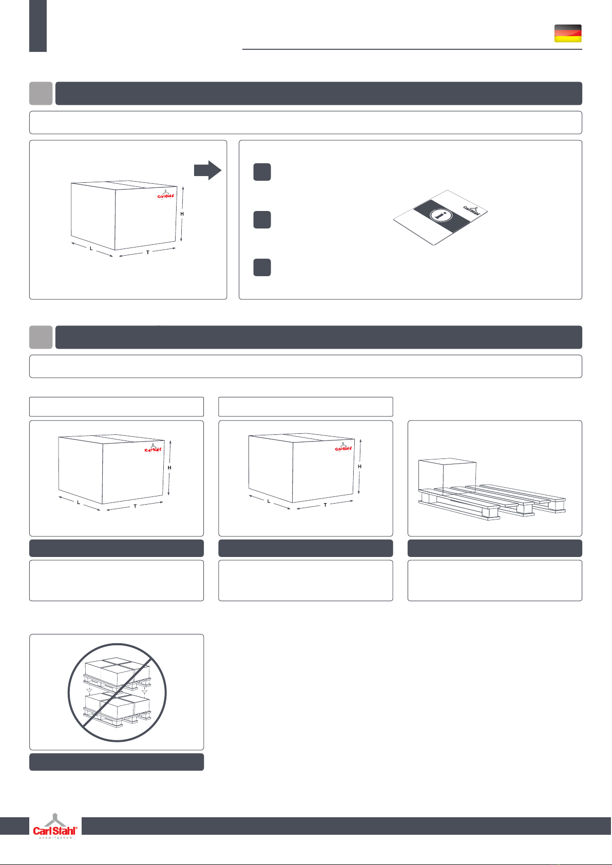
• Besuchen Sie vor der Installation des Produkts bitte
die Produktseite unter um die aktuellenwww.x-led.de
Installationsanweisungen herunterzuladen.
Die Geräte sollten ausschließlich von qualifiziertem Fachpersonal
in Übereinstimmung mit allen geltenden Vorschriften installiert werden.
1 SICHERHEITSHINWEISE
• Beachten Sie immer die technischen Daten auf dem Datenblatt.
• Technische Änderungen vorbehalten.
• Die beigefügte Gebrauchsanleitung ist Voraussetzung
für den ordnungsgemäßen Gebrauch.
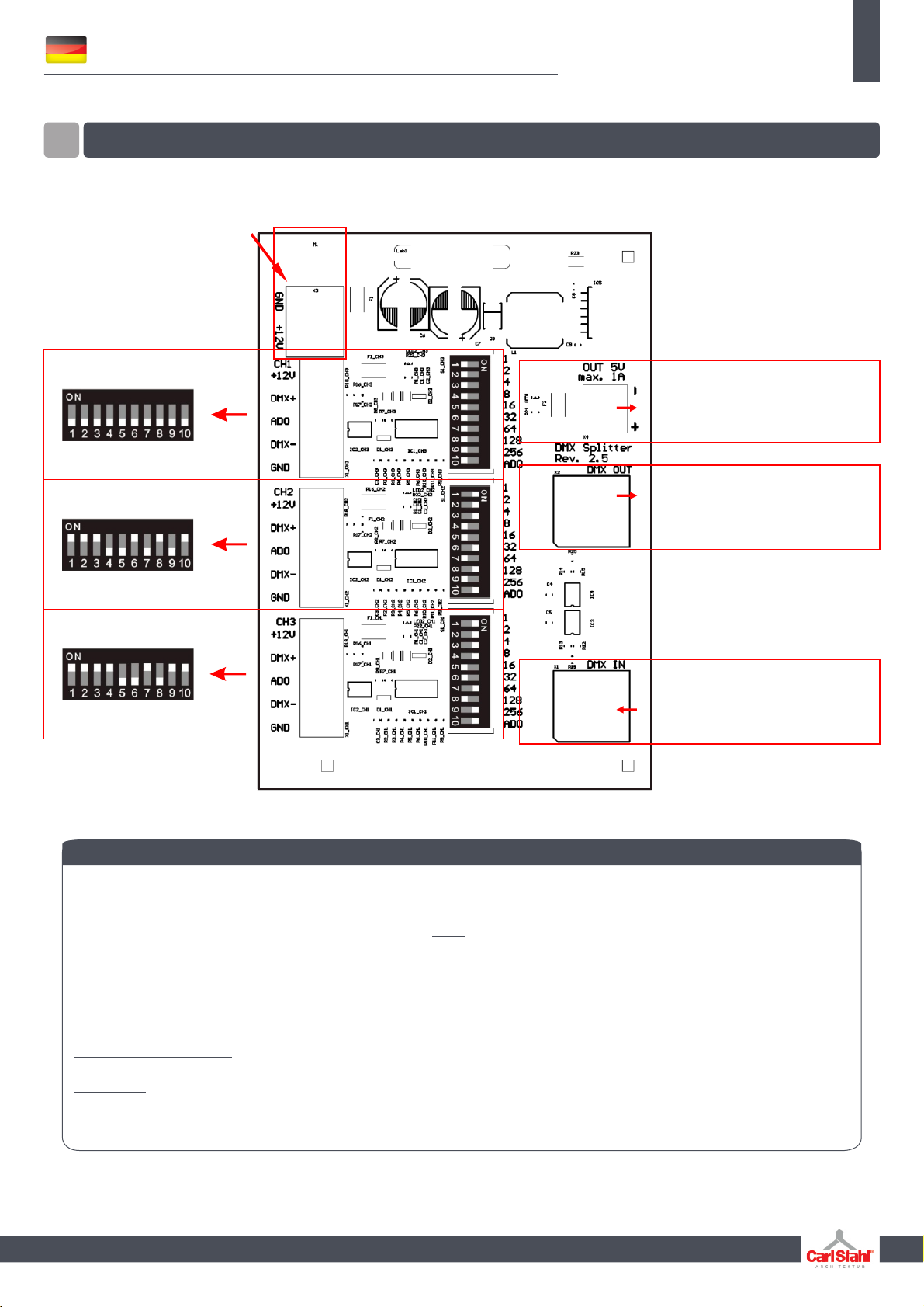
• Die Aderbelegung ist gemäß Schaltschema zu beachten!
• Achtung! Vor Beginn der Arbeiten ist die Netzleitung (230V)
spannungsfrei zu schalten!
• Der Schutz gegen elektrischen Schlag ist beim Einbau
sicherzustellen. Wir empfehlen die bauseitige Absicherung
über einen Fehlerstrom Schutzschalter.
• Beim Einbau ist darauf zu achten dass benachbarte Bauteile
einer Temperatur von 90°C standhalten.
• Elektronische Betriebsgeräte nicht gemeinsam mit induktiven
Lasten (Leuchtstoffl ampen, Entladungslampen, Ventilatoren
usw.) im gleichen Stromkreis betreiben. Beim Schalten in-
duktiver Lasten können Defekte am Betriebsgerät entstehen.
• Wärmedämmung darf nicht auf der Leuchte oder dem Be-
triebsgerät liegen. Beim Einbau ist auf die, in den techni-
schen Daten angegebene, Betriebstemperatur zu achten!
• Vor dem Bohren oder Ausschneiden der Befestigungslöcher
bzw. des Leuchtenausschnittes ist darauf zu achten, das die
eventuell darunter liegenden Netzleitungen nicht beschädigt
werde n .
• Litzendrähte dürfen nicht verlötet werden. Es sind Aderendhülsen
zu ve r w enden.
• Spannungskennzeichnung auf dem Betriebsgerät beachten.
• Ein einwandfreier elektrischer Übergang ist beim Anschließen der
Leuchte an das Betriebsgerät zu gewährleisten.
• Primär- und Sekundärleitungen müssen kreuzungsfrei verlegt
werde n .
• Sekundärleitungen mehrerer Betriebsgeräte dürfen nicht mitein-
ander verbunden werden.
• Das Betriebsgerät darf nur mit angeschlossener Leuchte unter
Spannung gesetzt werden! Wenn die Leuchte unter Spannung
mit dem Netzteil verbunden wird kann die Leuchte beschädigt
werden! (Kein Gewährleistungsfall)
• Jegliche Veränderung ist untersagt. Der Hersteller übernimmt
keine Haftung durch Schäden die durch Veränderung, unsachge-
mäßen Einsatz oder fehlerhafte Montage entstehen.
Gerät vor Nässe schützen.
•
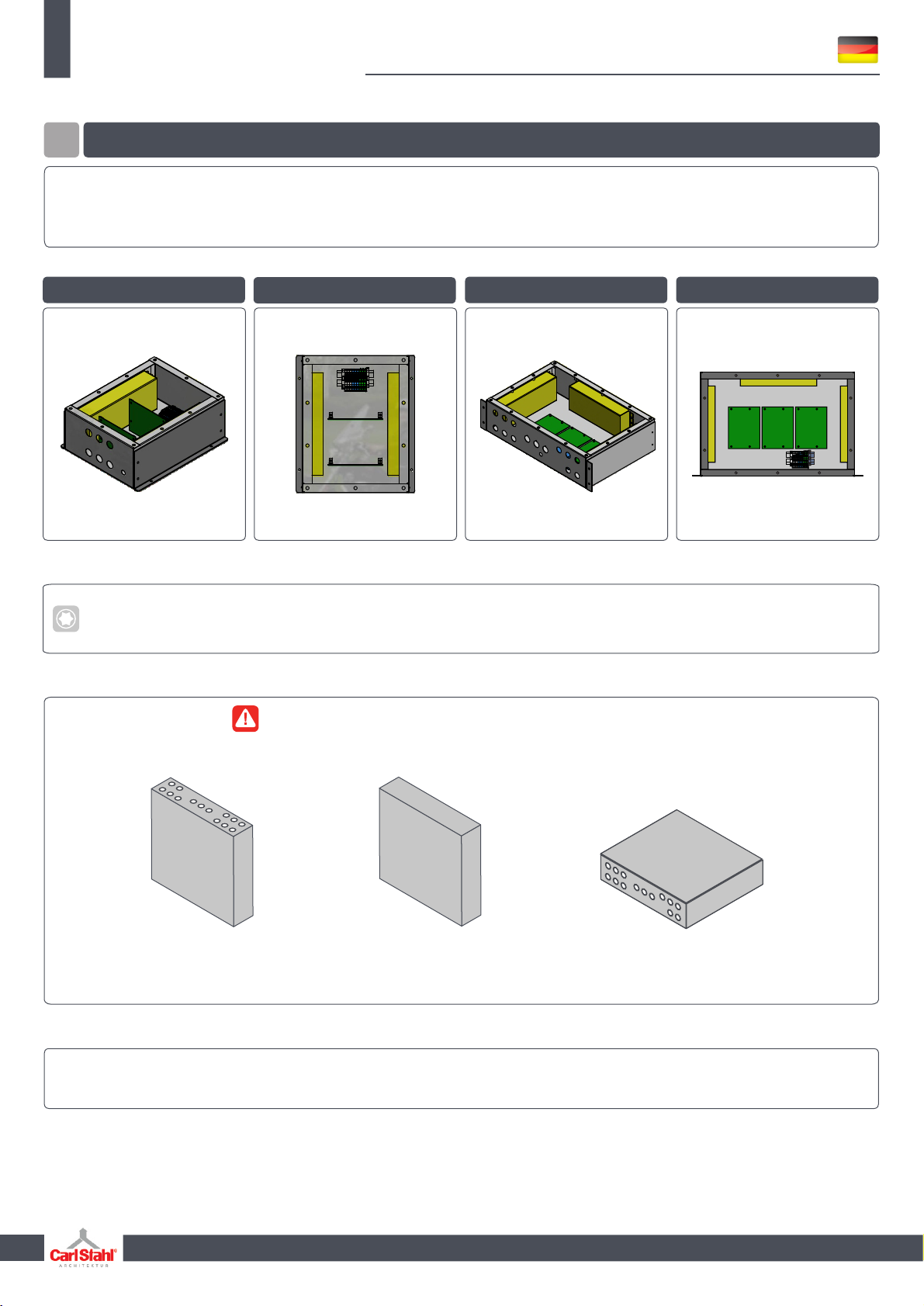
Betriebsgeräte für X-LED-LINE
Das An- und Abklemmen der Leitung darf nur ohne Spannung
•
erfolgen.