(SHEET 1 OF 3)
IS1950A(09/22)
LIANO II WALL SENSOR SOAP DISPENSER
INSTALLATION INSTRUCTIONS
Important Information
Trim kit (2-34) and body kit (1) are supplied separately.
*
Installation
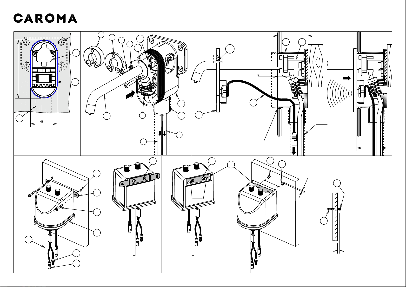
2) Check that the tiling flange on the housing (1a) is flush with the
finished wall/tile face. Fig. 3. Cut if required.
i) Remove protective cover (1c) from mounting body (1b).
ii) Check that the front face of the mounting body(1b) is at least 5mm
from the front of finished wall/tile face. 5mm spacer (4) & 10mm
spacer (3) are provided to bring the outlet forwards if required.
Spacers (3)or (4) can be placed between item (2b) and body (1b),
as shown in Fig. 2.
iii) Insert the soap & air tubes (8) & (9) into the housing (1a) and pass
them through the hole of connection point (1d) as shown in (Fig. 2).
Wire draw/fish tape can be used by carefully tying it to the tubes and
pass through the conduits (not supplied) until the tubes come out
at the open end, Do not pull the soap tubes out forcefully. Place the
mixing valve (7) inside the housing as shown in (Fig. 2 & 3).
iv) Fit the spring washers (6) onto the 3 screws (5).
v) Align the 3 holes on the flange (2b) of outlet (2a) with the holes on
mounting body (1b), insert screw (5) along with washer (6) into the
flange (2b), through the threaded hole in body (1b) then fit the
remaining 2 screws in remaining 2 holes in similar manner, screw
them in and tighten using 3mm allen key.
Roughing kit:
Fit the housing (1a) onto a noggin in the wall and secure using 4
screws (not supplied) through the holes, Fig. 1.
Before tightening, horizontal alignment must be checked by using the
flat face on the top of the housing (1a).
Important:-
1)
*The front face of the mounting plate or noggin must be parallel to the
finished wall/tile face.
To avoid damaging the mounting body(1b) , do not remove the
protective cover(1c) until installing the trim kit.
*
*The rotational alignment of the housing (1a) must be accurate.
Trim kit:
Connection point (1d) is provided for terminating standard 25mm
electrical conduit upto the control unit (12) mounted in front of the wall.
*
vi) Apply a suitable clear sealant to the back edge of the cover plate (10),
leaving an unsealed section at the bottom for drainage. Insert black
sensor cable (11) from the cover plate (10) into housing(1a) and pass
it through the hole of connection point (1d) as shown in (Fig. 3).
Continue feeding the cable through the conduits(not supplied) until the
black cable end comes out the open end in front of the wall. Pass the
hole in the cover plate (10) along with seal (10a) over the outlet as shown
in (Fig.3), slide it back, position the cover plate by keeping the sides
vertical and press firmly to ensure proper seal.
Note: Wire draw/ fish tape can be used by carefully tying it to the cable
end and pass through the conduits(not supplied) until the cable comes
out at the open end in front of the wall.
Determine a suitable location for installation of control unit(12) near the
in-wall conduit exit point before proceeding with control unit mounting.
Important: Do not pull the sensor cables forcefully, as it can damage
the sensor cables or sensor connection.
The soap tube (8), air tube (9) and sensor cable item (14) in the
trim kit are 1.5m long.
*
Both water based & non-water based soap solutions can be used.
Soap solution viscosity should be within 100 to 2500 cps.
For high viscosity soap solutions the foam level knob (33) must be
set to minimum at '-' no air to enable smooth dispensing.
For water based solutions, the foam level knob (33) must be turned
anti-clockwise towards '+' max. air. (See Fig. 10)
*
*Soap control unit must be primed before first use and after every
refill. Follow priming instructions, as shown in Fig.10.
The soap control unit (12) is mains powered only. Separate battery
box (20) is supplied which can be used as a battery backup.
*
The allowable in-wall range from finished wall/tile face to the
noggin is 50 - 60mm, Fig. 3.
The wall/tile cut-out must be 44 x 94mm to ensure enough
sealing surface for cover plate (10), Fig. 1.
*
*
4b) Soap control unit installation (Removable):
6) Battery box installation :
For installation into solid walls; (brick, concrete etc.)
i) Drill two 6mm holes, 40mm deep and 22mm apart vertically
as shown in Fig. 8.
ii) Insert small end of wall plugs (29) into drilled holes and tap until
flush with wall/tile face.
iii) Align the slots on bracket (30) with the holes on the wall, pass the
screws (31) through the slots and insert into the wall plugs (29).
Then tighten the screws DO NOT OVERTIGHTEN.
iv) Slide the battery box (20) onto shoulder of bracket (30).
For installation into timber stud or MDF boards:
i) Drill two holes at 22mm apart vertically to suit the self tapping
screws supplied as shown in Fig. 8.
ii)Align the slots on bracket (30) with the holes on the wall, pass the
screws (31) through the slots and insert into the timber stud.
Then tighten the screws (31). DO NOT OVERTIGHTEN.
iii)Slide the battery box (20) onto the shoulders of bracket (30).
Plug the power supply (21) into the mains and turn it ON.
Determine a suitable location for installation of battery box (20) near the
soap control unit before proceeding with battery box mounting.
iv) Fit the screws (25) and tighten, DO NOT OVERTIGHTEN.
For installation into solid walls; (brick, concrete etc.)
i) Drill two 6mm holes, 52mm apart and 40mm deep horizontally
as shown in Fig. 6.
ii)Insert small end of wall plugs (22) into drilled holes and tap until flush
with wall/tile face.
iii)Insert screws (24) into wall plugs, screw them until the head is 6mm
away from wall/tile face as shown in Fig. 6.
iv)Mount the control unit (12) onto the screws (24).
For installation into timber stud or MDF boards:
i) Drill two holes at 52mm apart horizontally to suit the self tapping
screws supplied as shown in Fig. 6.
ii)Insert screws (24) into the holes and screw them until the head is 6mm
away from wall/tile face as shown in Fig. 6.
iii)Mount the control unit (12) onto the screws (24).
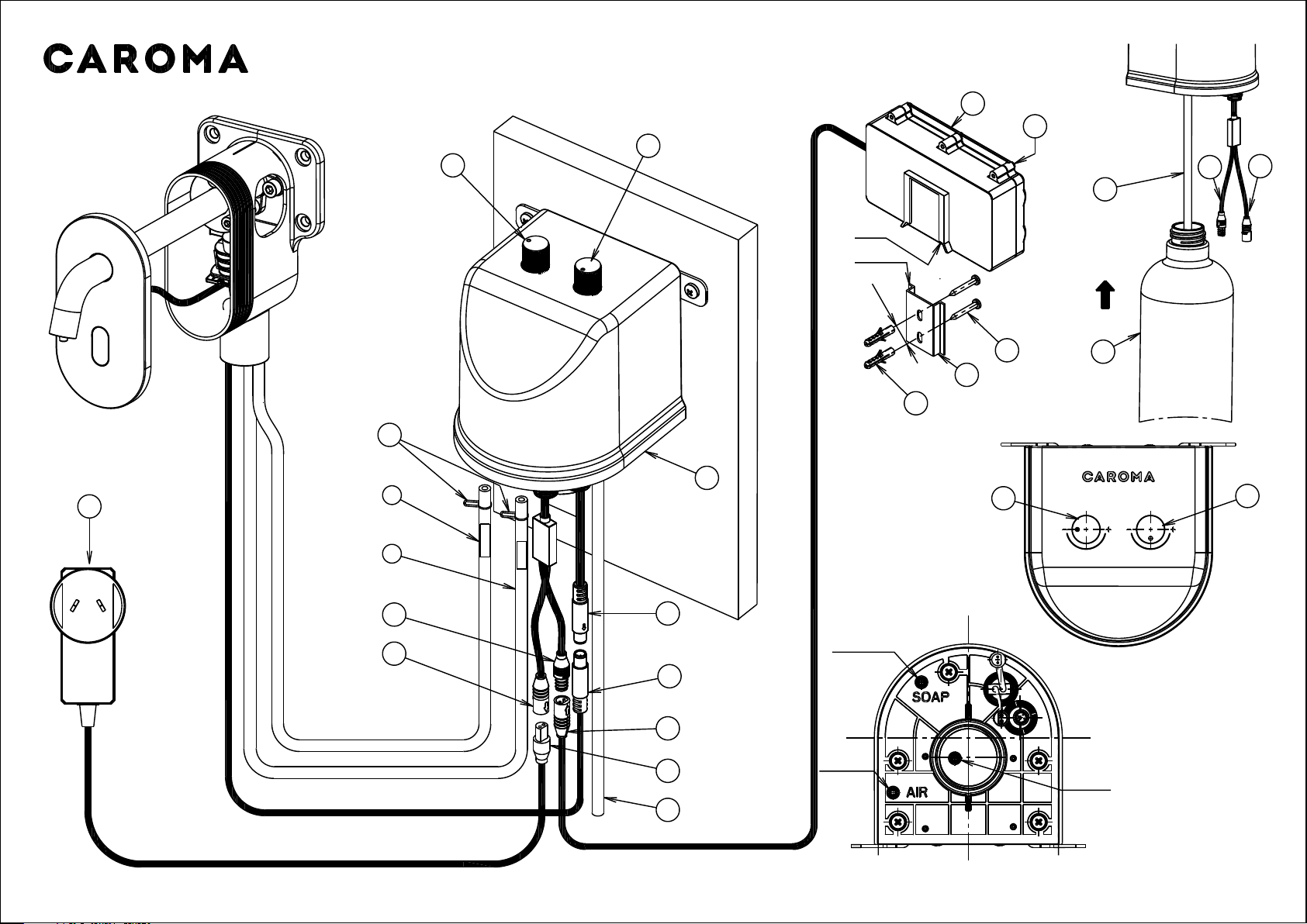
5) Soap Bottle Installation (See Fig. 9)
Pass the soap bottle (27) over the tube (28) coming out of the soap
control unit (12), screw the bottle under the unit and tighten.
Optional removable bracket (supplied) allows the control unit to be lifted
off quickly for easy access to pump functions and bottle re-fill.
i) Remove the screws (25) using a phillips head screw driver.
ii) Remove the wider fixing plate (23) and put it aside.
iii)Take the narrower fixing plate (26) out of the bag, fit it at the back of
the control unit (12) by aligning the holes on the fixing plate (26) with
the holes at the back of the control unit(12). The cut-outs on the plate
should be towards the bottom, as shown in Fig.6.
3) Connections :
a) Soap tube and air tube connections, (Fig. 7 & Fig. 11):
Identify the embossings "SOAP" & "AIR under the soap unit (12).
Press clip (13), slide the clip down the tube labelled "SOAP". Fit
soap tube (8) onto the boss next to embossing "SOAP" Slide the clip
up over the tube (8) and ensure clip (13) is fitted onto groove of the
boss to prevent soap tube from being removed. In the same way,
fit air tube labelled as "AIR" (9) onto the boss next to embossing "AIR".
b) Sensor cable connection, (Fig.7):
By aligning the profile of connectors (14) & (15), connect the sensor
cable (14) from cover plate (10) to the end of sensor cable (15) of
soap control unit as shown in Fig. 7.
c) Power cable connection:
While aligning the 'D' profile of male and female connectors
Connect male connector of power cable (16) to female connector (17)
of soap control unit (12) as shown in Fig. 7. Connect male
connector (18) to female connector (19) of battery box (20).
Ensure all cable connectors are pushed in fully.
4a) Soap Control unit installation (Fixed Mounting):
For installation into solid walls; (brick, concrete etc.)
i) Drill two 6mm holes, 40mm deep and 104mm apart horizontally as
shown in Fig. 4.
ii)Insert small end of wall plugs (22) into drilled holes and tap until flush
with wall/tile face.
iii)Align the slots on fixing plate (23) with the holes on the wall, pass the
screws (24) through the slots and insert into the wall plugs (22). Then
tighten the screws. DO NOT OVERTIGHTEN.
For installation into timber stud/MDF boards:
i) Drill two holes at 104mm apart horizontally to suit the self tapping
screws supplied as shown in Fig. 4.
ii)Align the slots on fixing plate (23) with the holes on the wall, pass the
screws (24) through the slots and insert into the wall plugs (22). Then
tighten the screws. DO NOT OVERTIGHTEN.
Insert/replace 4 x 1.5V 'D' batteries following the "-" & "+" markings.
2)
1) Remove screws (32) using a phillips head screw driver then
put the screws aside, remove the cover of battery box.
7) Adding/Replacing batteries (See Fig. 8)
3)
Fit the cover back on ensuring the seal is in place and compressed.
4)
The flat head screwdriver can be used in the battery box to prise the
cover open.