Lily Corporation CD65 Operation manual

CD65 Certified
Operation and Service Manual
Lily Corporation
240 South Broadway
Aurora, Illinois 60505 - 4205
United States of America
Phone: (01) 630 - 892 - 0860
Fax: (01) 630 - 892 - 5623
Email: [email protected]
Web Site: www.lilycorp.com
© 2000 Lily Corporation
Product Warranty and Disclaimer.................... .2
Safety Precautions.................................................2
THE RESIN SUPPLY
The Options.......................................................3
The Connections ...................................................3
THE AIR SUPPLY
Connections & Requirements ............................4
OPERATION
To Begin With........................................................5
Dispensing..............................................................5
Shot sizing ..............................................................6
Remote Trigger Assembly ..................................7
Shut Down ..............................................................8
Clean-up .................................................................8
Ratio Assurance Check .................................... 10
Changing Ratio ....................................................11
THE SYSTEM, AND HOW IT WORKS
The Fluid Circuit ................................................ 12
Coco Valve Module ........................................... 13
The Fill Sensors ................................................. 13
The Pneumatic Control Circuit....................... 13
SERVICE
Lubrication .......................................................... 14
Coco Module ...................................................... 14
Metering Cylinders ........................................... 18
Trouble Shooting ................................................ 20
APPENDIX - ASSEMBLY IDENTIFICATION
Serial Number

CD65ServiceManual: Ver.1.2,Page 2
EXPRESS WARRANTY AND DISCLAIMER OF IMPLIED WARRANTIES
LilyCorporation unconditionallyguaranteesits products tobefree of defectsinmaterial or
workmanshipandfurtherwarrantsthat,foraperiodofthreemonthsfrom dateof factoryshipment, its
productwillmeettheperformancecriteriastated inLily Corporation’spublications.
Thereare no other warranties,expressedor implied, including those ofmerchantabilityand fitness for
particular purposes.
LilyCorporationcautions the usersof its productsthat epoxies mustbemetered atthecorrect ratio andthoroughly
mixedtoachievetheirformulatedstrength. Theuserisfurthercautionedthatthoroughmixingwithinastaticmixing
devicecanonlyoccurwithuniformflowofthetwocomponents.
Transmissionofthecomponentsthroughseparatehosestoaremotemixermay result in unevenflowofthe
componentsduetoswellingandcontractingofthehoses,ordifferentcompressibilityofthematerialcomponents
duetoair content orchemistry.
WARNING AND SAFETY PRECAUTIONS
TheCD65can developfluid pressures inexcess of 2,000pounds per-square-inch (psi).Everyone within25 feet
shouldweareye protectionwhenthe systemisenergized. Mechanical membersareactuated underforcesof upto
500psi.Maiminginjuriescan be incurred. Donotenergizethe system unlessallscreensare in place,andfingers,
tools,and other objectsare outsideof the frameof themachine.
Becomethoroughlyacquaintedwithfirst-aidproceduresrecommendedbyyourresinsupplier in the event resinenters
one’s eyes. Ifsolventsare to beusedfor cleaning, personnelshouldbecome thoroughlyacquaintedwiththeir charac-
teristics. Mostsolventsarehazardous under all circumstancesandextremely dangerous in non-ventilatedareas,orat
elevatedtemperatures.
Athorough understanding ofthe OperatorsManual iscrucial to thesafe operationof theCD65. Do not attemptto
operatethissystemuntilthoroughlyfamiliarwithitscontents. Phone LilyCorporationifclarificationsareneeded.
and finally:
Promptly – andthoroughly – inspectyour shipment fordamageand completeness. If anyitemsare missingor
damaged,immediatelynotifyLilyCorporation. Claimsformissingor damaged itemsmustbetimelyandspecific.

CD65ServiceManual: Ver.1.2,Page 3
Bothresincomponents mustbe delivered tothe CD125
underpressure. Pumpssuch as thatillustrated
fortheA component totheleft are usuallyused
forthispurpose. However,ifthematerial
volumeisrelativelylow,andtheresinisthin,a
pressurevesselsuch as thatshown with theB
componentmaybe adequate.
Anypumpable to pressurizematerialto 500psi
isusuallysuitable. However,stickymaterials
requirehigherpressures. Consultwith Lilyifin
doubt. Asa distributor for the AroProducts
DivisionofIngersollRand,LilyCorporation
offerspumpsandaccessoriesforvirtuallyevery
application.
The Options
Therearefour1/2” JIC fittingsbelowthecontrol panel. The lowerfittingsare
theinlet ports, and the upper, the outlet ports. The base resin ports areon the
left(facingthemachine) and thecatalystonthe right. They arealsomarked A
(Base)and B (Catalyst).
Usea 7/8”wrench to remove the capsand connect the hoses. Some fluid
maydripfromthefittings. Itis a harmless materialusedtotesttheequipment
followingmanufacture,anddoes not needtobe purged fromthesystem before
dispensing.Stowthecapsonthemagneticflangeof the channel.
Leavetheinletfluidfittingsconnected. Theirdisconnectionandre-connection
riskscostlymis-connection.
TheCD65fluid valvesare rated at3,500 psi. Incoming fluidpressure must notexceed this,and should notapproach it
unlessabsoloutlynecessary. The material flow canusuallybeincreasedbyheatingthematerialasmost products thin
dramaticallywithevenminortemperature increases.
.....whenusing the LilyTH30 Hopper Assembly.Mountthepumps by carefully screwing them intothepipe
elbows. Applya teflontape orother lubricant. Do not force the fit! Takecare when starting the threads to avoid
crossthreading.
Thefluidoutletfitting is the lowerofthe two ports onthepump. Theair inlet isfittedwitha pressure gaugeandregula-
tor. Only dry, filtered airshould be usedfor the bestperformanceand life. Seethepump manual forlubrication of the
pumprodsealsbeforeenergizing.
Addmaterial tothe hopperslowly atfirst to check for leakage at the fittings. It is goodpractice tokeep thehoppers
nearlyfilledasitreducestheliklihoodofrunningoutofmaterial,andmakesthepumpmoreefficient. Whenadding
materialinitally,openthedrainvalveinthepipeelbowtoventairwithinthefitting. Leaveitopenuntilmaterialappears.
Thencloseit.
THE RESIN SUPPLY
The Connections

CD65ServiceManual: Ver.1.2,Page 4
Requirements and Connections
Theairfittingsare the ‘press-
to-connect’variety. The
connectionismadebyfirmly
insertingthenylontubingend
intothefitting. Thetubingis
releasedbypullingthefitting
collarfirmlybackagainstthe
fittingbody,whilepullingthe
tubefromthefitting.
Thevolumetricdeliveryrateofthedispenseris determined by theairpressure. Aninadequateairsupplywillresult in
sluggishorsporadicdeliveryof material. A75cfmcompressor is recommendedforthecombined operation ofthe
dispenserandthesupply pumps.
Theairsupplymustbe clean and dry.Acoalescingfilter is fixed tothedispenser,butit will notcleanupcontaminated
air. Itsfunction is to removelubricantsandadditiveslikelytodamagetheseals.Inspect all filters frequently,and
replacethemwhendirty.
Donotallow theair compressor tooverheat! Carbon deposits dueto overheatedcompressor oils willinterfere with
thefunctionofthecontrolvalves.
Donotallowanyadditivesto enter theairsupply. Althoughmanyadditives are beneficialtoair tools,mostwill
damagethe sealsin theCD65 controlcircuit. Never allow products such as WD-40 to enter theair supply. The
periodiclubricationofthepneumatic components isdicussedonpage14.
Alwaysblow out airhoses before connectingto thesupply pumps orthe dispenser. Filters andseperators cannot
managethelargevolumesofmoisturethatmay accumulateinairhosesovernight.
Anairharnessincludesthe connection to thedispenseraswell as the gauges,regulators,fittings,and filter for the
supplypumps. Thepressure setting atthe supply pumpsshould be adequateto meetthe demands ofthe application,
butnohigher. Excessivepressuresresultin unnecessary stress oncomponentsthroughoutthesystem.
The Connections

CD65ServiceManual: Ver.1.2,Page 5
•Purgetheair supply hoseofwater orothercontaminants.
•Cabinetswitchoff.
•Energizethetransferpumps.
•Connectthehoses, manifold,ormixer atthematerial outlet fittings. Closetheoutletvalve.
•Reducethedispenserairpressure to zerobyturningtheregulator counter clockwiseuntilits
springisrelaxed.
•Cabinetscreensin place.
•Eye-washat hand,and goggles on those nearby. Wear otherprotective gear as recom-
mendedbytheresinsupplier.
•Ifdispensinginto a singlelineor a permanantmixer, takestepsI andIIunder Clean-upon
Page8 beforeproceeding.
Connecttheair supply,andswitch thedispenser on. Increase theair pressure atthe dispenserregulatoruntil thereis an
audiblemechanicalshifting. This indicatesthesystemhasbegan to cycle. Slowlyincreasethepressureatthe cabinet
regulatortothemaximumwhilewatchingfor fluidorairleaks.Thispracticewillidentifyanydamagedtubing,seals,or
fittingsbeforethesystemismovedonsite.
Followingthe high pressurecheck, reduce thepressure tothat selected forthe applicationat hand. The dispense
pressuremaybealtered at anytimeby adjusting theregulator. Once thesettinghasbeen selected, theunitwill continue
todispenseatthat pressure untilthesettingis changed.
Note: The dispenser pressure gauge will only
register a reading during a dispense cycle. This is
because it is reading the pressure to the main air
cylinder on its dispense stroke. It is not that of the
resin.
Theresinpressurewillbemuchhigherthanthemain
cylinderpressure.The chart totheright liststheap-
proximaterelationshipbetweentheregulatedcylinder
pressureand the resinpressure at variousratios. This
dataisusuallynotimportantunlessdispensinginto
confinedareas such as cracks.
Dispensing
To Begin With
OPERATION
air regulator
Ratio Factor Cylinder Air Resin
Pressure Pressure
1:1 4.9 100 psi 490 psi
2:1 6.6 660
3:1 7.4 740
4:1 7.9 790
5:1 8.1 810
8:1 9.2 920

CD65ServiceManual: Ver.1.2,Page 6
OPERATION
Shot Sizing
TheCD65dispenserisequippedwith Shot Sizing. This featureallowstheselection
of exact dosages to be repeated.
Theshotdosage issetusing the frictionknob located nextto the sightgauge. To
adjustthe setting, loosenthe nut andslide thevalve up ordown. Move thevalve up
inthe slot to reduce the shot size, and down to increase thedosage. Oncethe
propervolumeisachieved,tightenthenut.
Warning: Whenusingshotsizing,itisadvisabletopositionthemachinehori-
zontal. Ifthedispenseroperatesverticallywiththeshotsizing engaged, any airthat
entersthematerialmay become entrappedandaccumulatebeneath
thematerialpiston. Thisconditioncan cause seriousratioerror,
dependinguponthevolumeofair entrapped.
trappedair
expelledair
Whentheunitishorizontal,anyairthatentersthe metering chamber is promptlyexpelledbeforeitcanaccumulateto
adverselyaffectratio..
Ifit is notfeasible tooperate the dispenser horizontal onits back, stepsmust be takento avoidentrapping airbeneath
thematerialpiston,orallowingittoaccumulate.
Aircaneasilybeentrappedwithinathickmaterialifitisnothandled carefully when transferring it fromoneonecon-
tainertoanother. Toavoid entrapping air, smoothly pourthematerial into thehopperor other container fromwhich it
isto be pumped. Do not dump it as a large mass lest air becomes entrapped in the crevices and pockets of the mate-
rialalreadyinthecontainer.
Ifthematerialistobepumped from its originalcontainer,move the pump tothenextcontainerbeforethematerial level
allowsthepumptocyclewithoutsufficientproductatitsinlet. Ifthishappens,thematerialcavitates,allowing air to
enterthepump.
Purgethesytemperiodically,and immediately ifthereisreason to believeairenteredthe supply pump. Topurgethe
system, movetheshotsizing setting tothebottom of itsslotand dispense atleasttwo full cycles. Carefullyobservethe
colorof the material dispensed duringthis process. Itmay needto be discarded due to poor proportioningif airwas
present. Thisprocedurewill purgethemeteringchambers of anyair. Dothis everyhour or soeven when entrapped
airis not suspected.

CD65ServiceManual: Ver.1.2,Page 7
OPERATION
Remote Trigger Assembly
TheRemoteTrigger Assembly (RTA)controlsthematerialflowfromthedispenseoutlet. Itisusedwith a TSO (Twin
ShutOff)orSSO(SingleShutOff)ControlValve. Anumbilicalcordshuttlesthe control
signalsbetweenthecontrolvalveand the dispenser.
Aligntheumbilicalplug
withitssocketby
matchingtheholeon
theumbilicalwiththe
holeinthe socket.
Tobegindispensing,pressthe
leftbutton. Materialwillflow
untilthedispenserfinishesits
dispensestrokeunlessthe
rightbutton is pressed to abort
theshot.
Therearetwotypes of shut-offvalvestoservedifferentapplications. TheTwin
ShutOffvalve(TSO)controlstheflowofcomponents dispensed through twin
hoses.Thecomponentsarenotjoineduntilwithinaninexpensivestatic mixer.
TheSingleShutOff(SSO) dispenses joinedcomponentsfromasingle hose.
SSOdispensingrequires the useofa Gusto purgetankfor cleaning.
Use and care
TheTSOand SSO valvesretainthe dispensepressurewithin the hosesduring
refillcyclesand after thedispenseris switched offaswell. For safedisconnec-
tion ofthe hoses forcleaning, theymust first be depressurized. To doso,
reducethedispensepressure to zero byturningthe regulator knob counter-clockwiseuntilthespring is relaxed.Then
pressthe startbutton onthe trigger assembly. Thevalves canbe actuatedback
andforthduringcleaningbyalternatingbetween the stopandstartbuttons.
Clean-upconsistsoftheremoval and discardingofthedisposable mixer and
insertinggreaseat the zerkfittings. Onesqueeze of thegreasegun into therear
fittingsissufficient, whiletheforwardfittingsshouldbefilleduntilgreaseflowsfrom
thenozzle.
Itiswiseto grease thethreadsof the mixermountingnozzle each daybefore
installinganewnozzle. Thegreaseassureseasyremoval of the nutbecauseit
preventsepoxyfrombonding to thethreads.
Toconnect the umbilical,remove the caplocatedon the
frontof themachine. Take care not to lose the o ring
sealsbeneath thecap.

CD65ServiceManual: Ver.1.2,Page 8
Clean-up
The GustoPurge tank (Page#32) is usedto cleanhoses, mixers, hosemanifolds, valves,and other components
exposedto catalyzed resin. Complete steps 1 and 2 below tocharge theGusto Purgetank beforestarting injection.
Itisa precaution thatallows clean-up inthe event theairsupply islostdue to compressorfailure. Withthe Gusto
Purgetank fully chargedwithair,there is sufficientenergywithin the tank tocleanupthemajorcomponents.
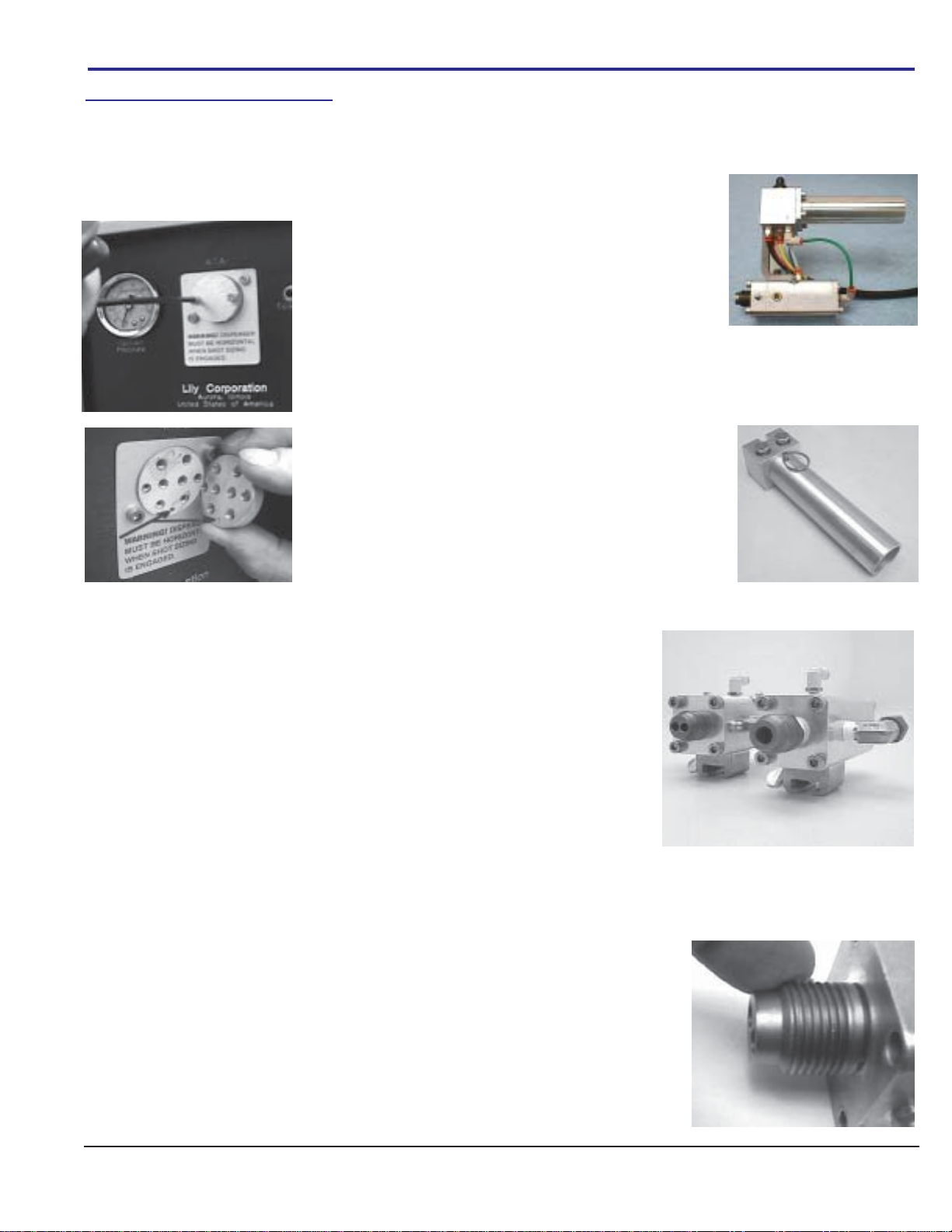
1. Vent the tank by rotating theselector valveso thatit pointsaway fromthe adapterblock,
andtowardsthe bronzefilter. Removethe lid andpour about one-halfgallon of Acetoneor
MethylEthylKetone (MEK) solventinto the tank. Donot use petroleumbasedsolvents
suchastoluol,xylol,mineralspiritsor naptha, as theywilldestroythelidseal. Donot fill the
tank,asthiswillreducethevolumeofair available for anemergencyclean-up.
2. Replacethe lidand secure it with itsbale. Rotate theselector valve 90 degrees sothat it
isclosed to theinlet and outlet. Connectthe airsupply and pressurizethe tankat the maxi-
mumpressureavailable. Setthe tank asideuntiltimeto clean up.
Mostepoxyresinscanbeleftwithinasystemindefinitely. How-
ever,there isa very important step to be takenat shut-downif (a),
alowviscosityresinis being used, and(b), amixerormanifoldis
fixeddirectlytothe outletfittingsofthe Cocomodule. Theproce-
dureiscalled“burping”.
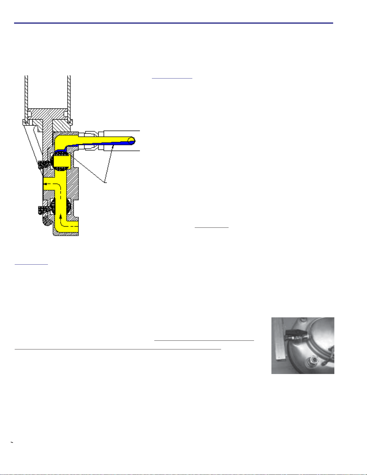
Burpingisnecessary because thebase and catalystcomponentsof
mostthinresinshaveamuchdifferentspecificgravity. Likevinegar
andoilin saladdressing, one isheavierthanthe other,andquickly
sinksto the bottom: the base component tends to sink beneath the
catalyst.Whenthecomponentshovertogetherwithinamixer or
manifoldfixedtotheoutletvalves,itispossiblewithina very few
minutesforthe base topond out beneaththecatalyst, entering the
catalystoutletvalvewithcostlyresultsasithardensovernight.
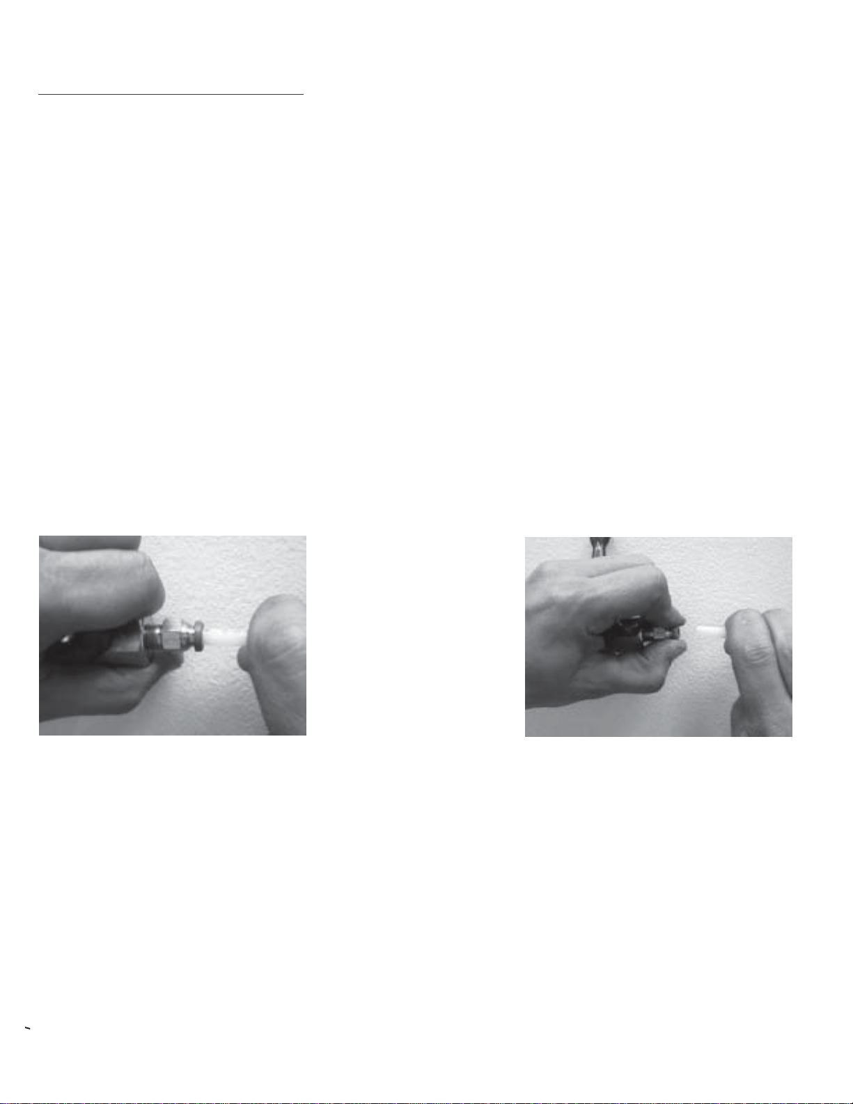
Toburp the unit,simplydispenseafew ounces ofmaterialintoa
wastecontainerimmediatelyafterremovingthemixerormanifold.
Thiswillflushanybaseresinwhichmayhaveenteredthe catalyst
fittingorvalve.
Heavier base
resin ponded
into catalyst
valvefrommixer
Shut Down
OPERATION cont.
Becausetheresincomponents arenotjoinedwithin thedispenser, no internalclean-upis required. And unlessyouare
usingasingle outlethosewith aSSOControl Valve, or a mixerthat is notdisposable, there isno external clean-up
otherthan those minor tasks cited on Page 7, and you can proceed directly to Page10 forfurther information. Youdo
notneedtheinformationbelow. Butifyouare dispensing throughasinglehose or anon-disposablemixer, you need
thefollowinginformation.

CD65ServiceManual: Ver.1.2,Page 9
OPERATION cont.
4. Puton gogglesand orface shield.
5. Directthe outlet valveinto anappropriate waste containerable toarrest resin slobber and heavysolvent vapors.
Openthe valve to allow the air streamto purgemost ofthe resinfrom themixer ormanifold and line. Note that the
Gusto Purge tank does not use a stem! The air enters and leaves the tank without disturbing the solvent. Once
theairstreamisfree of slobber, close the fluidoutletvalveto allow thecompressortobuild up themaximumtank
pressureavailable.
6. Assurethemaximumairvelocityavailablebyusingtheshortestlinespossible
betweenthepurgetankand the compressor. With themaximumpressure and
volumeavailable,openthefluidoutletvalveandquicklyshaketheGusto tank to
splashsmallsolvent bursts intothe air stream. Spacethe bursts aboutfive seconds
apart. Ifalowviscosityresinisbeing used, five orsixburstsareusuallysufficientto
cleanthemixerandtubing. However,ifathick material must bepurged,more
burstswill be required. Keep the bursts as small as possible,for largedosages of
solventchoketheairstreamvelocity,reducingthescouringeffect. Continueuntilthe
exhaustedsolventisclear.
Itisnearlyimpossibletoflush a hose thoroughlycleanifthematerial is thickandsticky. Butyetis important todoso,
foranyresinthatremains will hardenandbreakloose in flakeswhenthehose is flexed. Thesehardflakeswillthen
lodgeinthe SSO valveormixer. To thoroughly cleanahose itisoften necessary toremove the valveormixer,fisha
wirethroughthe hose, andthendrag a brushsegmentback andforththrough the boreuntilit is clean.
3. Disconnectthemixerorhosemanifoldblockfromthefluid
outletfittingsand cap themwiththe caps securedat the mag-
neticbracket.Then secure themixeror manifold blocktothe
adapterblock at the Gusto Purgetank. Makecertain thefluid
valvesareclosed.Disconnect the air supplyfromthe dispenser,
andconnect it atthe GustoPurge airinlet. Rotate the selector
valvetopointtothemixerorhose manifold.
or
manifoldblock mixer

CD65ServiceManual: Ver.1.2,Page 10
WARNING! The CD65 containsmovingparts which arebydefinitionwearing parts. Critical componentsare
wearingfromthemomentyouenergizethesystem. It is absolutely essentialthatthiswearbeanticipatedand moni-
toredtoassureproperratiodispensing. Key personnel mustbecomefamiliarwiththefollowing procedure for moni-
toringthewearofmeteringseals,forifitdoesnotbecomeroutine, improperly metered material will result.
Thefrequencywithwhichtheperformanceofthesealsshouldbecheckedwill vary with the abrasiveness ofthefillers
withintheproduct being dispensed,as well asthevolume ofresindispensed. Normally,onceeach week ofoperation
issufficienttodetectanyratioerrorbeforeitbecomessignificant.However,ifthe results are critical, monitoring should
bemore intense.The ratio check is a three stageprocedure.
Stage I: Todetermineiftheoutletvalvesealsareleakinginthedirectionofnormalflow.
1. Switchthedispenser“off”. [Thiswillopentheinletvalves,andclosetheoutletvalves.]
2. Energizethetransfersystem
3. Removethemixerfrom the dispenser.
4. Wipetheoutletfittings.Waittwominutesand wipe thefittingsagain,andthen place a papertowelbeneaththem.
5. Wait atleastfiveminutes,andthenobserve the towelforanyevidenceofleakagefrom the fittings.
6a. Ifseepage occurred, regardlessof how minute,replace theleaking seals.
6b. If no seepage occurred, go to stage II.
Stage II: TodetermineiftheCocoinletvalvesealsareleakingin the direction of normal flow.
1. Turnthepressureregulatorcounterclockwisetothe stop.
2. Flipthedispenserswitch“on”.[Thiswillopentheoutletvalvesandclosetheinletvalves.]
3. Repeat steps 4 and 5 from StageI.
4a. Ifseepage occurred, regardlessof how minute,replace theleaking seals.
4.b If no seepage has occurred, go to stage III.
Stage III: TodetermineiftheCocoinletvalvesareleakingin the direction opposite normalflow.
1. Tightlycaptheoutletfittings.
3. De-energizethetransferassemblies.
4. Disconnect thematerialsupplyhosesat the dispenser.
5. Turnthedispenserpressureregulatorknobclockwisetothemaximumpressureavailable.
6. Wipetheinletfittings,andplaceapapertowel beneath them.
7. Wait atleastfiveminutes,andthenobserve the towelforanyevidenceofleakagefrom the fittings.
8a. Ifseepage occurred, regardlessof how minute,replace theleaking seals.
8b. Ifno seepageoccurred, theseals canbe expectedto deliveranother weekof satisfactoryservice inmost circum-
OPERATION cont.
Ratio Assurance Procedures

CD65ServiceManual: Ver.1.2,Page 11
OPERATION cont.
Ratioisdetermined by therelativediameters of thecatalyst and basepistons. Ifthe ratio is1:1, both meteringpistons
willbethesamediameter. However,with any otherratio,thecatalystmeteringpiston will beofasmallerdiameter.
Ratioisthereforechangedbyexchangingonecatalystmeteringassemblyforanother. Ameteringassemblyconsistsof
ameteringcylinder, a meteringpiston,andtheseals, etc. componenttothem.Meteringassemblies for alternate ratios
areavailablefromLily. A few simplestepsarerequired to changeratio:
1. De-energizethetransfer assemblies anddisconnectthe Catalyst (B)
supplyhose.
2. Removethe righthand andrear screens.
3. Gripthecatalyst metering piston,andpress itdownuntil it isclear of the
undersideofthemainaircylinderendcap.Thematerialinthemetering
cylinderwillbeforcedtoflowbackthroughtheinletfitting. Positiona
containerto catch thismaterial. If thepiston does notgo downeasily, usea
strapwrench to free it, and twist it as it is pressed downward. Do not use a
sharptoolto prythepiston from itscontact with theair cylinder. Please!
4. Usea strap wrenchto turnthe catalyst meteringassembly counter-
clockwiseuntilitisfree.Do not attempttoremovetheassemblywith any
toolother thana strapwrench, asthe chamber may be damaged by any
unevengraspingforce.
5. Usethe seal pick to removethe base manifold o-ring. Clean thepocket
thoroughly,andinstallanewo-ringinthelower groove.
6. Lubricatethethreadsofthe replacement meteringasssemblywithan anti-
siezecompoundorsiliconelubricant. Threadtheassemblyintothemanifold
byturningitclockwise until it isseated. Donot overtighten. As the chamber
bottomsoutinthemanifoldyouwillfeeladefinitestop. Donottightenfurther.
Changing Ratio

CD65ServiceManual: Ver.1.2,Page 12
Theresincomponentsarepressurizedwithinvessels(A)orbypumps. Pressurized,
thecomponentsflowthroughopeninletvalves(B)toentertheirrespectivemetering
cylinders(C).
Themeteringpistons (D)are extended bytheresin pressureuntilthey bearagainst
themainaircylinderend cap (E).
Afterboth metering pistons are fully extended, the inlet valves (B)close, and the
outletvalves(F)open.
Theresincomponents thenexitunderthe pressure exertedbythemainaircylinder
(E)descendingagainstthemeteringpistons(D).
Thecomponentsmergeatamixer(G). Whenthedispensestrokeiscompleted,the
outletvalves (F) close, theinlet valves (B)opentoallow themetering cylinders to
refill,asthemainaircylinderreceeds.
THE SYSTEM, AND HOW IT WORKS
The metering pistons extend
under fluid pressure
The Fluid Circuit
Athoroughunderstanding of theCD65 operation willtake the guesswork out oftrouble shooting, andprovidea better
appreciationofconditionswhichmayadversleyaffectitsperformance.
3
EE
AA
B
F
DD
G
C
C
EE
DD
F
B
AA
CC
G

CD65ServiceManual: Ver.1.2,Page 13
THE SYSTEM, AND HOW IT WORKS cont.
Coco Valve Module
Thepropersequencingofthefluid valves isvitaltotheperfor-
manceof the dispenser. If the valvesopen or close out ofse-
quence,unmeteredresin may pass,corruptingthe ratio. The
Cocomoduleorchestratesthe opening andclosingofthe inlet and
outletvalvesinprecisesequence.
Thisishow COCO works: The inletball valves (A)are linked
toacommonflipper, andtheoutletvalves(B)arecommonly
linkedto a second flipper. As a bar (cam pusher) (C) passes
acrossthe flippers,they are cammed to rotate90 degrees,
openingorclosingtheirrespectivevalves.
InFrame A,the COCO cylinderrod isfullyextended, placingthe
campusher bar below the inlet valve flipper.In this position, the
outletvalvesareclosed andtheinletvalves areopen,allowingthe
resincomponentstoflowintotheirmeteringcylindersfroma pres-
surizedsupply.
Afterbothmeteringcylindershavefilled,theaircylinderretractsthe
cam pusher. As the pusher retracts (Frame B), it cams the lower
flipper90⁰toclosetheinletvalves…andthencontinuesitstravelto
camtheupper flipper toopenthe outletvalves.
Followingcompletion ofthe dispense stroke, COCO extends its pusher(Frame A)to closethe outlet valves, and then
continuesontoopentheinletvalves,allowingthemeteringcylinderstorefill.Notethatitisimpossiblefortheinletoroutlet
valvestoopenuntilaftertheoppositevalves are closed. COCOcannotmakeamistake.
The Fill Sensors
Sensorspreventthedispensecycleuntilbothmeteringcylindersarecompletelyfilled.
Thisisimportant,becauseifa dispense cycle occursbeforebothmeteringcylinders
arefilled,there willbea shortage ofone component, andinadequate cure ofthe
dispensedresinas aresult.
Theairsignalthattriggersthesystemtodispenseisroutedthrougha conduit within the
mainaircylinderendcap.This conduit isintersectedbytwoholeswhich vent, and
therebyerase,thesignalif they are notplugged.
Theventsaresealedoffbytheimpingement
oftheendsof bothofthemetering pistons
whenfullyextended. Onceboth of thevent
holes aresealed,(confirmingthearrivalof
bothpistons)air pressure canthen build to
triggerthedispensecycle.
Urethanepads fixed to the ends of the
meteringpistonscushiontheimpactagainst
theaircylinder endcap, and assurea tight
sealatthe vent holes.
The Pneumatic Control Circuit
Thecircuit doesnot need to be thoroughly understood, or understood at all for that matter,in order to operate the
dispenser:no moreso thanthere isa needto understandelectricity in order to operate a toaster or television. Never-
theless,onpage #24 intheAppendix, an airlogicdiagram is includedandexplained a bitforthose whounderstand
circuitry,or for thosemorecuriousthan most as tohowanair circuit functions.
Air vent holes

4. Use an 8-15 mm snap ring
tool to remove the ring retaining
the coupler shaft (M-581).
SERVICINGTHE SYSTEM
The Coco Module
IftheCD65isproperlymaintained,servicewillinvolvelittlemorethanreplacementofdynamicsealsexposed to the
materialbeingdispensed. Thefrequencyofsealreplacementwilldepend upon the volume andnatureofthematerial
dispensed. Thousandsofgallonsofnon-abrasiveresinwithgoodlubricitymaybedispensedwithlittle,ifany,service;
whiletheuseofanabrasive–andusuallyinexpensive–materialislikelytoresultinfrequentsealreplacement.Costly
damagetometering cylinders andtheir pistons mayalso result. The CD65isnot asandpump.
Whena ratioassurance checkreveals aneed forseal replacementat the Coco module, it is not necessary to replace all
ofthesealswithin the module. Rather,replaceonlythosesealsmeteringthe same component. Resincomponents
differdramaticallyintermsoftheirabrasiveness,so the wear of thesealmanagingonecomponentisseldoman indica-
tionthatthesealsonthe opposite sidearesimilarilyworn.
Itis goodpractice toreplace thecoupler shaftseals (S-328)when replacingthe ballseals. They are exposed to the
sameproduct, so the wear is comparable. Besides, the seals are exposed duringthe courseof replacingthe ballseals,
andthereforeeasilyreplaced in thecourseof ball sealreplacement.
Whenservicing the cocomodule, referto the exploded parts viewon page#30 as wellas theillustrated stepsbelow.
Disassembly
Turn thedispenserswitchoff. Vent the fluidtanks,and disconnect theairsupplyto the dispenser.Removeallthree
screens.Graspthemeteringpistonsandpressthemdown into their cylinders. This willpurgethecylindersofmaterial,
whichwillflowbackintothetanks.Disconnect the material supply hosesattheCocoinletfittings,andremove the
mixerattheoutletfittings. Then,followthestepsbelow:
3. Pull the assembly from
the frame. If is is not
free, use a plastic, wood,
or rubber instrument to
urge it loose.
2. Remove the bolt (S-334)
securing the spacer block to
the frame module (M-571).
1. Use a 15/16” wrench
to loosen the zero clear-
ance fittings at the rigid
tube segment (M-617).
Remove the tube, taking
care not to lose the seals
within the fittings.
Lubrication
Periodic(twiceayear)lubrication of the pneumaticcompo-
nentsis recommended. Todo so,de-energizethesystem
andremove the right-hand -cover. Use a 9/16” open-end
wrenchtofreethetwintubeswivelcompressionfitting(P-
093). Itis notnecessery todisconnect anytubing asthe
fittingbodywillswivelonitshex..
Squeezeagenerousdose(1/2fluidounce) of Lily Silicone
Lube(P-315)intothebulkhead fitting (S-009)fromwhich
thecompressionfittingwasremoved.Reconnectthefittings.
Nootherlubrication isneeded. Never useWD-40 orsimilarproducts intheair circuit.

7. Remove the O-
Ring (S-509) and the
seal spring (S-330)
(concave washer).
8. Remove the
remaining washer
(S-329).
9. Use a seal pick to
remove the seal (S-
332). Take care not
to scratch the ball or
the wall of the
pocket.
10. Shake the ball
(M-803) free from the
valve body.
11. Use the seal pick
to gently urge the
lower seal from its
seat. Take care not
to scratch the hous-
ing.
12. Remove the
lower washer and
spring.
Take care not to
6. Use a 3/16” allen
wrench to remove the
four screws securing
the valve to the spacer
block. If they do not
separate easily, tap
them apart. Use a
plasticmallet.
5. Grasp the coupler
shaft (M-581) with a
cushioned tool, and
gently work it and its
bushing (M-802)
from the cavity.
Cleaning Clean the components thoroughly, but do not use steel bristle brushes
or instruments likely to scratch or gouge. Most solvents and cleaning agents can be
used without damage to the stainless steel parts.
Inspection Carefully inspect each part. If possible, use a magnifier and light.
Pay special attention to the balls and the valve sockets. If there is any blemish,
replace the part. Flat and spring washers do not need to be replaced unless damaged.
SERVICING THE SYSTEM cont.

CD65ServiceManual: Ver.1.2,Page 16
SERVICING THE SYSTEM cont.
1. Fit the seal
spring(S-330) into
the pocket with its
concave side
toward the ball.
2. Place the washer
(S-329) over the spring.
Nudge it to be certain
that both it and the
spring are fully seated.
3. Insert the seal
perpendicular to the
bore until it is
within the pocket.
Then, twist it flat so
that the spring side
of the seal is facing
down.
5. Slide the ball into
the pocket with the
detent (slot) facing
the coupler pocket.
Use the tang of the
coupler shaft (M-
581) to squarely
align the ball slot.
6. Install the exterior
seal (S-332) with the
spring groove facing
away from the ball.
7. Install the flat
washer over the
seal, and apply
siliconelubetohold
it in place. Install
the spring, concave
side to the ball!!
8. Press a new o-ring
into the groove around
the outside of the
spring and washer. Use
silicone lube to hold it
in place.
9. Attach the valve
body to the block.
Take care not to
distort the o ring
seal. Snug, but do
not tighten, the
bolts until step
16!
10. Insert the seal
(S-328) into the
coupler shaft bore. To
avoid damage to the
seal edges, start it
perpendicular to the
bore, and then flatten it
into place with the
spring toward the ball.
Assembly
4. Nudge it into place
with the fingers, and
then press it firmly into
the bottom of the
pocket with the setting
tool (M-806 ) from the
seal kit.

CD65ServiceManual: Ver.1.2,Page 17
11. Carefully insertthe couplershaft (M-581), bronze bushing (M-802)and washer(P-
469)intothehousing.
SERVICING THE SYSTEM cont.
12. Installtheretainingring(P-505). Notethat onesideof the ringhas slightly
roundededges, while the other sidehas a sharp square edge. The sharp edge ofthe
snapringmust faceawayfrom theball. Use an8-15mm snap ring toolto insert the
ring.
15. Securethe valve assemblyto itsframe. Apply an anti-seizecompound tothe threads
ofthemounting screw (S-334).
14. Beforeboltingthe valve assemblytothe frame, becertainthat thevalvepositions
areorientedproperly. Presuming the Cocoair cylinder rod(M-580) is fullyextended
atthetimeofre-assembly (normal position ifthedispenserwasswitched off before
disassembly),theinletvalves (the bottom valves)shouldbe open, and theupperoutlet
valvesclosed. If for somereason, theunit is reassembled with therod retracted,the
valveorientationshould bethe opposite. The valvesare easily openedor closedby
graspingthecouplershaft (M-581) with acushionedtool, and rotating it. Blowthrough
thevalveifindoubtaboutitsposition.
And finally, conduct a ratio assurance check!
16. Attemptto fit the posts ofthe CocoAlignment Gage(M-037) into the outlet
fittings. If thepostsdonot fit, thefittingsarenot aligned. Tocorrect the alignment,
nudgethevalvebodieswithawoodorplasticinstrumenttobringthefittingsinto
alignmentwiththeGage. Ifthevalve bodies will notyield,loosenthescrewssecur-
ingthem(S-310). With the Gageinplace,graduallytighten the screws securingthe
valvebodies(S-310),alternatingdiagonallybetweenscrewsuntiltheyarealltight.
Repeattheprocedureat the outletfittings.
13. Makecertainthering is fullyengagedin its groove.

CD65ServiceManual: Ver.1.2,Page 18
8. Inspectthe piston
pad. If it is torn or
worn, replace it by
removing its retain-
ing screw. Apply a
drop of blue Loctite
thread seal or equal
to the screw at
reassembly.
7. Replacethe seal
withitsspringgroove
towardsthe bottom of
thepiston.
SERVICING THE SYSTEM cont.
2. Loosen and
remove the metering
cylinder by rotating
it counter-clockwise.
Do not use a pipe
wrench! Use a strap
wrench.
3. Pressthe metering
pistonfromthecylinder
bore. Ifit isseized,
phoneLilyorvisita
machineshopfor
assistance.Donot
damagethe bore!
6. To replace the
piston seal, remove
the screw in the cap
retaining the seal.
Then remove the cap
and the seal.
4. Clean the bore
and piston thor-
oughly. Examine
the cylinder. If it is
scratched or other-
wise damaged, it
must be replaced.
The Metering Cylinders
1. Graspthe metering
pistonandpress it into
itscylinder,thuspurging
thecomponentback
intoitstank.
Thefrequencyof service willdepend upon theabrasivecontent ofthematerial being dispensed,and to alesserdegree,
theabrasiveatmospherecommontomanyconstructionsites. The need formeteringassemblyserviceisrecognizedby
leakagebetweenthemeteringpistonanditscylinder, sluggish extension of the piston, orbyseisureofthepistonwithin
the cylinder.
5. Ifthe piston is
scratchedor marred,
polish itssurfacewith
anabrasiveclothuntil
noburrremainsto
damagethemetering
sleeve.
Toremove a meteringcylinderforservice,turn the dispenserswitchoff,disconnecttheairsupplyatthedispenser,
rotatetheselector valvesonthe materialtanks to vent,remove the screens,and follow thesteps below:

CD65ServiceManual: Ver.1.2,Page 19
SERVICING THE SYSTEM cont.
9. Ifthe piston cap is
largerthanthepiston
diameter,it, and its
pad, must be re-
movedtoinsertthe
pistonbackinto the
cylinder.
10. Lubricatethe
pistonandchamber
withsiliconeandinsert
thepistonpad end first
intothebottom
(threadedend) of the
meteringcylinder..
11. Use the seal pick
(P-457) to remove
the base manifold o-
ring seal. Clean the
pocket thoroughly
before installing a
new seal.
12. Applyan an anti-
seizecompoundtothe
cylinderthreads,and
thenscrewitintothe
manifold.Donot
overtighten!
13. Replace the
screens.
Followingsealreplacement,slightleakagemaybenoticedbetweenthepistonandthecylinder. Thiswillusuallystop
afterdispensingafewgallonsofresin.

CD65ServiceManual: Ver.1.2,Page 20
Spurts of air, or air
bubbles in the material .........Check the material level. Some air may enter the resin as it cavitates just before it is
depleted. This is especially true of viscous material.
Air bubbles in the resin ........Check the resin tank for an air leak into the stem at its interior fitting.
Incorrect ratio ......................Conduct ratio assurance check to confirm valve performance. (Page #10)
Check compressibility of viscous components due to air content.
Sluggish flow ...........................Disconnect the outlet fittings and observe the resin flow from the outlet ports. If the flow
is unrestricted, replace the mixer or other restriction in the exterior plumbing.
If the material is viscous (thick) due to chemistry or temperature, heat the material to
100°F. Anticipate a shorter working life!
Leakage of resin at
material piston........................Replace the piston seal(s). (Page #’s 18, 19).
Leakage of resin between
flippers and valve bodies ......Replace the COCO stem seals. (Page #14).
Metering piston fails
to extend, or extends
slowly .......................................Disconnect the material inlet hose at the dispenser and check the flow. If the flow is
restricted, check for an obstruction in the material supply line, or insufficient delivery from
the pressure vessel or transfer pump.
If the material supply is adequate, remove the Metering Assembly, and check for freedom
of piston movement within the cylinder. If the piston is seized or binding, service the
assembly. (Page #’s 18, 19).
With the piston fully extended, turn the switch off and wipe the piston with soap and
water or a solvent. Lubricate as well.
Material contains abrasive fillers, or is too thick.
System begins to dispense,
but cannot complete a
dispense cycle ........................Obstruction in material outlet lines or metering cylinder.
System is unresponsive ........Check the air supply.
Check that right side screen is installed with alignment pin in slot.
System does not make
dispense stroke. Audible
air leak at sensor ports.........Metering pistons not sealing off sensor ports due to worn or damaged pads. Replace the
pads. (Page #18, step 8)
Insufficient material pressure to firmly impinge the pads against the cap.
Leaking lid seal on pressure vessel preventing sufficient pressure build up. Vent the tank
and re-seat or replace the seal.
TROUBLESHOOTING
Table of contents
Other Lily Corporation Dispenser manuals