CarpeStar CUMG Series User manual

Uniway2000
Uniway2100
Version 1.6.3
www.carpestar.com
CarpeStar
CUMG Series Gateway

Content
Content ..................................................................................................i
Copyright Declaration...........................................................................iii
Revision History....................................................................................iv
Chapter 1 Product Introduction........................................................1
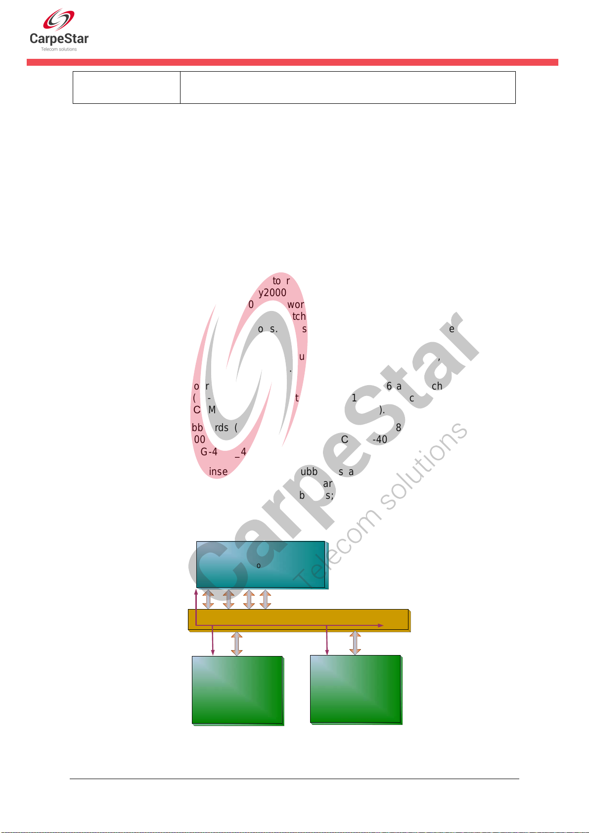
1.1 Typical Application......................................................................................... 1
1.2 Feature List.................................................................................................... 2
1.3 Hardware Description.................................................................................... 2
1.3.1Appearance & Interface Description .........................................................................3
1.3.2Hardware Structure...................................................................................................5
1.4 Alarm Info ...................................................................................................... 6
Chapter 2 Quick Guide ......................................................................7
Chapter 3 WEB Configuration...........................................................9
3.1System Login................................................................................................. 9
3.2Operation Info.............................................................................................. 10
3.2.1 System Info.............................................................................................................10
3.3Gateway Setting ...........................................................................................11
3.3.1Subboard Gateway .................................................................................................11
3.3.2Subboard Configuration..........................................................................................12
3.4Subboard Group.......................................................................................... 12
3.5Route Settings............................................................................................. 13
3.5.1 IP to TEL/PSTN ......................................................................................................14
3.6System Tools ............................................................................................... 16
3.6.1 Network ..................................................................................................................18
3.6.2 Management...........................................................................................................19
3.6.3 IP Routing Table......................................................................................................21
3.6.4 Configuration File....................................................................................................23
3.6.5 Signaling Capture ...................................................................................................24
3.6.6 Signaling Call Track ................................................................................................25
3.6.7 PING Test ...............................................................................................................26
3.6.8 TRACERT Test .......................................................................................................27
3.6.9 Modification Record ................................................................................................28
3.6.10 Backup & Upload ....................................................................................................29
3.6.11 Factory Reset .........................................................................................................29
3.6.12 Upgrade ..................................................................................................................29
3.6.13 Change Password ..................................................................................................30
3.6.14 Restart ....................................................................................................................30
Appendix A Technical Specifications.................................................31
Appendix B Troubleshooting..............................................................32
CUMG Gateway User Manual (Version 1.6.3) Page i

Copyright Declaration
All rights reserved; no part of this document may be reproduced or transmitted in any form or by
any means, electronic or mechanical, without prior written permission from CarpeStar.
CarpeStar in cooperation with Synway Information Engineering Co., Ltd. - hardware and
software developer - reserves all rights to modify this document without prior notice. Please
contact CarpeStar for the latest version of this document before placing an order.
CarpeStar has made every effort to ensure the accuracy of this document but does not
guarantee the absence of errors. Moreover, CarpeStar assumes no responsibility in obtaining
permission and authorization of any third party patent, copyright or product involved in relation
to the use of this document.
CUMG Gateway User Manual (Version 1.6.3) Page iii

Chapter 1Product Introduction
Thank you for choosing CarpeStar CUMG Series Gateway!
The CarpeStar CUMG series gateway products (hereinafter referred to as ‘CUMG gateway’)
integrate the analog, digital and wireless subboards. It can connect the traditional phone
sets, the fax machines, the PSTN and the enterprise PBX as well as the wireless network
to implement multiple features of analog, digital and wireless gateways, providing a
powerful, reliable and cost-effective VoIP solution for such occasions as IP call centers and
multi-branch agencies.
1.1 Typical Application
Figure 1-1 Typical Application
CUMG Gateway
Subscriber
Terminal
IP Phone
Tel TelFax
FXS
LAN
FXO
Internet
E1
Router
FXS
PBX
Tel Tel Tel
E1
SIP
LAN Wireless
Channel
Router
Router
CUMG Gateway
CUMG Gateway
IP Phone
Subscriber
Terminal
IP Phone IP Phone
CUMG Gateway User Manual (Version 1.6.3) Page 1

1.2 Feature List
Basic Features Description
IP Call Call initiated from IP to a designated SIP trunk for voice communication, via routing
and number manipulation.
Number Manipulation Peels off some digits of a phone number from left/right, or adds a prefix/suffix to a
phone number.
VoIP Routing Routing path: from IP to PSTN or from PSTN to IP.
Fax Multiple fax parameters: fax mode, maximum fax rate, fax train mode, error
correction mode, etc.
Echo Cancellation Provides the echo cancellation feature for a call conversation.
IMS Network Registers the gateway to a server under IMS network.
Simultaneous Register
to Multiple Servers Registers the gateway to a master registrar server and a spare registrar server
simultaneously.
Signaling & Protocol Description
SIP Signaling Supported protocol: SIP V1.0/2.0, RFC3261
Voice CODEC G.711A, G.711U, G.729, G723, G722, AMR, iLBC
DTMF Mode RFC2833, SIP INFO, INBAND, RFC2833+Signaling,
In-band+Signaling
Network Description
Network Protocol Supported protocol: TCP/UDP, HTTP, ARP/RARP, DNS, NTP, TFTP, TELNET,
STUN
Static IP IP address modification support
DNS Domain Name Service support
Security Description
Admin Authentication Support admin authentication to guarantee the resource and data security
Maintain & Upgrade Description
WEB Configuration Support of configurations through the WEB user interface
Language Chinese, English
Software Upgrade Support of user interface, gateway service, kernel and firmware upgrades based
on WEB
Tracking Test Support of Ping and Tracert tests based on WEB
SysLog Type Three options available: ERROR, WARNING, INFO
1.3 Hardware Description
The CUMG gateway features 2U rackmount design and integrates embedded LINUX system within
CUMG Gateway User Manual (Version 1.6.3) Page 2

the POWERPC+DSP hardware architecture. It has 2 Megabit Ethernet ports (LAN1 and LAN2) on
the chassis, two fan boxes with removable fans and independent air passages respectively on the
front and back panels.
1.3.1 Appearance & Interface Description
Note: The Internal LAN is only used to access the inserted subboards.
Figure 1-3 Rear View for Uniway2000
Figure 1-4 Left View for Uniway2000
Figure 1-5 Front View for Uniway2100
Ventilation Holes
Screw Holes for
Foot Bracket
CUMG Gateway User Manual (Version 1.6.3) Page 3
Figure 1-2 Front View for Uniway2000
Console Port
FXS Channel Indicator
Run Indicator
Reset Button
Alarm Indicator
FXO Channel Indicator Antenna Interface
RJ45 Interface
USB Interface
VGA Interface
HDD & Run Indicator Kilomega-
Ethernet port
SPK&MIC
Power Switch
220V AC Power
Run Indicator
Console Port
WAN for External
LAN for Internal Reset Button
Power Button
Console Port
Antenna Interface
RJ45 Interface
FXO Channel Indicator
FXS Channel Indicator
Reset Button
Million
Ethernet
Interface

Power Button
220V AC Power
Chassis
Address Code
Figure 1-6 Rear View for Uniway2100
Figure 1-7 Left View for Uniway2100
The table below gives a detailed introduction to the interfaces, buttons and LEDs illustrated
above:
Interface Description
Amount: 2
Type: RJ-45
Bandwidth: 10/100Mbps
Self-Adaptive Bandwidth Supported
LAN
Auto MDI/MDIX Supported
Amount: 1
Type: RS-232
Baud Rate: 115200 bps
Connector: Mini-USB connecting line
Data Bits: 8 bits
Stop Bit: 1 bit
Parity Unsupported
Console Port
Flow Control Unsupported
Button Description
Power Key The power key for the board power supply
Reset Button Restore the gateway to factory settings.
LED Description
Power Indicator Indicates the power state. It lights up when the gateway starts up with the power
cord well connected.
Run Indicator Indicates the running status. For more details, refer to 1.4 Alarm Info.
Alarm Indicator Alarms the device malfunction. For more details, refer to 1.4 Alarm Info.
Link Indicator The green LED on the left of LAN, indicating the network connection status.
Ventilation
Holes Screw Holes for
Foot Bracket
CUMG Gateway User Manual (Version 1.6.3) Page 4

ACT Indicator The orange LED on the right of LAN, whose flashing tells data are being
transmitted.
1.3.2 Hardware Structure
The CUMG gateway features 2U rackmount design, which can be inserted with the CPU board,
the switching board, analog gateway subboards, digital gateway subboards and wireless
gateway subboards. For the Uniway2000 gateway, it designs 6 service board slots in the front,
2 service board slots together with 1 switching board slot at the back. The wider one among
the 9 slots is only for the switching board, and the other 8 slots are optional; for the Uniway2100
gatewaym ut designs 6 service board slots in the front, 1 switching board slot at the back.
The descriptions about the subboards are listed below:
The CPU board (Occupied a height of two service boards) based on the X86 architecture is used
to run the IVR and other programs developed by customers.
The switching board (Uniway2000: CUMG-X08G) based on the MCU03 processor and the
1.2G quad-core ARM processor, is used to run the front-end gateway service program. The
assembled switching board of Uniway2000 has 3 independent Kilomega-Ethernet ports
which can be self-adaptive the 10/100M network. It provides a high-performance, embedded
CPU to manage all the devices. The switching board for Uniway2100 (CUMG-X06)
has 2 independent Million-Ethernet ports. The service boards interact with the exterior via the
switching board.
The digital gateway subboards (CUMG2120) support 1E1, 2E1s and 4E1s, with the type
of CUMG-2030, CUMG-2060 and CUMG-2120.
The analog gateway subboards (CUMG1016) now support up to 16 analog channels, with the
types of CUMG1016-16S (16-channels FXS port), CUMG1016-8S8O (8-channels FXS port and
8-channels FXO port) and CUMG1016-16O (16-channels FXO port).
The wireless gateway subboards (CUMG4008) now support up to 8 wireless channels, with
the type of CUMG-4008_8G, CUMG-4008_8C, CUMG-4008_8W, CUMG-4008_4G,
CUMG-4008_4C and CUMG-4008_4W.
The 8 optional slots can be inserted with any subboards according to your requirement. The
ordinary settings are: 1 CPU board + 1 switching board + 6 available service boards; 2 CPU
boards + 1 switching board + 4 available service boards; 1 switching board + 8 available service
boards.
See the hardware architecture below:
Switching Board
Rear Panel
Figure 1-8 CUMG Gateway Hardware Architecture
LAN LAN
CUMG1016B/
CUMG4008-8G/
CUMG2120
Control
Line Group
CUMG1016B/
CUMG4008-8G/
CUMG2120
CUMG Gateway User Manual (Version 1.6.3) Page 5

1.4 Alarm Info
The CUMG gateway is equipped with two indicators denoting the system’s running status:
Run Indicator (green) and Alarm Indicator (red). The table below explains the states and
meanings of the two indicators.
LED State Description
Go out System is not yet started.
Light up and flash fast System is starting.
Run Indicator
Flash slowly System is normal.
Go out System is normal.
Light up Upon startup: System is normal.
In runtime: System is abnormal.
Alarm Indicator
Flash System is abnormal.
Note:
zThe startup process consists of two stages: System Booting and Gateway Service
Startup. The system booting costs about 1 minute and once it succeeds, both the run
indicator and the alarm indicator light up. Then after the gateway service is successfully
started and the device begins to work normally, the run indicator flashes and the alarm
indicator goes out.
zDuring runtime, if the alarm indicator lights up or flashes, it indicates that the device goes
abnormal. If you cannot figure out and solve the problem by yourself, please contact our
technicians for help. Go to Appendix C Technical/sales Support to find the contact way.
CUMG Gateway User Manual (Version 1.6.3) Page 6

Chapter 2Quick Guide
This chapter is intended to help you grasp the basic operations of the CUMG gateway in
the shortest time.
Step 1: Confirm that your packing box contains all the following things.
z CUMG Gateway *1
zAngle Bracket *2, Rubber Foot Pad *4, Screw for Angle Bracket *8
z220V Power Cord *2
zWarranty Card *1
zInstallation Manual *1
Step 2: Properly fix the CUMG gateway.
If you do not need to place the gateway on the rack, simply fix the 4 rubber foot pads. Otherwise,
you should first fix the 2 angle brackets onto the chassis and then place the chassis on the rack.
Step 3: Connect the power cord.
Make sure the device is well grounded before you connect the power cord. Check if the power
socket has the ground wire.
Note: Each CUMG gateway has two power interfaces to meet the requirement for power supply
hot backup. As long as you properly connect and turn on these two power keys, either power
supply can guarantee the normal operation of the gateway even if the other fails.
Step 4: Connect the network cable.
Step 5: Log in the gateway.
Enter the original IP address (LAN 1: 192.168.1.101 or LAN 2: 192.168.0.101) of the CUMG
gateway in the browser to go to the WEB interface. The original username and password of the
gatewayare both ‘admin’. For detailed instructions about login, refer to 3.1 System Login. We
suggest you change the initial username and password via ‘System Tools ÆChange Password’
on the WEB interface as soon as possible after your first login. For detailed instructions about
changing the password, refer to 3.6.13 Change Password. After changing the password, you are
required to log in again.
Step 6: Modify IP address of the gateway.
You can modify the IP address of the gateway via ‘System Tools ÆNetwork’ on the WEB interface
to put it within your company’s LAN. Refer to 3.6.1 Network for detailed instructions about IP
modification. After changing the IP address, you shall log in the gateway again using your new IP
address.
Step 7: Check the connection of subboards.
After the gateway starts successfully with the subboards, you can go ‘GatewayÆSubboard
Gateway’ on the WEB interface to check if all the subboards are well connected.
Step 8: Set routing rules for calls.
Go to the route setting interface of each subboard to set the routing rules. Please refer to the user
manual of each gateway for detailed information.
Special Instructions:
zThe chassis of the CUMG gateway must be grounded for safety reasons, according to
standard industry requirements. A simple way is earthing with the third pin on the plug.
CUMG Gateway User Manual (Version 1.6.3) Page 7

No or improper grounding may cause instability in operation as well as decrease in
lightning resistance.
zAs the device will gradually heat up while being used, please maintain good ventilation to
prevent sudden failure, ensuring that the ventilation holes (see Figure 1-4) are never
jammed.
zDuring runtime, if the alarm indicator lights up or flashes, it indicates that the device goes
abnormal. If you cannot figure out and solve the problem by yourself, please contact our
technicians for help. Otherwise it may lead to a drop in performance or unexpected
errors.
CUMG Gateway User Manual (Version 1.6.3) Page 8

Chapter 3WEB Configuration
3.1 System Login
Type the IP address into the browser and enter the login interface. See Figure 3-1.
Figure 3-1 Login Interface
The gateway only serves one user, whose original username and password are both ‘admin’. You
can change the username and the password via ‘System Tools ÆChange Password’ on the WEB
interface. For detailed instructions, refer to 3.6.13 Change Password.
After login, you can see the main interface as below.
Figure 3-2 Main Interface
CUMG Gateway User Manual (Version 1.6.3) Page 9

3.2 Operation Info
Operation Info shows the current running status of the gateway. See Figure 3-3.
Figure 3-3 Operation Info
3.2.1 System Info
Figure 3-4 System Info Interface
See Figure 3-4 for the system info interface. You can click Refresh to obtain the latest system
information, click Version Detail to obtain the detailed information of WEB, Gateway, Uboot and
Kernel. The table below explains the items shown in Figure 3-4.
Item Description
MAC Address MAC address of LAN 1 or LAN 2.
CUMG Gateway User Manual (Version 1.6.3) Page 10

IP Address The three parameters from left to right are IP address, subnet mask and default
gateway of LAN 1 or LAN 2.
DNS Server DNS server address of LAN 1 or LAN 2.
Receive Packets,
Transmit Packets
The amount of receive/transmit packets after the gateway’s startup, including three
categories: All, Error and Drop.
Current Speed The current speed of data receiving and transmitting.
Work Mode
The work mode of the network, including six options: 10 Mbps Half Duplex, 10 Mbps
Full Duplex, 100 Mbps Half Duplex, 100 Mbps Full Duplex, 1000 Mbps Full Duplex
and Disconnected.
Note: The mode of 1000 Mbps Full Duplex is unavailable for the Uniway2100
gateway.
Runtime Time of the gateway keeping running normally after startup. This parameter
updates every 2s.
CPU Temperature Display the real time temperature of the CPU.
Serial Number Unique serial number of an CUMG gateway.
WEB Current version of the WEB interface.
Gateway Current version of the gateway service.
Uboot Current version of Uboot.
Kernel Current version of the system kernel on the gateway.
Firmware Current version of the firmware on the gateway.
3.3 Gateway Setting
SIP Settings includes Subboard Gateway and Subboard Configuration. See Figure 3-5.
Figure 3-5 Gateway Settings
3.3.1 Subboard Gateway
The subboard gateway interface displays all the subboard types of the CUMG gateway. See
Figure 3-6. Click Configuration to go to the configuration interface of each subboard. You can
refer to the corresponding gateway’s manual for detailed operations.
CUMG Gateway User Manual (Version 1.6.3) Page 11

Figure 3-6 Subboard Gateway Interface
3.3.2 Subboard Configuration
The subboard configuration interface displays all the route and port information. See Figure 3-7
below.
Figure 3-7 Subboard Configuration Interface
3.4 Subboard Group
Figure 3-8 Subboard Group Settings
See Figure 3-8 for the subboard group setting interface. A new subboard group can be added by
the Add New button on the bottom right corner of the list in the above figure. See Figure 3-9 for
the subboard group adding interface.
Figure 3-9 Add New Subboard Group
The table below explains the items shown in Figure 3-9.
CUMG Gateway User Manual (Version 1.6.3) Page 12

Item Description
Index The unique index of each subboard group, which is mainly used in the configuration
of routing rules and number manipulation rules to correspond to subboard groups.
Description More information about each subboard group.
Subboards
The subboards in the subboard group. If the checkbox before a subboard is grey, it
indicates that the subboard has been occupied. The ticked subboards herein will be
displayed in the column ‘Subboards’ in Figure 3-8.
After configuration, click Save to save the settings into the gateway or click Close to cancel the
settings.
Click Modify in Figure 3-8 to modify a subboard group. See Figure 3-10 for the subboard group
modification interface. The configuration items on this interface are the same as those on the Add
New Subboard Group interface.
Figure 3-10 Modify Subboard Group
To delete a subboard group, check the checkbox before the corresponding index in Figure 3-8
and click the Delete button. Check All means to select all available items on the current page;
Uncheck All means to cancel all selections on the current page; Inverse means to uncheck the
selected items and check the unselected. To clear all subboard groups at a time, click the Clear
All button in Figure 3-8.
3.5 Route Settings
Route Settings is used to specify the routing rules for calls from IP to TEL/PSTN. See Figure 3-11.
Figure 3-11 Route Settings
CUMG Gateway User Manual (Version 1.6.3) Page 13

3.5.1 IP to TEL/PSTN
By default, there is no IPÆTEL/PSTN routing rule available on the gateway. Click Add New to
add some manually. See Figure 3-12 for the IPÆTEL/PSTN routing rule adding interface.
Figure 3-12 Add New Routing Rule (IPÆTEL/PSTN)
The table below explains the items shown in the above figure.
Item Description
Index
The unique index of each routing rule, which denotes its priority. A routing rule with
a smaller index value has a higher priority. If a call matches several routing rules, it
will be processed according to the one with the highest priority.
Source IP The IP address where the calls come from.
CUMG Gateway User Manual (Version 1.6.3) Page 14

CallerID Prefix,
CalleeID Prefix
A string of numbers at the beginning of the calling/called party number. This item
can be set to a specific string or “*” which indicates any string. These two
configuration items together with Call Initiator can specify the calls which apply to a
routing rule.
Rule Explanation:
Character Description
“0”~”9” Digits 0~9.
“[ ]”
‘[ ]’ is used to define the range for a number. Values within it only
can be digits ‘0~9’, punctuations ‘-’ and ‘,’. For example,
[1-3,6,8] indicates any one of the numbers 1, 2, 3, 6, 8.
“-” ’-’ is used only in ‘[ ]’ between two numbers to indicates any
number between these two numbers.
“,” ’,’ is used to separate numbers or number ranges, representing
alternatives.
Example: Rule “0[0-3,7][6-9]” denotes the prefix is 006, 016, 026, 036, 007, 017,
027, 037, 008, 018, 028, 038, 009, 019, 029, 039, 076, 077, 078, 079.
Note: Multiple rules are supported for CallerID/CalleeID prefix. They are separated
by “:”.
Call Destination Subboard group to which the call will be routed.
Description More information about each routing rule.
After configuration, click Save to save the settings into the gateway or click Close to cancel the
settings. See Figure 3-13 for the IPÆTEL/PSTN Routing Rule Configuration Interface.
Figure 3-13 IPÆTEL/PSTN Routing Rule Configuration Interface
Click Modify in Figure 3-13 to modify a routing rule. See Figure 3-14 for the IPÆTEL/PSTN
routing rule modification interface. The configuration items on this interface are the same as those
on the Add New Routing Rule (IP
Æ
TEL/PSTN) interface. Note that the item Index cannot be
modified.
CUMG Gateway User Manual (Version 1.6.3) Page 15
This manual suits for next models
2
Table of contents
Other CarpeStar Gateway manuals
Popular Gateway manuals by other brands

Yeastar Technology
Yeastar Technology NeoGate TA FXS Quick installation guide

AddPac
AddPac VoiceFinder AP2620 installation guide

THOMSON
THOMSON 905 user manual

HMS Networks
HMS Networks Intesis IN770AIR00 O000 Series user manual

IKEA
IKEA tradfri manual

Edgewater Networks
Edgewater Networks ATT110900764 Replacement guide

VBOX
VBOX XTi-4134 Quick installation

Tadiran Telecom
Tadiran Telecom TGW1E1-2G User configuration guide

CONTROL SOLUTIONS
CONTROL SOLUTIONS Babel Buster 3 BB3-6101-GW user guide

turck
turck BL20-E-GW-EC Instructions for use

ZyXEL Communications
ZyXEL Communications P-2301R/RL-P1C Support notes

Wiznet
Wiznet WIZ6000 user manual