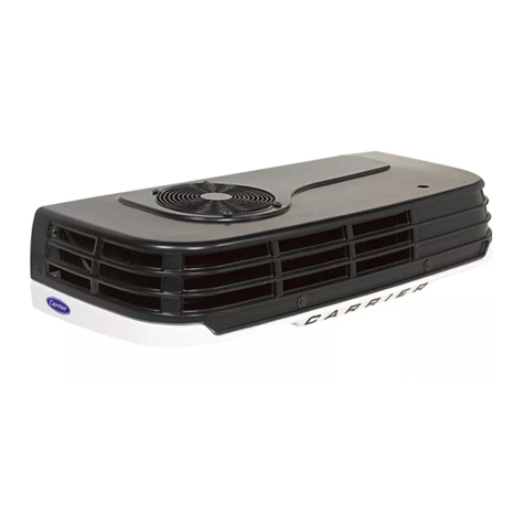
Carrier TRANSICOLD Neos 100S User manual

FPO
Operator’s Manual
62-11850
Rev C
TM
Neos 100S
Truck Refrigeration Units


OPERATOR’S MANUAL
For The
Neos 100S
Truck Refrigeration Units
© 2020 Carrier Corporation ●Printed in USA April 2020
TM


62-11850
TABLE OF CONTENTS
INTRODUCTION . . . . . . . . . . . . . . . . . . . . . . . . . . . . . . . . . . . 1
UNIT IDENTIFICATION . . . . . . . . . . . . . . . . . . . . . . . . . . . . . 2
SAFETY . . . . . . . . . . . . . . . . . . . . . . . . . . . . . . . . . . . . . . . . . 3
UNIT OPERATION . . . . . . . . . . . . . . . . . . . . . . . . . . . . . . . . . 4
DISPLAY . . . . . . . . . . . . . . . . . . . . . . . . . . . . . . . . . . . . . . . . . 5
STARTING THE UNIT . . . . . . . . . . . . . . . . . . . . . . . . . . . . . . 7
STOPPING THE UNIT . . . . . . . . . . . . . . . . . . . . . . . . . . . . . . 8
TEMPERATURE SET POINT . . . . . . . . . . . . . . . . . . . . . . . . . 9
MANUAL DEFROST . . . . . . . . . . . . . . . . . . . . . . . . . . . . . . . 10
DEFROST INTERVAL . . . . . . . . . . . . . . . . . . . . . . . . . . . . . 11
MINIMUM SET POINT LOCK . . . . . . . . . . . . . . . . . . . . . . . . 12
DISPLAYING UNIT DATA . . . . . . . . . . . . . . . . . . . . . . . . . . . 14
PRODUCT LOADING . . . . . . . . . . . . . . . . . . . . . . . . . . . . . . 15
RECOMMENDED TRANSPORT TEMPERATURES . . . . . . 17
GENERAL TROUBLESHOOTING . . . . . . . . . . . . . . . . . . . . 18
ALARM DESCRIPTION . . . . . . . . . . . . . . . . . . . . . . . . . . . . 20
ALARM LIST AND ALARM RESET . . . . . . . . . . . . . . . . . . . 21
FUSES . . . . . . . . . . . . . . . . . . . . . . . . . . . . . . . . . . . . . . . . . 22
UNIT MAINTENANCE . . . . . . . . . . . . . . . . . . . . . . . . . . . . . . 23
STANDBY OPERATION GUIDELINES . . . . . . . . . . . . . . . . 25
EMERGENCY ROAD SERVICE . . . . . . . . . . . . . . . . . . . . . . 26

62-11850

1 62-11850
INTRODUCTION
This guide has been prepared for the operator of Carrier Transicold’s
NeosTM 100S battery driven refrigeration units with Cab Command
controller. It contains basic instructions for the daily operation of the
refrigeration unit as well as safety information, and other information that
will help to deliver the load in the best possible condition. Please take the
time to read the information contained in this booklet and refer to it
whenever there is a question about the operation of this Carrier
Transicold truck refrigeration unit.
This refrigeration unit has been engineered to provide long, trouble-free
performance when it is properly operated and maintained. A
comprehensive maintenance program will help to ensure that the unit
continues to operate reliably. Such a maintenance program will also help
to control operating costs, increase the unit’s working life, and improve
performance.
This guide is intended as an introduction to the unit and to provide general
assistance when needed. More comprehensive information can be found
in the Operation and Service Manual for this unit, which can be obtained
from a Carrier Transicold dealer.
When having a unit serviced, be sure to specify genuine Carrier
Transicold replacement parts for the highest quality and best reliability.
At Carrier Transicold, we are continually working to improve the products
that we build for our customers. As a result, specifications may change
without notice.

62-11850 2
UNIT IDENTIFICATION
Each unit is identified by a nameplate attached to the frame of the unit.
The nameplate identifies the complete model number of the unit, the
serial number and some other information.
If a problem occurs, please refer to the information on this plate, and
make a note of the model and serial number before calling for assistance.
This information will be needed when contacting a technician so that they
may properly assist you.
The complete nameplate is fixed on the frame and the Serial Number is
fixed on the pod.
Nameplate Location
Nameplate

3 62-11850
SAFETY
WARNING
!
Use proper Lockout/Tagout procedures before inspect-
ing/servicing this unit. All unit inspection/servicing
must be performed by properly trained personnel only.
This Carrier Transicold refrigeration unit has been designed with the
safety of the operator in mind. During normal operation, all moving parts
are fully enclosed to help prevent injury. During all pre-trip inspections,
daily inspections, and problem troubleshooting, you may be exposed to
moving parts; please stay clear of all moving parts when the unit is in
operation.
WARNING
!
Beware of unannounced starting of the fans caused by
the thermostat and the start/stop cycling of the unit.
Refrigerants
The refrigerant contained in the unit refrigeration system can cause
frostbite, severe burns, or blindness when in direct contact with the skin or
eyes. For this reason, and because of legislation regarding the handling
of refrigerants during system service, we recommend that whenever the
unit requires service of the refrigeration system you contact the nearest
Carrier Transicold authorized repair facility for service.
WARNING
!
Inspect battery cables for signs of wear, abrasion or
damage at every pre trip inspection and replace if neces-
sary. Also check battery cable routing to ensure that
clamps are secure and that cables are not pinched or
chafing against any components.

62-11850 4
UNIT OPERATION
The Neos 100S is an all-electrical unit, powered by the vehicle battery
(alternator).
After starting up the refrigeration unit by pressing the ON key, the
microprocessor manages the unit regulation according to the box
temperature needed.
The unit automatically shuts down when the engine is switched off with
the ignition key.
The unit can be completely shut down manually by pressing the OFF key
on the Cab Command.
Standby Mode
The Neos 100S is powered by a standby module reducing the 230 VAC
into 12 Vdc. The power network connection is detected by the standby
module which automatically starts up the unit in standby mode.
If the ignition key is switched ON while the unit is connected to the power
network, or if the standby plug is connected while the unit is running, a
buzzer alarm will sound indicating the double power supply and the unit
stops.
Temperature Control
As soon as the set point temperature has been reached, temperature
control is obtained by shutdown and start-up of the electro-magnetic
clutch.
The condenser and evaporator fans cut out during regulation. When
transporting fragile loads such as fresh meat, vegetables and cheese, it is
possible to program the microprocessor to obtain continuous ventilation
by the evaporator during regulation.
Defrost
Defrost operation is fully automatic but can be manually controlled.
• Defrost cycles are fully controlled by the integrated microprocessor.
• During the defrost cycle, the evaporator fan shuts down. The con-
denser fan is controlled by the microprocessor.
• Defrost cycle termination is controlled by a defrost thermostat.
• During the defrost cycle, the cab command display indicates "dF".

62-11850 6
DISPLAY - CONTINUED
Display - 3 digits
• Box temperature
• "dF" message in defrost mode
• Malfunction messages
• Software version
• Hourmeter value
• Configuration parameters in the different menus
ON / OFF keys
These keys are for starting and stopping the unit.
SET key
This key is for accessing set point and unit data. This key will also allow
the user to enter into the Selection menu for the functional and defrost
parameters when combined with other keys.
MINUS & PLUS keys
These keys are for selecting the requested settings in different menus.
DEFROST key
This key enables manual defrost control.
°C / °F LED
This indicates that the unit is running and if temperature is displayed in
Celsius or Fahrenheit degrees.
REGULATION LED - Green
This indicates the three different modes:
• COOLING mode: green light is ON.
• NULL mode (regulation): green light is OFF.
• HEATING mode: green light flashing.
ALARM LED - Red
This LED will flash in case of a malfunction.

7 62-11850
STARTING THE UNIT
1. Start the vehicle engine.
2. Start the unit by pressing the ON key. Start-up is time-delayed for
30 seconds.
3. The digital display of the Cab Control displays the box temperature.
4. Check that the temperature set point is correct by pressing the SET
key. The set point temperature is highlighted on the digital display.
5. Enter a new set point if necessary.
2
4
3

62-11850 8
STOPPING THE UNIT
1. For a delivery stop: turn the unit off by the vehicle ignition key.
2. For a long stop (more than 2 hours): press the OFF key.
2

9 62-11850
TEMPERATURE SETPOINT
NOTE
If, when settings are adjusted, no key is activated within
five seconds, the system reverts to displaying the box
tempera-ture. All changes made are recorded.
1. Press the SET key to display the setpoint temperature.
2. Press the + or - key to change the setpoint.
3. Press the SET key to return to the box temperature display.
1, 3
22

62-11850 10
MANUAL DEFROST
1. Check the display to verify that the box temperature is 40°F or
lower.
2. Press the Defrost key to initiate manual defrost.
1
2

11 62-11850
DEFROST INTERVAL
NOTE
If, when settings are adjusted, no key is activated within
five seconds, the system reverts to displaying the box
tempera-ture. All changes made are recorded.
1. Press the OFF key to shut down the unit.
2. Press simultaneously the Defrost and ON keys and hold for
five seconds to display the last selected defrost interval.
3. Press the + or - key to change the defrost interval.
• 00: Inhibit Defrost Function.
•AUT (coefficient 1): microprocessor-optimized automatic defrost
according to type of cargo transported (variable intervals).
• 1H, 2H,.....6H: Fixed defrost interval in hours.
4. Press the SET key to return to the box temperature display.
1
2
2
33
4

62-11850 12
MINIMUM SETPOINT LOCK
To limit the temperature pull-down, it is possible to program the minimum
set point lock:
1. Press consecutively the +, - and Defrost keys to access the
functional parameters.
2. The display will show the previous Minimum Setpoint Lock value.
• Available values are: 32°F / -4°F / -20°F
•Factory setting by default: 32°F
3.
Press the + or - key to modify the displayed value.
4. Press the SET key to validate the new selected value.
5. The display will show the Differential Parameter value.
• Available values are: 32°F / -4°F / -20°F
•Factory setting by default: 32°F
6. Press + or - key to modify the displayed value.
7. Press the SET key to validate the new selected value.
1
1,3,6 1,3,6
4,7

13 62-11850
MINIMUM SETPOINT LOCK - CONTINUED
8. The display will show the EFM (Evaporator Fan Motor) status in
“Null” Mode.
• Available values are: ON or OFF
• Factory setting by default: OFF
9. Press the + or - key to modify the displayed value.
10.Press the SET key to validate the new selected value and return to
the box temperature display.

62-11850 14
DISPLAYING UNIT DATA
1. Press the SET key for five seconds to enable access to
malfunction codes.
2. Press the + or - key to display active or passive alarms.
3. Press the SET key to display the software version.
4. Press the SET key to display the hourmeter.
5. Press the SET key to return to the box temperature display.
22
1, 3, 4, 5
Table of contents
Other Carrier TRANSICOLD Automobile Accessories manuals
Popular Automobile Accessories manuals by other brands

WaterDog Adventure Gear
WaterDog Adventure Gear WAG Boarding Steps FS-6 owner's manual

Ecco
Ecco Vantage 12 Series Installation and operation instructions

AlienTech
AlienTech K-TAG Master Instruction manual and users guide

DFI
DFI VP101-BT user manual

Whispbar
Whispbar K638 manual

Allen Sports
Allen Sports S102 instructions