Carrier 48FP Operating instructions

Manufacturer reserves the right to discontinue, or change at any time, specifications or designs without notice and without incurring obligations.
PC 111 Catalog No. 534-738 Printed in U.S.A. Form 48/50F,J-2T Pg 1 7-99 Replaces: 48/50F,J,N-1T
Book 1 1
Tab 1a 1b
Controls Operation and Troubleshooting
CONTENTS
Page
SAFETY CONSIDERATIONS. . . . . . . . . . . . . . . . . . . . . . 2
GENERAL . . . . . . . . . . . . . . . . . . . . . . . . . . . . . . . . . . . . . . 2-4
Carrier Comfort Network System
Architecture. . . . . . . . . . . . . . . . . . . . . . . . . . . . . . . . . . . . 2
PIC Rooftop Information. . . . . . . . . . . . . . . . . . . . . . . . . . 4
Digital Air Volume (DAV) Linkage. . . . . . . . . . . . . . . . . 4
MAJOR CONTROL COMPONENTS . . . . . . . . . . . . . 4-8
General. . . . . . . . . . . . . . . . . . . . . . . . . . . . . . . . . . . . . . . . . . . 4
• PROCESSOR MODULE NO . 1 (Standard)
• CONTROL OPTIONS MODULE
• HIGH-VOLTAGE RELAY MODULES (DSIO1 AND
DSIO2)
• KEYPAD AND DISPLAY MODULE (HSIO)
• ECONOMIZER ACTUATORS
• VARIABLE FREQUENCY DRIVES
• INLET GUIDE VANES
• MODULATING POWER EXHAUST
• THERMISTORS AND REFRIGERANT PRESSURE
TRANSDUCERS
• FAN STATUS PRESSURE SWITCH
• CHECK FILTER PRESSURE SWITCH
Optional and Accessory Control
Components . . . . . . . . . . . . . . . . . . . . . . . . . . . . . . . . . . . 6
• SPACE TEMPERATURE SENSOR (T-55)
• SPACE TEMPERATURE SENSOR (T-56)
• RELATIVE HUMIDITY (RH) SENSORS
• INDOOR AIR QUALITY (CO2) SENSORS
• OUTDOOR AIR VOLUME CONTROL
• HUMIDIFIER DEVICES
• HYDRONIC COIL AND CONTROL VALVE
CONTROLS AND FUNCTIONS. . . . . . . . . . . . . . . . . 8-34
Definitions . . . . . . . . . . . . . . . . . . . . . . . . . . . . . . . . . . . . . . . 8
Accessing the Control System
(HSIO). . . . . . . . . . . . . . . . . . . . . . . . . . . . . . . . . . . . . . . . . . 9
• KEYPAD AND DISPLAY MODULE (HSIO)
• STANDBY/RUN MODE
• SUMMARY DISPLAY
• ACCESSING FUNCTIONS AND SUBFUNCTIONS
• OPERATING MODE DISPLAY
• LOGON AND LOGOFF/PASSWORD
•DATARESET
• CHANGING DISPLAY FOR METRIC UNITS
Basic System Functions . . . . . . . . . . . . . . . . . . . . . . . . 12
•BASICSYSTEMS
•STANDBY
• SUPPLY FAN
• COOLING
• HEATING
Service Group. . . . . . . . . . . . . . . . . . . . . . . . . . . . . . . . . . . 16
• ALERTS AND ALARMS
• QUICK TEST
Schedules Group. . . . . . . . . . . . . . . . . . . . . . . . . . . . . . . . 18
• TIME SCHEDULES
Page
• TIMED DISCRETE OUTPUT
• TIMED OVERRIDE
•OPTIMALSTART
• OPTIMAL STOP (CV Units Only)
Economizer and Power Exhaust Group. . . . . . . . . . 20
•ECONOMIZER
• NIGHTTIME/UNOCCUPIED FREE COOLING
• MODULATING POWER EXHAUST
Smoke Control Group . . . . . . . . . . . . . . . . . . . . . . . . . . . 24
• PRESSURIZATION
•EVACUATION
• SMOKE PURGE
• FIRE SHUTDOWN
Special Ventilation Group . . . . . . . . . . . . . . . . . . . . . . . 25
• INDOOR AIR QUALITY (IAQ)
• IAQ (Pre-Occupancy) PURGE
• OUTDOOR AIR CONTROL (OAC)
• IAQ/OAQ REHEAT
Dehumidification and Humidifier Group . . . . . . . . . 28
• DEHUMIDIFICATION AND REHEAT
• HUMIDIFIER CONTROL
Supply Fan Duct Pressure and
VAV Control Group . . . . . . . . . . . . . . . . . . . . . . . . . . . . 29
• SUPPLY FAN DUCT PRESSURE CONTROL
(VAV Only)
• SUPPLY-AIR SET POINT RESET FROM
SPACE TEMPERATURE (VAV Units Only)
• SUPPLY-AIR SET POINT RESET
(External Signal)
Remote Controls Group . . . . . . . . . . . . . . . . . . . . . . . . . 31
• REMOTE START
• SPACE TEMPERATURE OFFSET (CV Only)
Special Systems Group . . . . . . . . . . . . . . . . . . . . . . . . . 31
• HYDRONIC HEATING
• FREEZESTAT
• LEAD/LAG OPERATION
• HEAD PRESSURE/FAN CYCLING CONTROL
(Motormaster® Head Pressure Control)
• TRANSDUCERS AND SUCTION THERMISTORS
Carrier Comfort Network (CCN) Group . . . . . . . . . . 33
• DEMAND LIMIT
• DIGITAL AIR VOLUME (DAV)
INSTALLATION INFORMATION . . . . . . . . . . . . . . . 34-43
Control Wiring. . . . . . . . . . . . . . . . . . . . . . . . . . . . . . . . . . . 34
Smoke Control . . . . . . . . . . . . . . . . . . . . . . . . . . . . . . . . . . 34
Heat Interlock Relay (HIR)
Function Wiring. . . . . . . . . . . . . . . . . . . . . . . . . . . . . . . 35
Remote SASP Reset. . . . . . . . . . . . . . . . . . . . . . . . . . . . . 35
Remote START/OCCUPIED Control. . . . . . . . . . . . . . 35
Timed Discrete Output . . . . . . . . . . . . . . . . . . . . . . . . . . 41
Air Pressure Tubing . . . . . . . . . . . . . . . . . . . . . . . . . . . . . 41
Space Temperature Sensors . . . . . . . . . . . . . . . . . . . . 41
Humidity Sensors . . . . . . . . . . . . . . . . . . . . . . . . . . . . . . . 41
48FP,JP,NP034-074
50FB,FP,JB,JP,NB,NP034-104
Single-Package Heating/Cooling Units
With Product Integrated Controls
50/60 Hz

2
CONTENTS (cont) Page
CARRIER COMFORT NETWORK
INTERFACE . . . . . . . . . . . . . . . . . . . . . . . . . . . . . . . . 43-45
RJ-11 Plug Wiring . . . . . . . . . . . . . . . . . . . . . . . . . . . . . . . 44
Monitor and/or Control from Non-CCN
Building Management System. . . . . . . . . . . . . . . . . 44
START-UP . . . . . . . . . . . . . . . . . . . . . . . . . . . . . . . . . . . . 46-61
Initial Check. . . . . . . . . . . . . . . . . . . . . . . . . . . . . . . . . . . . . 46
Set Fan Status and Check Filter Switches . . . . . . . 46
• SUPPLY FAN STATUS SWITCH (FS)
• CHECK FILTER SWITCH (CFS)
Auxiliary Switch, Power Exhaust . . . . . . . . . . . . . . . . 46
Adjusting Set Points. . . . . . . . . . . . . . . . . . . . . . . . . . . . . 47
• SET POINT FUNCTION
Program Time Sequences . . . . . . . . . . . . . . . . . . . . . . . 52
• SCHEDULE FUNCTION
Start Unit. . . . . . . . . . . . . . . . . . . . . . . . . . . . . . . . . . . . . . . . 53
Operating Sequences . . . . . . . . . . . . . . . . . . . . . . . . . . . 53
Head Pressure Control . . . . . . . . . . . . . . . . . . . . . . . . . . 56
Control Loop Checkout. . . . . . . . . . . . . . . . . . . . . . . . . . 60
UNIT OPERATION . . . . . . . . . . . . . . . . . . . . . . . . . . . . 61-70
Status Function . . . . . . . . . . . . . . . . . . . . . . . . . . . . . . . . . 61
TROUBLESHOOTING. . . . . . . . . . . . . . . . . . . . . . . . . 71-87
Checking Display Codes . . . . . . . . . . . . . . . . . . . . . . . . 71
Unit Standby . . . . . . . . . . . . . . . . . . . . . . . . . . . . . . . . . . . . 71
Complete Unit Stoppage . . . . . . . . . . . . . . . . . . . . . . . . 71
Single Circuit Stoppage . . . . . . . . . . . . . . . . . . . . . . . . . 72
Restart Procedure. . . . . . . . . . . . . . . . . . . . . . . . . . . . . . . 72
Alarm and Alerts . . . . . . . . . . . . . . . . . . . . . . . . . . . . . . . . 72
• DIAGNOSTIC ALARM CODES AND
POSSIBLE CAUSES
Thermistor Troubleshooting. . . . . . . . . . . . . . . . . . . . . 76
Transducer Troubleshooting. . . . . . . . . . . . . . . . . . . . . 80
Refrigerant Pressure Transducer
Replacement and Calibration. . . . . . . . . . . . . . . . . . 80
Control Modules. . . . . . . . . . . . . . . . . . . . . . . . . . . . . . . . . 81
• PROCESSOR MODULE (PSIO1), CONTROL
OPTION MODULE (PSIO2), AND HIGH-VOLTAGE
RELAY MODULES (DSIO1 AND DSIO2)
• RED LED
• GREEN LED
• PROCESSOR MODULE (PSIO1)
• HIGH-VOLTAGE RELAY MODULES
(DSIO1 AND 2)
• CONTROL OPTIONS MODULE (PSIO2)
• ACTUATORS
Economizer Actuator. . . . . . . . . . . . . . . . . . . . . . . . . . . . 84
Variable Frequency Drive. . . . . . . . . . . . . . . . . . . . . . . . 84
Quick Test. . . . . . . . . . . . . . . . . . . . . . . . . . . . . . . . . . . . . . . 86
Forcing Values . . . . . . . . . . . . . . . . . . . . . . . . . . . . . . . . . . 87
SERVICE . . . . . . . . . . . . . . . . . . . . . . . . . . . . . . . . . . . . 87-102
History Function . . . . . . . . . . . . . . . . . . . . . . . . . . . . . . . . 87
Service Function . . . . . . . . . . . . . . . . . . . . . . . . . . . . . . . . 87
Test Function. . . . . . . . . . . . . . . . . . . . . . . . . . . . . . . . . . . . 96
Unit Control Wiring. . . . . . . . . . . . . . . . . . . . . . . . . . . . . . 96
Appendix A — Input/Output
Tables 034-078 . . . . . . . . . . . . . . . . . . . . . . . . . . . 103,104
Appendix B — Input/Output
Tables 088,104 . . . . . . . . . . . . . . . . . . . . . . . . . . . 105,106
Appendix C — CCN Points List. . . . . . . . . . . . . 107,108
Appendix D — Bacnet Points List . . . . . . . . . . 109,110
Appendix E — Carrier Default Program
Parameter Values . . . . . . . . . . . . . . . . . . . . . . . . . . . . 111
START-UP CHECKLIST . . . . . . . . . . . . . . . . .CL-1 to CL-4
SAFETY CONSIDERATIONS
Installing, starting up, and servicing this equipment can be
hazardous due to system pressures, electrical components; and
equipment location (roof, elevated structures, etc.). Only
trained, qualified installers and service mechanics should in-
stall, start up, and service this equipment
When working on this equipment, observe precautions in
the literature; on tags, stickers, and labels attached to the equip-
ment, and any other safety precautions that apply. Follow all
safety codes. Wear safety glasses and work gloves. Use care in
handling, rigging, and setting this equipment, and in handling
all electrical components.
GENERAL
This Controls and Troubleshooting book includes the fol-
lowing units and sizes:
• 48FP034-074
• 48JP034-064
• 48NP034-074
• 50FB034-104
• 50FP034-074
• 50FPX,FPY034-104 (extended plenum units)
• 50JB034-064
• 50JP034-074
• 50JPX,JPY034-064 (extended plenum units)
• 50NB034-074
• 50NP034-074
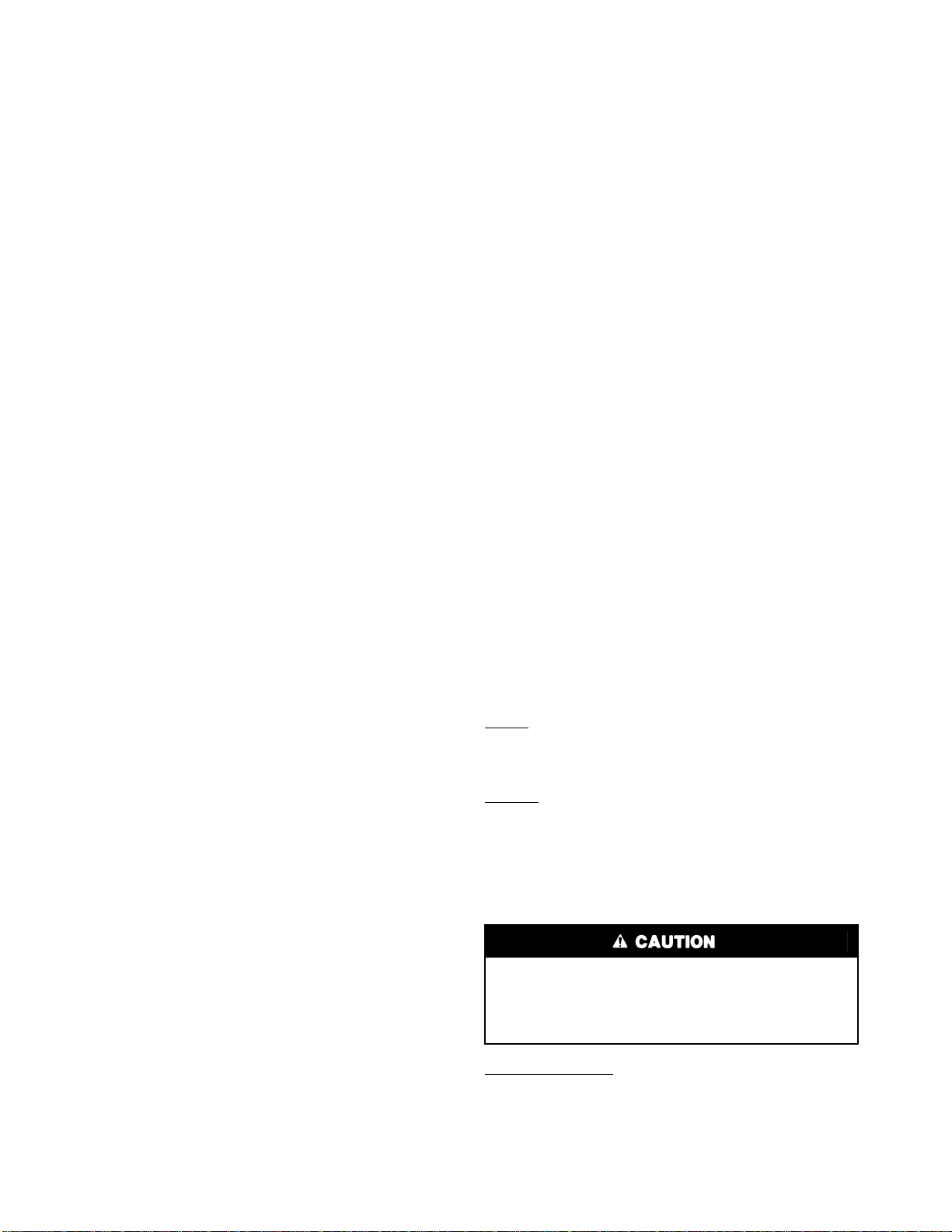
All units have Product Integrated Controls (PIC).
Carrier Comfort Network System Architecture
(Fig. 1)
These units provide ventilation, cooling, and heating (when
equipped) in Variable Air Volume (VAV) and Constant Volume
(CV) applications. The 48FP,JP,NP and 50FB,FP,JB,JP,NB,NP
units contain factory-installed Product Integrated Controls
(PIC) which provide full system management. Processor mod-
ules (PSIO) store hundreds of configuration settings and sever-
al building schedules. The PSIOs also perform self diagnostic
tests at unit start-up, monitor operation of the unit, and provide
alarms. Information on system operation and status are sent to
the central processors by various sensors that are located at the
unit and in the conditioned space. Access to the unit controls
for configuration, set point selection, schedule creation, and
service can be done through a unit-mounted keypad and dis-
play module (HSIO) which is available as an accessory. One
HSIO is required for each installation site. A separate HSIO
may be purchased for each unit, or a single HSIO may be
moved and installed on each unit as required. An HSIO may be
unit mounted or remotely located.
Electrical shock can cause personal injury and death. Shut
off all power to this equipment during installation and ser-
vice. There may be more than one disconnect switch. Tag
all disconnect locations to alert others not to restore power
until work is completed.
This unit uses a microprocessor-based electronic control
system. Do not use jumpers or other tools to short out com-
ponents, or to bypass or otherwise depart from recom-
mended procedures. Any short-to-ground of the control
board or accompanying wiring may destroy the electronic
modules or electrical components.
IMPORTANT: This literature contains controls,
operation, and troubleshooting data for 48FP,JP,NP
and 50FB,FP,JB,JP,NB,NP rooftop units. Use this
guide in conjunction with the separate Installation
Instructions literature packaged with the unit.

3
NETWORK
OPTIONS
REMOTE
CCN SITE AUTODIAL
GATEWAY
NON CARRIER
HVAC
EQUIPMENT
TERMINAL
SYSTEM
MANAGER
TCU
ROOFTOP
UNIT DAV AIR
TERMINAL
TCU TCU
DAV AIR
TERMINAL
AIR DISTRIBUTION-DIGITALAIR VOLUME CONTROL (DAV)
DAV FAN
POWERED
MIXING
BOX
TO
ADDITIONAL
TERMINALS
HEATING/COOLING UNITS
BUILDING SUPERVISOR
ROOFTOP
UNIT
PIC
ROOFTOP
UNIT
PIC
ROOFTOP
UNIT
PIC
ROOFTOP
UNIT
PIC
CCN BUS
PIC
COMFORT
CONTROLLER
LEGEND
CCN — Carrier Comfort Network
DAV — Digital Air Volume
HVAC — Heating, Ventilation, and Air Conditioning
PIC — Product Integrated Controls
TCU — Terminal Control Unit
Fig. 1 — CCN System Architecture

4
The PIC units can operate either in a stand-alone mode or
they can be interfaced with the Carrier Comfort Network
(CCN). When being installed in network applications, the unit
is connected to the CCN communications bus with field-
installed cable.
Other equipment can also be installed on the CCN by fitting
the equipment with a Comfort Controller Device. The Comfort
Controller Device has a standard processor module (PSIO) but
is field-programmed for use with other HVAC components.
Heating, ventilation and air conditioning (HVAC) and other
building equipment being controlled by PICs or Comfort
Controller Device have the inherent ability to ‘talk’ on a com-
mon communications bus or network. The configuration of
the communications bus with 2 or more PIC- or Comfort
Controller-controlled pieces of equipment is referred to as a
Carrier Comfort Network (CCN) system. The CCN communi-
cations bus conveys commands, data, and alarms between all
elements of the system. Any system element connected to the
bus may communicate with any other system element, regard-
less of their physical locations. The communications bus con-
sists of a field-supplied, shielded, 3-conductor cable connected
in daisy-chain fashion. The PICs, Comfort Controllers, and
other network devices (such as TELink) can be added at any
time to the network.
The main human interface with the CCN system is the
ComfortWORKS® software. The ComfortWorks software is
installed on an IBM PC compatible computer that allows it to
connect to the communications bus and ‘talk’ directly with any
equipment connected to the network. An operator working
with ComfortWORKS software can command, monitor, con-
figure, or modify any portion of the system. More than one
computer with ComfortWORKS software can be used. The
computer with ComfortWORKS software, in conjunction with
optional network products, can generate a wide variety of man-
agerial reports which reflect the operational characteristics of
one or more buildings.
To take further advantage of the network, accessory or op-
tional control options modules that perform specialized func-
tions can be added to the communications bus at any time to
enhance the CCN system’s capabilities. Each control options
module consists of a standard hardware module with special
purpose algorithms and communications software that provide
an advanced control function for the entire CCN system or a
designated portion of the system. Data collection, remote com-
munications, demand limiting, and tenant billing are a few ex-
amples of the network capabilities available to give the build-
ing owner increased system performance and superior building
management capabilities.
Zoned systems meet the zone temperature control needs for
many commercial applications. These systems utilize a micro-
electronic thermostat as a basis for individual zone control and
typically build multiple-zone systems with constant volume
(CV) or variable-air volume (VAV) units. Zoned systems can
provide complete control of heating and cooling equipment
and zone dampers in many types of HVAC systems.
PIC Rooftop Information — The PIC rooftop con-
trols cycle supply-fan motor, compressors, and unloaders to
maintain the proper temperature conditions. The controls also
cycle condenser fans to maintain suitable head pressure. Safe-
ties are continuously monitored to prevent the unit from operat-
ing under abnormal conditions. The controls provide control of
economizer, power exhaust, and inlet guide vane actuators or
variable frequency drives, and cycle or control heating as
required.
A scheduling function, programmed by the user, controls
the unit occupied/unoccupied schedule. The controls also allow
the service person to operate a ‘quick test’ so that all the con-
trolled components can be checked for proper operation.
The PIC controls are modular and use a processor module
(PSIO1), 2 relay modules (DSIO1 and DSIO2), a control op-
tions module (PSIO2), and an accessory field-installed keypad
and display module (HSIO).
Digital Air Volume (DAV) Linkage — Carrier roof-
top units with PIC may also have a communication linkage
with the VAV terminal units in a particular application. This
linkage is called the DAV linkage. In order for this linkage to
be possible, the individual VAV air terminals must be equipped
with Carrier PIC controls and the air terminals must be linked
by a Terminal System Manager (TSM). The TSM acts as the
communication link between the VAV air terminal PICs and
the rooftop unit. When the TSM is fully programmed and be-
gins communication, the rooftop control begins using informa-
tion from the TSM for rooftop unit control operation. This is
automatic, and does not require a configuration change to the
standard rooftop unit PIC.
MAJOR CONTROL COMPONENTS
General — The control system consists of the following
components (see Fig. 2):
• standard processor module (PSIO 8088 or PSIO1)
• control options module (PSIO 8052 or PSIO2) (option
and accessory on sizes 034-074, standard on sizes 078-
104)
• two standard high-voltage relay modules (DSIO1 and
DSIO2)
• keypad and display module (HSIO) (accessory)
• enthalpy sensor
• thermistors (standard and accessory)
• pressure transducers (standard and accessory)
• accessory humidity sensors
• space temperature sensors (standard T-55 and accessory
T-56)
• supply-air fan status switch
• check filter switch
PROCESSOR MODULE NO. 1 (Standard) — The PSIO1
module contains the factory-loaded software that monitors
and processes the following inputs, outputs, and system
information:
Inputs:
• transducers
• thermistors
•switches
Outputs:
• optional integrated economizer motor (4 to 20 mA)
• optional variable frequency drive or inlet guide vane
actuator (4 to 20 mA)
• optional modulating power exhaust control (4 to 20 mA)
• heat stages 1 and 2 operation
• head pressure control, stage 1 (034-078 only)
System Information:
• generates alert and alarm information (via transducer,
thermistor, and sensor inputs)
• supports CCN (Carrier Comfort Network)
communications
• supports digital air volume (DAV) interface
The PSIO1 module contains a specially-designed battery
that provides power to maintain the module software in
the event of unit power failure. DO NOT remove this
battery, or system software will be lost if there is a unit
power failure.

5
CONTROL OPTIONS MODULE — The PSIO2 module
does not contain software. Through input and output channels
on the hardware, it supports the sensors used for:
• suction thermistors
• relative humidity
• outdoor-air cfm
• indoor-air quality (IAQ)
• smoke control
• supply air set point reset via external device
In addition, the PSIO2 supplies the outputs (4 to 20 mA sig-
nal) for humidifier and hydronic heating coil control, a discrete
output for timed clock control (for outdoor building or parking
lot lights), condenser fan staging (088-104 only), and a remote
alert light (088-104 only).
The PSIO2 options module is available as a factory-
installed option or as a field-installed accessory for sizes 034-
074 and is standard on sizes 078-104.
CB —Circuit Breaker
CCB —Control Circuit Breaker
CH —Crankcase Heater
CLO —Compressor Lockout
COMP —Compressor
CR —Control Relay
DPT —Duct Pressure Transducer
DSIO —Module Relay
DU —Dummy Terminal
ECON —Economizer
EQUIP —Equipment
FU —Fuse
GND —Ground Connection
HIR —Heat Interlock Relay
*Standard on sizes 078-104. Fig. 2 — Major Control Components in Control Box
HPS —High-Pressure Switch
HR —Heater Relay
IDC —Induced-Draft Contactor
IFC —Indoor-Fan Contactor
IFM —Indoor-Fan Motor
IGV —Inlet Guide Vanes
LPS —Low-Pressure Switch
MM —Motormaster® Control
MMC —Motormaster Contactor
NEC —National Electrical Code
OAT —Outdoor-Air Thermistor
OFC —Outdoor-Fan Contactor
OFM —Outdoor-Fan Motor
PEDM —Power Exhaust Damper Motor
PL —Plug Assembly
PRI —Primary
PSIO —Processor Module
RAT —Return-Air Thermistor
RFM —Return Fan Motor
SAT —Supply-Air Thermistor
SCT —Saturated Condensing Thermistor
SEC —Secondary
SGT —Suction Gas Thermistor
SPT —Suction Pressure Transducer
TB —Terminal Block
TRAN —Transformer
U—Unloader
LEGEND

6
HIGH-VOLTAGE RELAY MODULES (DSIO1 and
DSIO2) — The DSIO modules close contacts to energize sup-
ply and condenser fan contactors. The modules also control
compressor contactors, compressor unloaders, compressor
crankcase heaters, heat interlock relay, and power exhaust
contactor. In addition, DSIO outputs provide a discrete remote
alarm light signal (all sizes) and a remote alert light signal (siz-
es 034-078). Inputs to the DSIO module are the remote occu-
pied/unoccupied signal, compressor status (through the com-
pressor lockout [CLO] relays), and high-pressure switches
(safety circuits).
KEYPAD AND DISPLAY MODULE (HSIO) — This de-
vice consists of a keypad with 6 function keys, 5 operative
keys, 12 numeric keys, and an alpha-numeric 2 line, 24 charac-
ter per line display. Key usage is explained in Keypad and Dis-
play Module section on page 9. The HSIO is a field-installed
accessory.
ECONOMIZER ACTUATOR — The PIC controls output a
4 to 20 mA signal to the optional economizer actuator in the
unit to modulate it as required by the control algorithm. Econo-
mizer dampers use a spring-return type actuator to allow auto-
matic closing of the outdoor air damper on power loss. Actua-
tor is factory-set to match factory damper rotation.
VARIABLE FREQUENCY DRIVE — If variable frequen-
cy drive (VFD) is used for supply-fan control, the PSIO1 out-
put may be used to control the VFD. Either factory-installed
optional VFD or field-supplied VFD may be used.
INLET GUIDE VANES — If the inlet guide vanes (IGV) op-
tion is used for supply fan control, the PSIO1 output is used to
control the IGV actuator.
MODULATING POWER EXHAUST — The PIC controls
output a 4 to 20 mA signal to the power exhaust damper actua-
tor in the unit to modulate the exhaust fan as required by the
control algorithm.
THERMISTORS AND REFRIGERANT PRESSURE
TRANSDUCERS — The unit control system gathers infor-
mation from the sensors to control the operation of the unit.
The units use 5 standard and 2 additional accessory ther-
mistors and up to 4 accessory pressure transducers to moni-
tor various temperatures and pressures at selected points
throughout the system. See Table 1.
FAN STATUS PRESSURE SWITCH — The Fan Status
Switch (FSS) is a snap-acting SPDT switch. The switch senses
the airflow supplied by the unit supply fan and provides the
PSIO1 module with a 10-vdc discrete signal for fan status.
CHECK FILTER PRESSURE SWITCH — The Check Fil-
ter Switch (CFS) is a snap-acting SPDT switch. When dirty fil-
ter elements cause the pressure drop across the filter section to
exceed the switch setting, the switch contacts close and send a
discrete signal (5 vdc) to the PSIO1 module.
Optional and Accessory Control Components
SPACE TEMPERATURE SENSOR (T-55) — The T-55
Space Temperature Sensor (STS) is shipped inside the unit in
the main control box. The sensor is installed on a building inte-
rior wall to measure room air temperature. The T-55 also in-
cludes an override button on the front cover, to permit occu-
pants to override the Unoccupied Schedule (if programmed).
See Fig. 3.
SPACE TEMPERATURE SENSOR (T-56) (Use with CV
Only) — The T-56 Space Temperature Sensor (a field-
installed accessory) may be used on CV installations. This sen-
sor includes a sliding scale on the front cover that permits an
occupant to adjust the space temperature set point remotely.
See Fig. 4.
RELATIVE HUMIDITY (RH) SENSORS — The accesso-
ry field-installed RH sensors measure relative humidity of the
air within the occupied space, in the return-air ductwork and/or
in the outdoor air hood. The RH sensors provide input signals
to the PSIO2 (control options) module. There are two types of
RH sensors available, wall-mounted or duct-mounted. Humidi-
ty sensors require separate and isolated 24-vac power
source(s). See Fig. 5.
NOTE: Sizes 034-074 also require the installation of the
control options module (PSIO2), available as a factory-
installed option or field-installed accessory.
INDOOR AIR QUALITY (CO2) SENSORS — The Indoor
Air Quality sensor accessories monitor carbon dioxide levels.
This information is used to modify the position of outdoor air
dampers to admit more or less outdoor air to dilute indoor CO2
levels. Two types of sensors are available. The wall sensor can
be used to monitor conditions in the conditioned air space. The
duct sensor monitors conditions in the return air duct. Both
wall and duct sensors use infrared technology. The wall sensor
is available with or without an LCD readout to show CO2lev-
els in ppm. See Fig. 6.
Table 1 — Thermistors and Unit Operation Control Pressure Transducers
*Accessory sensors (all sizes), which are also available as factory-installed option
with optional Control Options Module package (sizes 034-074 only).
†Unit sizes 034-048.
**Unit sizes 054-104.
SENSOR LOCATION AND FUNCTION PART NO.
DPT1* Compressor A located at the discharge service valve — Senses discharge pressure (replaces T3)
HK05ZG002
SPT1* Compressor A located at the LPS connection on the compressor instead of LPS1 (low-pressure switch)
— Senses suction pressure
DPT2* Compressor B located at the discharge service valve — Senses discharge pressure (replaces T-4)
SPT2* Compressor B located at the LPS connection on compressor instead of LPS2 — Senses suction
pressure Thermistors
T1 Located in supply-air section — Senses supply-air temperature (SAT) HH79NZ014†
HH79NZ026**
T2 Located in return air section, right hand side — Senses return-air temperature (RAT)
T3 Located in condenser coil circuit no. 1 at the return bend end (034-048 units); or at the header end
(054-104 units) — Senses saturated condensing temperature (SCT1) HH79NZ013
T4 Located in condenser coil circuit no. 2 at the return bend end (034-048 units); or at the header end
(054-104 units) — Senses saturated condensing temperature (SCT2)
T5 Coiled at the corner post (034-048) or below main control box (054-104) — Senses outdoor-air temper-
ature (OAT) HH79NZ014†
HH79NZ026**
T6 Located in compressor A suction service valve — Senses suction gas temperature (SGT1) HH79NZ026
T7 Located in compressor B suction service valve — Senses suction gas temperature (SGT2)

7
NOTE: Sizes 034-074 also require the installation of the
control options module (PSIO2), available as a factory-
installed option or field-installed accessory.
OUTDOOR AIR VOLUME CONTROL — This feature en-
sures a continuous supply of outdoor air to the unit and the oc-
cupied space. The OAC (outdoor air control) monitors the
outdoor air velocity pressure with avelocity probe and pressure
transducer (included in the accessory package). See Fig. 7.
NOTE: Sizes 034-074 also require the installation of the
control options module (PSIO2), available as a factory-
installed option or field-installed accessory.
LEGEND
NEMA — National Electrical Manufacturers’ Association
Fig. 3 — Space Temperature Sensor (T-55)
LEGEND
NEMA — National Electrical Manufacturers’ Association
Fig. 4 — Space Temperature Sensor (T-56)

8
HUMIDIFIER DEVICES — The unit control is capable of
controlling two different types of humidifier devices, a 1-step
discrete step humidifier control (via a contact closure) or a pro-
portional control humidifier control valve (with a 4 to 20 mA
signal and an impedance not to exceed 600 ohms). Humidifier
devices must be field-supplied and -installed, for location in
ductwork outside the unit cabinet.
NOTE: Sizes 034-074 also require the installation of the
control options module (PSIO2), available as a factory-
installed option or field-installed accessory.
HYDRONIC COIL AND CONTROL VALVE — The unit
control can provide a 4 to 20 mA proportional signal to a hy-
dronic coil control valve. All hydronic coils and control valves
must be field-supplied and -installed.
NOTE: Sizes 034-074 also require the installation of the
control options module (PSIO2), available as a factory-
installed option or field-installed accessory.
CONTROLS AND FUNCTIONS
The internal logic circuits of the PIC controls consist essen-
tially of seven sets of control loops that provide direction and
control for the major unit systems. These seven major unit sys-
tems are:
• Cooling Stages
• Staged Heating
• Economizer Position
• Building Pressure
• Supply Fan Volume
• Heating Coil (position)
• Humidifier (staged or position)
Each of these unit systems is controlled by a set of logic
loops. Each set consists of a “Master Loop” and a correspond-
ing “Submaster Loop.” Each Master Loop surveys configura-
tion inputs, time schedules, set points, and current operating
conditions (via all available sensor inputs). From this informa-
tion, each Master Loop will decide which functions are avail-
able within its own system group and which functions should
be in operation. Each loop then calculates the required leaving
condition from the unit that will be necessary to satisfy the set
points consistent with current occupancy requirements. These
required leaving condition values are called “Submaster Refer-
ence Values” (or SR). Typically the SR values are updated
every two minutes by each Master Loop.
The Submaster Loops in the control system provide specific
operating instructions to their specific unit functions. Each of
these Submaster Loops receives a unique SR from its Master
Loop. Each Submaster Loop then surveys its own control out-
puts for current status or position, and then generates appropri-
ate changes in its own outputs that will produce the desired op-
eration as determined by its Master Loop. Submaster Loops re-
compute their required outputs much more rapidly than do
their Master Loops (typically every two seconds).
The following sections provide descriptions of the available
functions of the unit control system that the users can select and
configure for their own requirements. For each function, there
is a brief description of what the feature is intended to do for
the user, what additional hardware is required to use the fea-
ture, an expanded sequence of operation, instructions on con-
figuring the function, and any formulae used by the Master
Loop for determining the appropriate Submaster Reference
Values for this algorithm.
Definitions
ALGORITHM — A series of instructions that translate an in-
put value into a specific set of output commands that will mod-
ify the operation of the system, until the modified system oper-
ation satisfies the required input command value.
DEMAND TERM — Difference between desired position or
value and current position or value. (Control designers also re-
fer to this as an “error term.”)
PID (Proportional Integrated Derivative) — A calculation
process that considers the difference between desired condition
(set point) and current condition (actual value), plus the direc-
tion of change (increasing or decreasing) and the rate of change
(is the difference between set point and actual condition chang-
ing at increasing rate or slowing rate). A PID process will at-
tempt to reverse a change quickly when needed or “soft-land” a
change that is already approaching its set point without over-
shooting the set point.
FORCED VALUE — A submaster reference value that over-
writes a calculated value from a function master loop or a real
value direct from a sensor. Forced values may be generated by
AIRFLOW
SENSOR
LEG (4 TOTAL)
END VIEW SIDE VIEW
Fig. 5 — Space Humidity Sensor (P/N HL39ZZ001)
Fig. 6 — Air Quality (CO2) Sensor
(Wall-Mount Version Shown)
Fig. 7 — Outdoor Air Control Velocity Probe

9
another control function (example: Fire Shutdown) or by ser-
vice personnel in order to achieve an override or test function.
GAIN — A parameter or correction factor used in a control
loop calculation that adjusts the responsiveness and sensitivity
of the control loop.
Accessing the Control System (HSIO)
KEYPAD AND DISPLAY MODULE (HSIO) — The key-
pad and display module HSIO (human sensory input/output) is
a field-installed accessory. The HSIO provides unit function in-
formation at the unit. See Fig. 8. The module consists of a key-
pad with 6 function keys, 5 operative keys, 10 numeric keys
(0 through 9). The display is a 2-line, backlit, alpha-numeric
liquid crystal display (LCD). Each line of the LCD shall dis-
play up to 24 characters (with expanded scrolling display capa-
bility). The HSIO module contains an RJ-14 data cable connec-
tion for simple installation on unit or a remote site. Module is
powered by the 24-v control circuit of the unit. Key usage is
explained in Table 2. Each function has one or more subfunc-
tions as shown in Table 3.
Table 2 — HSIO Keypad Key Usage
NOTE: The key is not used with these units.
STANDBY/RUN MODE — Unit operation is controlled by
the status of the run/standby mode on the HSIO. To access
the mode, press on the HSIO keypad, and then
press . The HSIO will display either STBY YES (unit in
standby mode) or STBY NO (unit in run status).
SUMMARY DISPLAY — Whenever the keypad has not
been used for 10 minutes, the display will automatically switch
to an alternating summary display. This display has 5 parts,
shown below, which alternate in continuous rotating sequence.
Display Expansion (Press)
TUE 12:45 TODAY IS TUE, TIME IS 12:45 PM
MODE 23 MODE IS UNOCCUPIED HEAT
COOL 1 COOLING STAGES 1
HEAT 1 HEATING STAGES 1
2 ALARMS THERE ARE 2 ALARMS
ACCESSING FUNCTIONS AND SUBFUNCTIONS —
The functions and subfunctions are shown in Table 3. See
Table 4 for a procedure on how to access these functions.
OPERATING MODE DISPLAY — The operating mode
codes are displayed to indicate the operating status of the unit
at a given time. To enter the Modes subfunction, press and
. Use to determine if more than one mode is in effect.
See Table 5 for a list of the modes and mode names.
LOGON AND LOGOFF/PASSWORD — Password access
is required when entering any subfunction under the SERVICE
group. The user configuration inputs are located in the Service
subfunctions. To Log On, enter the password. When configura-
tion checks and changes are completed, enable the Data Reset
function and then Log Off. To log on to the Service function,
perform the actions in Table 6.
DATA RESET — Whenever a configuration in the Factory
Configuration group (Service function, Subfunction 3) has
been changed by the user or service person, it is necessary to
enable the Data Reset function before the control will recog-
nize these changes in configuration instructions. To enable
Data Reset, enter Data Reset by pressing . Scroll
down until the HSIO displays the letters DTRS. Press and
.
CHANGING DISPLAY FOR METRIC UNITS — To
change the display of the HSIO from English to Metric units,
enter Service subfunction 5 by pressing and . Scroll
down until the HSIO displays UNITS. Select desired units of
measure. To select Imperial (English), press and . To
select Metric, press and . See Table 7.
FUNCTION
KEYS USE
Status — To display diagnostic codes and
current operating information about the unit.
Quick Test — To check inputs and outputs for
proper operation
History — To check most recent alarms.
Service — To enter specific unit configuration
information.
Set Point — To enter operating set points and
day/time information.
Schedule — To enter occupied/unoccupied
schedules for unit operation.
OPERATIVE
KEYS USE
Expand Display — To display a non-abbrevi-
ated expansion of the display.
Clear — To clear the screen and return to pre-
vious display. Also used to enter data value of
zero.
Up Arrow — To return to previous display
position.
Down Arrow — To advance to next display
position.
To enter data.
CLEAR
ENTER
DESCRIPTION HOW TO
CONFIGURE SET
POINT RANGE
Enable
Data Reset DTRS Select
,
ENTER
ENTER
ENTER
ENTER
123
456
789
0
-
STAT
SET SCHD
EXPN
EDIT SRVC
HIST ALGO
TEST
ALRM
CLEAR
ENTER
Fig. 8 — Keypad and Display Module

10
Table 3 — HSIO Keypad and Display Module Functions and Subfunctions
LEGEND
SUB
FUNCTION
NO.
FUNCTIONS
Status History Schedule Service Set Point Test
1Current
Alarms Alarms Occupied
Mode
Override
(Unit)
Log on and
Log off System
Set Point Test of
Inputs
2Current Alerts Maintenance Period 1
(Unit) Software
Version Demand
Limit Analog
Outputs
3Current
Operating
Modes
— Period 2
(Unit) Factory
Configuration Current
Time Discrete
Outputs
4Capacity
Stages — Period 3
(Unit) Bus Address Daylight
Savings
Time
Test
Compressors
5Current
Operating
Set Points
— Period 4
(Unit) Units
of Measure Configure
Holiday Test Heat
6System
Temperatures — Period 5
(Unit) User
Configuration — Exit Test
7System
Pressures — Period 6
(Unit) Heating Coil — —
8Inputs — Period 7
(Unit) Cooling — —
9Analog
Outputs — Period 8
(Unit) Duct Pressure — —
10 Discrete
Outputs — Occupied
Mode 2
Override
(TDO)
Economizer — —
11 Run/
Standby — Period 1
(TDO) Staged Heat — —
12 — — Period 2
(TDO) Nighttime Free Cool — —
13 — — Period 3
(TDO) Adaptive Optimal
Start/Stop ——
14 — — Period 4
(TDO) Temperature Reset — —
15 — — Period 5
(TDO) Configure
Loadshed ——
16 — — Period 6
(TDO) Configure IAQ — —
17 — — Period 7
(TDO) Configure
Humidity ——
18 — — Period 8
(TDO) Building
Pressure ——
19 — — — Alert Limits — —
20 — — — Service History — —
21 — — — Service
Maintenance
Alarm
——
22 — — — Override History — —
IAQ —Indoor-Air Quality
TDO —Timed Discrete Output

11
Table 4 — Accessing Functions and Subfunctions
Table 5 — Mode Numbers and Names ( )
*Sizes 088 and 104 only.
NOTE: Optimal start will initiate both mode 26 (optimal start) and mode 30 (occu-
pied heating).
Table 6 — Logging On and Off to Service Function
OPERATION KEYPAD ENTRY DISPLAY DESCRIPTION
To access a function, press the subfunction number and the func-
tion name key. The display will show the subfunction group.
To move to the other elements, scroll up or down using the arrow
keys.
STAGES Current stages
COOL X Cooling stages
CPC X Cooling percent capacity
HEAT X Heating stages
HPC X Heating percent capacity
SMZ X SUM/Z ratio
When the last element in a subfunction has been displayed, the
subfunction group name will be repeated. STAGES Current stages
To move to the next subfunction, it is not necessary to use the sub-
function number; pressing the function name key will advance the
display through all subfunctions within a function and then back to
the first.
SETPOINT Current operating set point
TEMPS System temperatures
PRESSURE System pressures
INPUTS System inputs
ANLGOUT Analog outputs
OUTPUTS Discrete outputs
STANDBY Standby/run mode
To move to another function, either press the function name key for
the desired function (display will show the first subfunction)
or
Access a particular subfunction by using the subfunction number
and the function name key.
ALRMHST Alarm history
MTN/HIS Maintenance history
MODE NUMBER MODE NAME
21 Supply-Air Temperature Reset (VAV Only)
22 Demand Limit
23 Unoccupied Heating
24 Unoccupied Cooling
25 Standby
26 Optimal Start
27 Unoccupied
28 Indoor-Air Quality Purge
29 Optimal Stop
30 Occupied Heating
31 Occupied Cooling
32 Occupied Fan Only
33 Nighttime Free Cooling
34 Pressurization
35 Evacuation
36 Smoke Purge
37 Fire Shutdown
38 Timed Override
39 Digital Air Volume Control
40 Quick Test
41 High Humidity Override
42* Indoor Air Quality/Outdoor Air Control*
ACTION KEYPAD ENTRY DISPLAY DESCRIPTION
LOG ON LOG ON Enter password followed by
Enter Password LOGGEDON Logged on okay
LOG OFF LOG OFF Press to log off
Confirm LOGD OFF Logged off okay
ENTER
ENTER
ENTER
ENTER

12
Table 7 — Configuring Units of Measure in Display
Basic System Functions — The unit control system
provides over 35 separate unit system and unit control func-
tions. Descriptions of these functions (including purpose of the
function, necessary additional hardware, configuration, and
operating sequence) have been arranged into 11 separate
groups, with each group representing similar topics. These
groups are: Basic Systems, Service, Schedules, Economizer
and Power Exhaust, Smoke Control, Special Ventilation, De-
humidification and Humidifier, Supply Fan Duct Pressure and
VAV Control, Remote Controls, Special Systems, and CCN
Applications.
BASIC SYSTEMS — The basic control systems group of the
unit controls include Standby, Supply Fan Interlock and Opera-
tion, Cooling Stage Control, and Staged Heat Control.
System Type — The unit control system is field-configurable
for Variable Air Volume (VAV) or Constant Volume (CV) air
systems. For VAV systems, the control will maintain the unit
supply-air temperature (SAT) at the user configured set point,
with continuous fan operation during Occupied periods. For
CV systems, the control will maintain space temperature at the
user configured space temperature set point during Occupied
periods.
To check and modify the configuration, the Service function
is used. Press to log on to the Service function.
Enter the password. Press to enter into the Factory
Configuration subfunction. Use to scroll down to
TYPE. The configuration type will be shown (CV or VAV).
Enter new value if appropriate. Press and for CV op-
eration. Press and for VAV operation. If reconfigured,
enable Data Reset. Log off when completed (unless other
Service functions are to be performed).
If configuring unit for Constant Volume operation, the Fan
Operation Type (Continuous Fan or Auto Fan) must be config-
ured for use in Occupied time schedules. To configure the Fan
Operation Type, enter the Service function. Log on, if required.
Press to enter the User Configuration subfunction.
Scroll down to Fan Mode (FANM). Select the desired mode
(Continuous = 1, Auto = 0), by pressing or and .
Log off when completed.
Heat Type — Heat type is configured at the factory when fac-
tory-installed gas heating or electric heaters are installed. If
there is no heating element, the control will be configured for
No Heat. If field-installed accessory electric heaters are being
installed or a remote staged heating device will be used, change
Heat Type to 2 (Electric Heat).
If a field-installed hydronic heating device (with modulating
control valve) will be controlled by the unit controls, refer to
the Hydronic Heating section on page 31 for information on
modifying this configuration value.
To check Heat Type, log on to the Service function by press-
ing . Enter the password. Press to enter the
Factory Configuration subfunction. Scroll down to the Heat
Type configuration (HEAT). Check value. A value of 0 =
None, 1 = Water/Steam, 2 = Electric Heat, and 3 = Gas Heat.
Press the number , , , or and to recon-
figure. If reconfigured, enable Data Reset. Logout when
complete.
STANDBY — Standby is used to disable the unit during in-
stallation or service. A unit in Standby mode indicates the unit
control has been disabled, for purposes of shipping and start-up
or for service activity. A unit which is not in Standby (equiva-
lent to RUN status) indicates unit control has been enabled.
The unit will operate according to occupancy schedules and
function set points. Standby is Mode 25.
NOTE: Units are shipped from the factory in Standby (‘‘STBY
YES’’) mode. Installers must exit Standby to start unit (by
using the HSIO or by using the Remote Start option).
During “STANDBY YES” status, the unit control will stop
all functions. All attempted communication from a CCN net-
work to the unit will be blocked.
During ‘‘STANDBY NO’’ status, the unit control will oper-
ate according to occupancy schedules and appropriate set
points for any and all available functions.
Configuration — To enter into Standby mode, press
to enter the Status function and the Standby sub-
function. Press to enter standby mode. The display
will read STBY YES.
To exit Standby mode, press to enter the Status
function and the Standby subfunction. Press to exit
Standby mode. The display will read STBY NO. See Table 8.
SUPPLY FAN — The Supply Fan Operation Type feature al-
lows user configuration for type of fan operation during Occu-
pied time periods on CV units. The supply fan control function
provides confirmation of operation of the fan to other unit
functions. The fan status pressure switch is checked and then
status is communicated to other modes (where confirmation of
fan operation is required before a function algorithm may ini-
tiate other functions). No additional hardware is required.
Sequence of Operation (VAV) — During Occupied periods,
the control will energize the supply fan contactor. The contac-
tor will close, energizing supply fan motor. The fan wheel will
turn. The airflow switch (differential pressure switch) contacts
close, providing discrete input (DI) to Channel 12 (Closed =
Fan ON). Fan operation will continue through the Occupied
period.
During Unoccupied period with demand, the control will
energize the fan contactor when demand is sensed. After fan
status is confirmed, operating routines will commence. When
demand is removed, routines will end and fan will shut off.
Sequence of Operation (CV, Continuous Fan) — During Oc-
cupied periods, the control will energize the supply fan contac-
tor. The contactor will close, energizing supply fan motor. The
fan wheel will turn. The airflow switch (differential pressure
switch) contacts close, providing discrete input (DI) to Channel
12 (Closed = Fan ON). Fan operation will continue through the
Occupied period.
DESCRIPTION HOW TO CONFIGURE SET POINT RANGE
Select Units of Measure UNITS Metric = 1;
English (Imperial) = 0
ENTER
ENTER
ENTER
ENTER
ENTER
IMPORTANT: There are two exceptions to the
Standby status. All Smoke Control functions are active
at all times. If any of the fire/smoke modes become
active, the unit will be controlled with a Force Priority
“FIRE” regardless of RUN/STANDBY/TEST state.
Remote Start input will also override STANDBY OFF
status.
ENTER
CLEAR ENTER

13
During Unoccupied period with demand, the control will
energize the fan contactor when demand is sensed. After fan
status is confirmed, operating routines will commence. When
demand is removed, routines will end and fan will shut off.
Sequence of Operation (CV, Automatic Fan) — The fan will
be turned OFF during an Occupied period when there is no de-
mand for heating or cooling operation. When demand is
sensed, the control will energize fan contactor and fan status
will be confirmed. When demand is removed, routines will ter-
minate and fan will be shut off.
Configuration — To configure the Fan Operation Type, enter
the Service function. Log on, if required. Press to enter
the User Configuration subfunction. Scroll down to Fan Mode
(FANM). Select the desired mode (Continuous = 1, Auto = 0),
by pressing or and . Log off when completed. See
Table 9.
COOLING — The cooling control loop is used to calculate
the desired supply-air temperature needed to satisfy the space
temperature (CV) or the supply air set point (VAV). The calcu-
lated CCSR is then used by the capacity algorithm (cooling
submaster loop) to control the required number of cooling stag-
es. See Table 10 for cooling control operation definitions.
Occupied/Unoccupied Cooling Modes
NOTE: Occupied Cooling Mode is 31. Unoccupied Cooling
Mode is 24.
The Cooling Control routine determines the staging of the
available compressors and unloaders to maintain space comfort
conditions. Cooling cycle is available during the Occupied pe-
riod, during Optimal Start routine, and during the Unoccupied
period. Cooling Control may be overridden by Dehumidifica-
tion mode (if enabled) when conditions warrant.
For full VAV operation, a T-55 space Temperature sensor is
required (factory-supplied, field-installed). For CV operation, a
Space Sensor (T-55 [factory-supplied, field-installed] or T-56
[field-supplied, field-installed]) is required.
Sequence of Operation, Occupied Cooling (VAV) — The econ-
omizer cycle must not be permitted or, if permitted, the out-
door air damper position must be open to 90% or higher. For
VAV operation the supply fan must be ON for cooling control
to operate and the unit must not be in Heating mode. The Mas-
ter Loop will survey occupancy status, SASP and any SAT
Reset command, then issue CCSR to Cooling Submaster Loop
(CSL). The CSL surveys actual SAT, then calculates number
of capacity stages required to produce the CCSR leaving
the unit. Stages of cooling capacity are initiated. The time
delay between stages in increasing demand is 90 seconds. As
actual SAT approaches CCSR value, stages are released. Mini-
mum time delay between stages on decreasing demand is
90 seconds.
NOTE: Demand for heating has priority when the control
senses a demand for heating, and Master Loop will either ter-
minate existing or prevent initiation of Cooling Cycle by issu-
ing a CCSR at the maximum limit. This will cause CSL to
select zero stages of cooling capacity.
Sequence of Operation, Occupied Cooling (CV) — The econo-
mizer cycle must not be permitted or, if permitted, the out-
door air damper position must be open to 90% or higher. The
supply fan must be ON for cooling control to operate. The
Master Loop will survey Space Temp and Space Temp Offset
inputs, then calculate CCSR value. The CSL surveys actual
SAT, then calculates number of capacity stages required to sat-
isfy space load. Stages of cooling capacity are initiated. (From
zero stages, there will be a 1.5 to 3 minute delay before first
stage is initiated.)
Unoccupied Cooling —The Unoccupied Cooling function is
similar to Occupied Cooling except for the following: the sup-
ply fan will be OFF as demand is initiated, the Master Loop
will start Supply Fan and fan status must be proved as ON, the
control set point will be the Unoccupied Cooling set point
(UCSP), and at the end of the cooling cycle, the supply fan will
be turned OFF.
Configure Cooling Set Points — To configure cooling set
points, enter the Set Point function and the Set Point subfunc-
tion by pressing and . To select the Occupied Cooling
set point, scroll down to OCSP. The current set point value will
be displayed. The default is 78 F. The range of acceptable val-
ues is 55 to 80 F. To change the set point, press the numbers of
the new set point (example: ) and then press .
To select the Unoccupied Cooling set point, scroll down to
UCSP. The current set point value will be displayed. The de-
fault is 90 F. The range of acceptable values is 75 to 95 F. To
change the set point, press the numbers of the new set point
(example: ) and then press .
To select the Supply Air Temperature set point, scroll down
to SASP. The current set point value will be displayed. The de-
fault is 55 F. The range of acceptable values is 45 to 70 F. To
change the set point, press the numbers of the new set point
(example: ) and then press . See Table 11.
Cooling Algorithms
VAV: CCSR = MSAS = SASP + RESET
CV: CCSR = PID function on (Demand term)
where (Demand term) = OCSP + STO - SPT
Overrides
First Stage and Slow Change Override — The first stage over-
ride reduces cycling on the first stage of capacity. The slow
change override prevents the addition or subtraction of another
stage of capacity if the SAT is close to the set point and gradu-
ally moving towards the set point.
Low Temperature Override — The low temperature override
function protects against rapid load decreases by removing a
stage every 30 seconds when required, based on temperature
and the temperature rate of change.
High Temperature Override — The high temperature override
function protects against rapid load increases by adding a stage
once every 60 seconds as required, based on temperature and
temperature rate of change.
Table 8 — Configuring STANDBY OFF (“Run”)/STANDBY ON
ENTER
ENTER
ENTER
ENTER
DESCRIPTION HOW TO CONFIGURE SET POINT RANGE
Exit STANDBY (Place in ‘‘Run’’) STBY Select or ,
Display: STBY NO
Enter STANDBY STBY Select ,
Display: STBY YES
CLEAR
ENTER
ENTER

14
Table 9 — Configuring Fan Operation (CV)
*If value changed, enable Data Reset before leaving .
Table 10 — Cooling Control Operation Definitions
Table 11 — Configuring Cooling (CV/VAV) and Space Temperature Reset (VAV Only)
*If value changed, enable Data Reset before leaving .
DESCRIPTION HOW TO CONFIGURE SET POINT RANGE
Select Auto or Continuous Operation
(CV only) FANM Auto = 0; Cont = 1*
ITEM DEFINITION
CCSR Cooling Control Submaster Reference
CSL Cooling Submaster Loop
CV Constant Volume
LIMT Reset Limit
MSAS Modified Supply-Air Set Point
OCSP Occupied Cooling Set Point (Space Set Point)
PID Proportional, Integral, Derivative Controls
RESET Supply Air Temperature Reset Value (Based on Space
Temperature)
RTIO Reset Ratio
SASP Supply Air Set Point
SAT Supply Air Temperature
SATRESET Supply Air Temperature Reset Value (Based on 2 to 10 v
Input)
SATRV Input Voltage to Control Reset (VAV) or Offset (CV)
SPT Space Temperature
STO Space Temperature Offset
SUM Proportional PID Parameter Based on Temperature
UCSP Unoccupied Cooling Set Point
VAV Variable Air Volume
ZCalculated Integral Limit Based on Temperature Rise
Per Stage.
DESCRIPTION HOW TO CONFIGURE
AT HISO SET POINT RANGE
Unit Type TYPE CV = 0; VAV = 1*
Supply Air Set Point (VAV only) SASP 45 to 70 F (7 to 21 C)
Occupied Cooling Set Point OCSP 55 to 80 F (13 to 27 C)
Unoccupied Cooling Set Point UCSP 75 to 95 F (24 to 35 C)
Enable Supply Air Reset (VAV only) RSEN Enable = 1; Disable = 0
Reset Ratio RTIO 0 to 10 F (0 to 5.6 C)
Reset Limit LIMT 0 to 20 F (0 to 11 C)

15
HEATING — The Staged Heating Control routine determines
the staging of the available heating system to maintain space
comfort conditions. The heating cycle is available during the
Occupied period (for all CV units, and for VAV units when en-
abled), during Optimal Start/Morning Warm-up routine, and
during the Unoccupied period. A modified Heating function is
also available during Dehumidification and Reheat functions.
This function provides control of two stages of factory-
installed gas or electric heat or two stages of field-installed
accessory electric heaters, via channels 17 and 18.
Occupied Heating is Mode 30. Unoccupied Heating is
Mode 23.
On VAV units, Heating control will maintain set point tem-
perature at the Return Air Temperature sensor. On CV units,
Heating Control will prevent the space temperature from fall-
ing below the Heating set point. Heating control definitions are
shown in Table 12.
NOTE: On VAV units, VAV terminals must be fully open dur-
ing heating operation. The HIR (heat interlock relay) function
provides a control signal to the VAV terminals to move to
Heating-Open positions. The HIR is energized whenever Heat-
ing mode is active.
For CV heating operation, a Space Temperature sensor
(T-55 factory-supplied, field-installed or T-56 field-supplied,
field-installed) is required.
NOTE: If heat type is electric, all compressor stages must be
off before Heating control is permitted.
Table 12 — Heating Control Operation Definitions
VAV Units Occupied Heating — Occupied Heat must be en-
abled for Heating control to operate during Occupied periods.
The supply fan must be ON before Heating control can start.
Fan Status is determined by closure of contacts at Fan Status
switch. The RAT must be less than Occupied Heat Set Point.
The Master Loop (ML) checks the RAT and OHSP, and then
issues a Heating Submaster Reference value (SHSR) to the
Heating Submaster Loop (HSL). The HSL compares SHSR to
actual SAT, then calculates number of heating stages required
to deliver the SHSR. Heating stages are initiated. Heat Inter-
lock Relays are energized, initiating signal to room terminals to
move to heating position. As RAT approaches OHSP, the HSL
will deactivate stages of heating.
Gas Heat Units — If the RAT decreases below OHSP, then the
heating cycle will be initiated immediately, even if the cooling
cycle is already operating (cooling stages at one or higher).
The ML will issue a forced value to the Cooling Submaster
Loop (CSL) (at high limit value). This will drive cooling
stages back to zero stages (at minimum time delay between
stages). Simultaneous operation of heating and cooling cycles
may be observed during transition. Once OHSP is satisfied by
RAT, heating will terminate and cooling cycle will restart. The
Reheat function will activate Heating control with concurrent
operation of compressor stages.
CV Units Occupied Heating — If Auto Fan mode has been
configured, the fan will be OFF when there is no demand for
heating. When space temperature falls below OHSP, the fol-
lowing conditions will occur:
1. If the fan is configured for AUTO, the fan relay will be
energized, and Air Switch contacts will close, confirm-
ing fan operation.
2. The ML compares SPT to OHSP, calculates SHSR
value and issues it to HSL.
3. The HSL compares SHSR to actual SAT, and calcu-
lates number of heating stages required to satisfy space
temperature.
4. The HSL initiates heating stages.
5. Heating stages are deactivated as SPT approaches,
then equals OHSP.
6. If the fan is configured for AUTO, the fan contactor
will be deenergized when SPT equals OHSP and the
fan is deenergized.
Unoccupied Heating (VAV and CV Units) — During unoc-
cupied heating:
1. The fan will be OFF when there is no demand for
heating.
2. Demand is initiated when the RAT falls below UHSP
(VAV units) or when space temperature falls below
UHSP (CV units).
3. The fan contactor will be energized, and Air Switch
contacts will close, confirming fan operation.
4. The ML compares RAT (VAV) or SPT (CV) to UHSP,
calculates SHSR value, and issues it to the HSL.
5. The HSL compares SHSR to actual SAT, and then cal-
culates number of heating stages required to satisfy
space temperature.
6. The HSL initiates the heating stages.
7. The heating stages are deactivated as SPT approaches,
then equals UHSP.
8. The fan contactor will deenergize when RAT (VAV) or
SPT (CV) equals UHSP, then the fan stops.
Configuration of Electric Heat — If accessory electric heat
has been installed (50FP,JP,NP only), the control configuration
must be reconfigured for electric heat. See Table 13.
NOTE: Electric heat is not available on 50FB,FPX,FPY,
JB,JPX,JPY,NB units.
Configuration of Heating Set Points — To configure heat-
ing set points, enter the Set Point function and the Set Point
subfunction by pressing and . To select the Occupied
Heating set point, scroll down to OHSP. The current set point
value will be displayed. The default is 68 F. The range of ac-
ceptable values is 55 to 80 F. To change the set point, press the
numbers of the new set point (example: ) and then
press .
To select the Unoccupied Heating set point, scroll down to
UHSP. The current set point value will be displayed. The de-
fault is 55 F. The range of acceptable values is 40 to 80 F. To
change the set point, press the numbers of the new set point
(example: ) and then press .
ITEM DEFINITION
CV Constant Volume
HD Heat Demand (Degrees F for Staged Heat and
Percent for Modulating
HS Heating Stages
HSL Heating Submaster Loop
HSR Heating Submaster Reference
OAT Outdoor Air Temperature
OHEN Occupied Heat Enable/Disable
OHSP Occupied Heating Set Point (Space Set Point)
PID Proportional, Integral, Derivative Controls
RAT Return-Air Temperature
SAT Supply-Air Temperature
SATRV STO Reset Value (Based on 2 to 10 v Input)
SHSMG Staged Heating Submaster Gain
SHSR Staged Heating Submaster Reference
SPT Space Temperature
STO Space Temperature Offset (CV Only)
UHSP Unoccupied Heating Set Point
VAV Variable Air Volume
ENTER
ENTER

16
To enable Occupied Heating (VAV units) press .
Enter the password. Press to enter into the User Con-
figuration subfunction. Scroll down to OHEN (Occupied Heat-
ing Enable). The current configuration will be displayed (0 =
disabled, 1 = enabled). The default is disabled. To change the
configuration, press the number of the new configuration (ex-
ample: ) and then press . See Table 13.
Heating Algorithms — SRV Formula:
SHSR = PID function on (Demand term)
where
VAV: (Demand term)
= Heating set point – Return-Air Temperature
CV: (Demand term)
= Heating set point – Space Temperature
Service Group — This group includes Alerts and
Alarms, and Quick Test.
ALERTS AND ALARMS — Alerts and alarms are features
of the unit controls that facilitate diagnostics and troubleshoot-
ing activity.
Alerts — Alerts are initiated by the unit control when it detects
that a sensor condition has gone outside user-configured crite-
ria for acceptable range. Alerts are available for:
• Space Temperature/Occupied
• Space Temperature/Unoccupied
• Supply-Air Temperature
• Return-Air Temperature
• Outdoor-Air Temperature
• Relative Humidity
• Outdoor Air Relative Humidity
• Static Pressure
• Building Pressure
• Outdoor Air CFM
• Indoor Air Quality/Service Maintenance (accrued run
time since last service call)
To view Alerts, press . Scroll for active alerts.
Alerts will be reset when the actual value returns to a value be-
tween the high limit and low limit range (shown in Table 14),
according to the reset value criteria in Table 15.
Configuration — To configure Alert set points, press
to enter the Alert Limits subfunction. Scroll to the
desired alert. Enter new value. See Table 14 for default values
and available ranges. See Table 15 for alert reset criteria.
Alarms — Alarms are initiated by the unit control when it de-
tects that a sensor input value is outside its valid range (indicat-
ing a defective device or connection that prevents full unit op-
eration), that an output has not functioned as expected, or that a
safety device has tripped. Current (still active) alarms are main-
tained in the Status function (subfunction 1). Up to 9 of the last
(current and reset) alarms are stored in the History function.
Alarms are also broadcast to the CCN Building Supervisor.
There are 41 separate Alarms possible from the unit controls.
For a detailed explanation of each alarm, refer to the Trouble-
shooting section.
QUICK TEST — The Quick Test mode permits service tech-
nician to initiate a test of all inputs and outputs from the unit
control system. The test, initiated and controlled from the
HSIO, forces all outputs with a service priority. All service pri-
orities are removed on exit from the Quick Test. Quick Test is
Mode 40. An accessory HSIO module must be connected to
the unit to initiate Quick Test.
Sequence of Operation
1. Place unit in Standby mode (displays STBY YES).
2. Enter desired TEST subfunction.
3. Scroll down to desired test.
4. Press to initiate test.
5. Input test will display the current sensor input value (if
analog-type) or contact status (if discrete-type).
6. Individual Output tests will cause discrete outputs to
be enabled, or will cause analog outputs to be cycled to
specific output values. Each output will be disabled by
selecting next output using the or keys. To
enable an output test, press .
7. Exiting TEST will remove all previously applied
forces.
Table 13 — Configuring Heating (VAV/CV)
*If value changed, enable Data Reset before leaving .
NOTE: Occupied Heating Set Point serves as “Morning Warm-Up Set Point.”
ENTER
ENTER
ENTER
DESCRIPTION HOW TO CONFIGURE AT HSIO SET POINT RANGE
Type of Heat HEAT Electric = 2*
Gas = 3
Hydronic = 1
None = 0
Enable Occupied Heating (VAV only) OHEN Enable = 1; Disable = 0
Occupied Heating Set Point OHSP 55 to 80 F (13 to 27 C)
Unoccupied Heating Set Point UHSP 40 to 80 F (4 to 27 C)

17
Table 14 — Sensor Set Point Alert Limits, Ranges, and Default Values
LEGEND
ppm — parts per million
*Once the unit changes from Unoccupied to Occupied mode, a programmed delay of 30 minutes
takes place before any alert will be generated.
Table 15 — Alert Criteria Reset Value for Return to Normal
NOTE: Alert will automatically reset when the actual value equals
the Alert High Limit minus the Reset Value or the actual value
equals the Alert Low Limit plus the reset value.
NAME DESCRIPTION SUBFUNCTION
OCCUPIED
SPACE
STATUS
ALERT
DEFAULT
(LOW)
ALERT
DEFAULT
(HIGH) LOW
LIMIT HIGH
LIMIT
BP Building
pressure Pressure Occupied –0.25 in.wg 0.25 in.wg –0.5 in.wg 0.5 in.wg
IAQ Indoor-Air
Quality Inputs Occupied 0 ppm 800 ppm 0 ppm 5000 ppm
OAC Outdoor-Air
Cfm Inputs Occupied 0 cfm 50,000 cfm 0 cfm 50,000 cfm
OARH Outdoor-Air
Relative
Humidity Inputs Occupied/
Unoccupied 0% 100% 0% 100%
OAT Outdoor-Air
Temp Temps Occupied/
Unoccupied –40 F 125 F –40 F 245 F
RAT* Return-Air
Temp Temps
Occupied 60 F 90 F –40 F 245 F
Unoccupied 35 F 120 F –40 F 245 F
RH* Relative
Humidity Inputs Occupied/
Unoccupied 0% 100% 0% 100%
SAT* Supply-Air
Temp Temps
Occupied 45 F 180 F –40 F 245 F
Unoccupied 35 F 180 F –40 F 245 F
SP* Static
Pressure Pressure Occupied/
Unoccupied 0.0 in. wg 2.0 in. wg 0.0 in. wg 5.0 in. wg
SPT* Space
Temperature Temps
Occupied 65 F 80 F –10 F 245 F
Unoccupied 45 F 100 F –10 F 245 F
NAME DESCRIPTION RESET VALUE
BP Actual Space Pressure None
IAQ Indoor-Air Quality None
OAC Constant Outdoor-Air Cfm None
OARH Outdoor-Air Relative Humidity 2%
OAT Outdoor-Air Temperature 1 F
RAT Return-Air Temperature 1 F
RH Space Relative Humidity 2%
SAT Supply-Air Temperature 2 F
SP Static Pressure 0.2 in. wg
SPT Space Temperature 1 F

18
Schedules Group — This group includes Schedule I
and II, Timed Discrete Output, Timed Override, Adaptive Op-
timal Start, and Adaptive Optimal Stop (available on CV units
only).
TIME SCHEDULES — Time Schedule function provides
two separate schedules from the unit controls. Schedule I is
provided for unit operation as a means to automatically switch
back and forth from Unoccupied to Occupied modes. Sched-
ule II provides a means to automatically change the Discrete
Device Output (for control of outdoor building or parking lot
lights).
Each schedule consists of 1 to 8 occupied time periods that
are set by the user through the function on the HSIO.
NOTE: A control relay for external device control (see Timed
Discrete Output) is required for Schedule II.
Sequence of Operation
Schedule I — When the schedule changes from Unoccupied to
Occupied modes (or vice versa), the Master Loops will change
their priorities and control the submaster reference values
according to user configuration instructions for unit Unoccu-
pied or Occupied mode.
Schedule II — See the Timed Discrete Output section below.
Configuration — To configure Time Schedule set points, enter
the Set Point function and the Date and Time subfunction by
pressing and . To set the Day of the Week and Time,
scroll down to DOW. The current day, hour, and minute will be
displayed (where 1 = Monday, 2 = Tuesday, and so on). To
change the day and time, press the numbers of the new set
point (example: would be Monday,
2:30 PM) and then press .
To set the Month, Day, and Year, scroll down to MDY. The
current month, day, and year will be displayed (mm.dd.yy). To
change the month, day, and year, press the numbers of the new
set point (example : which would
be May 14, 1998) and then press .
To Set Daylight Savings Time and Set Occupancy Sched-
ules, Schedule I, see the Program Time Sequences on page 52.
See Table 16.
TIMED DISCRETE OUTPUT — The unit control can be
programmed with a unique time schedule (separate and differ-
ent from the unit Occupied/Unoccupied schedule) that may be
used to control an external function or device (such as parking
lot lights) without adding a discrete timeclock device. This
schedule is designated as “Schedule II.”
A special relay (P/N HK35AB001) with a 20 vdc coil is
required.
Sequence of Operation — From Schedule II, when time
schedule indicates Unoccupied time, the control output is off.
When time schedule indicates Occupied time, control output is
on (relay energized).
Configuration — To configure:
1. Connect control wires from external controlled device
at PSIO2 Channel 44 (terminals J6/41 and J6/42).
2. Enter Time Schedules. Press . (See Sched-
ule Function section on page 52 for detailed instruc-
tions.) Define Period 1 (Occupied, Unoccupied).
Define Periods 2 thru 8 (as required).
TIMED OVERRIDE — The Timed Override mode allows an
occupant to return a system that is in Unoccupied status to Oc-
cupied status, for period of 1 to 4 hours (user-configured).
Timed Override is Mode 38. The Timed Override function can
be user-configured to return only the unit, the Timed Discrete
Output, or both to Occupied status. A T-55 space sensor
(factory-supplied, field-installed) or T-56 space sensor (field-
supplied and -installed) is required.
To activate Timed Override, press the button on face of the
space sensor. The unit control will recognize this signal and en-
able the Occupancy Schedule program to extend the Occupied
period by the configured timed override amount.
To configure Timed Override, perform the following
procedure:
Select which Time Schedules permit the use of override.
Press to enter into the Service function. Enter the pass-
word. Press to enter into the User Configuration sub-
function. Scroll down to TSCH. The current schedule configu-
ration will be displayed. A 1 represents Unit schedule only
(Time Schedule I). A 2 represents Timed Discrete Output only
(Time Schedule II). A 3 represents both Schedules I and II.
Press the number of the desired configuration and press .
Configure the duration for Timed Override (Schedule I).
Press to enter in to the Service function and the Over-
ride subfunction. Scroll down to TOVR. The number of over-
ride hours will be displayed. The default is 1 hour. The range is
1 to 4 hours. To change the configuration, press a new number
(example: ) and .
One-Time Period Override — As an alternate way to initiate
override, a service technician may initiate Timed Override
from the HSIO, for a one-time period.
To initiate an override for Schedule I, press to enter
into the Schedule function. Scroll down to OVRD. The current
override time will read 0. Press the number of the desired over-
ride time and press . The acceptable range of values is 0 to
4 hours. At end of this time override event, the entered OVRD
values will be reset to zero.
To initiate an override for Schedule II, press to
enter into the Schedule function. Scroll down to OVRD. The
current override time will read 0. Press the number of the de-
sired override time and press . The acceptable range of
values is 0 to 4 hours. At end of this time override event, the
entered OVRD values will be reset to zero.
Table 16 — Configuring Day of Week/Time of Day
ENTER
ENTER
ENTER
ENTER
ENTER
ENTER
DESCRIPTION HOW TO CONFIGURE AT HSIO SET POINT RANGE
Set Day of Week DOW Monday = 1; Tuesday = 2; etc.
Set Time of Day TIME hh.mm (military time)
(use for‘‘:’’)
Set Daylight Savings Time (see Table 49)
Set Occupancy Schedules (see Table 50)

19
OPTIMAL START — The control will compute a time period
(in minutes) to start Occupied Mode Warm-up prior to start of
the Occupied Mode schedule, to arrive at Occupied set points
just as Occupied period begins. Optimal Start is Mode 26.
Optimal Start is allowed only if the RAT is less than Occu-
pied Heating Set Point (VAV units), or if the space temperature
is less than the Occupied Heating Set Point (CV units). The
control checks the return air/space temperature, the time for
start of Occupied period (day, hr), and the time for last Unoccu-
pied period (day, hr). The control computes a biased start time
period to meet the needs of the Optimal Start. The control ini-
tiates the Occupied Heating function at the calculated time. The
fan is energized and heating starts. If Warm-Up function is still
required as Time Schedule changes to Occupied period, Warm-
up Heating will continue until OHSP is satisfied (even in
VAV system which has NOT been configured for Occupied
Heating).
Configuration — To enable Optimal Start, press to
enter into the Service function. Enter the password. Press
to enter into the User Configuration subfunction.
Scroll down to OSEN. The current configuration will be
shown.The default is 0 (disabled). Press to enable the
Optimal Start. The acceptable range of values is 0 and 1, where
0 is disabled and 1 is enabled.
When Optimal Start is enabled, 3 other set points should be
configured to allow Optimal Start to work correctly. They are
Building Factor, 24-hr Unoccupied Factor, and Set Point Bias.
To set the Building Factor, press to enter into the
Service function. Enter the password. Press to
enter into the AOSS (Adaptive Optimal Start/Stop) subfunc-
tion. Scroll down to BLDF. The current set point will be
shown. The default is 10%. The acceptable range of values is 1
to 100%. To change the set point, enter the new number (exam-
ple: ) and press .
To set the 24-Hr Unoccupied Factor, press to en-
ter into the Service function. Enter the password. Press
to enter into the AOSS (Adaptive Optimal Start/
Stop) subfunction. Scroll down to UOCF. The current set point
will be shown. The default is 15%. The acceptable range of
values is 0 to 99%. To change the set point, enter the new num-
ber (example: ) and press .
To set the Set Point Bias, press to enter into
the Service function. Enter the password. Press to
enter into the AOSS (Adaptive Optimal Start/Stop) subfunc-
tion. Scroll down to SETB. The current set point bias will be
shown. The default is 2 F. The acceptable range of values is 1
to 10 F. To change the set point, enter the new number (exam-
ple: ) and press . See Table 17.
OPTIMAL STOP (CV Units Only) — The control will com-
pute a time period prior to end of the current Occupied period,
then allow space temperature to drift up/down to the Expanded
Occupied Set Point by end of scheduled Occupied period. Op-
timal Stop is Mode 29.
The control will calculate a bias time (in minutes) that will
be subtracted from end-of-Occupied time. The control will al-
low the space temperature set point value to be adjusted by the
Set Point Bias and then adjust required stages of capacity to
permit drift in space temperature.
Configuration — To enable Optimal Stop, press to
enter into the Service function. Enter the password. Press
to enter into the User Configuration subfunction.
Scroll down to OSEN. The current configuration will be
shown. The default is 0 (disabled). Press to enable the
Optimal Stop. The acceptable range of values is 0 and 1, where
0 is disabled and 1 is enabled.
When Optimal Stop is enabled, 3 other set points should be
configured to allow Optimal Stop to work correctly. They are
Building Factor, 24-hr Unoccupied Factor, and Set Point Bias.
To set the Building Factor, press to enter into
the Service function. Enter the password. Press to
enter into the AOSS (Adaptive Optimal Start/Stop) subfunc-
tion. Scroll down to BLDF. The current set point will be
shown. The default is 10%. The acceptable range of values is 1
to 100%. To change the set point, enter the new number (exam-
ple: and press .
To set the 24-Hr Unoccupied Factor, press to enter
into the Service function. Enter the password. Press
to enter into the AOSS (Adaptive Optimal Start/
Stop) subfunction. Scroll down to UOCF. The current set point
will be shown. The default is 15%. The acceptable range of
values is 0 to 99%. To change the set point, enter the new num-
ber (example ) and press .
To set the Set Point Bias, press to enter into
the Service function. Enter the password. Press to
enter into the AOSS (Adaptive Optimal Start/Stop) subfunc-
tion. Scroll down to SETB. The current set point bias will be
shown. The default is 2 F. The acceptable range of values is 1
to 10 F. To change the set point, enter the new number (exam-
ple ) and press . See Table 17.
An optional Maximum Allowable Stop Time function is
available. Service Tool, CCN Building Supervisor, or Comfort-
WORKS® is required to change this parameter. The set point
name is OSMT. The default is 60 minutes. The range is 10 to
120 minutes. The Maximum Allowable Stop Time will limit
how long Optimal Stop can be active.
Table 17 — Configuring Adaptive Optimal Start-Stop (AOSS) (Stop available only on CV)
ENTER
ENTER
ENTER
ENTER
ENTER
ENTER
ENTER
ENTER
DESCRIPTION HOW TO CONFIGURE AT HSIO SET POINT RANGE
Enable AOSS OSEN Enable = 1; Disable = 0
Set Building Factor BLDF 1 to 100%
Set 24-Hr Unoccupied Factor UOCF 0 to 99%
Select Set Point Bias SETB 1 to 10 F (.6 to 5.6 C)

20
Economizer and Power Exhaust Group — This
group includes Economizer, Nighttime/Unoccupied Free Cool-
ing, and Modulating Power Exhaust.
ECONOMIZER — Economizer control is used to control the
outdoor and return air dampers of the unit, to satisfy space
cooling demand using all outdoor air (when permitted), and to
satisfy cooling in conjunction with compressor operation
(when conditions permit). During Occupied periods, the out-
door air dampers will be at the user-configured Minimum
Damper Position. During Unoccupied periods, the outdoor air
dampers will be closed. The Economizer function is also used
for Indoor Air Quality (IAQ), Outdoor Air Control (OAC), and
Building Pressurization modes. See Table 18. Economizer is
available as a factory-installed option only.
The user can install the following devices to enhance econo-
mizer control:
• Differential enthalpy sensor (field-supplied and
-installed)
• Outdoor air humidity sensor (field-supplied and
-installed)
• Return air humidity sensor (field-supplied and -installed)
• Freezestat (field-supplied and -installed)
Table 18 — Economizer Operation Definitions
Enthalpy Control — Outdoor air enthalpy control is standard
with factory-installed economizer option. Enthalpy is sensed
by a controller located behind the end outdoor air hood. Access
the controller by removing the upper hood filter. See Fig. 9.
The outdoor enthalpy controller permits selection of four
different enthalpy settings, reflecting different temperature-
humidity ranges. See Fig. 10 for available ranges. Adjust set-
ting on the enthalpy controller (see Fig. 11).
NOTE: Replace the outdoor air filter before restarting the unit.
Integrated Economizer with Differential Enthalpy Con-
trol — Integrated economizer operation can be enhanced by
adding a differential enthalpy control feature.
Differential enthalpy control adds a measurement for return-
air heat and moisture content conditions and compares these
conditions to those of the outdoor air. When the control
determines that the outdoor air conditions are cooler and drier
than those of the return air, it opens the outdoor air dampers on
a demand for cooling and permits integrated economizer oper-
ation (outdoor air with mechanical cooling stages) since using
the outdoor air at these conditions (instead of the warmer return
air) will result in more economical cooling operation.
The 48FP,JP,NP and 50FB,FP,NB,JB,JP,NP units have two
methods of accomplishing differential enthalpy control: En-
hanced enthalpy switch control operation and base unit control
logic enhancement.
Accessory 50DJ-902---321, Differential Enthalpy Sensor,
provides differential enthalpy sensing control via the existing
enthalpy switch. This sensor (reference Part Number
HC57AC078) is installed in the return air duct and is wired di-
rectly to the factory-installed enthalpy switch (see Fig. 9).
When the enthalpy control determines that the outdoor air en-
thalpy is lower than the return air enthalpy, the enthalpy switch
closes (at Channel 10), signaling the base unit control to use the
economizer as first stage of cooling control immediately.
Adding two relative humidity sensors (one in the outdoor
air hood and one in the space or in the return air duct) allows
the base unit control to sense RH in both airstreams directly.
(See Fig. 12 for field wiring connections.) The base unit con-
trol calculates enthalpy in both air streams (using dry bulb tem-
peratures and RH at each sensor location). When the control
determines the outdoor air enthalpy is lower than the enthalpy
of the return air, the control will use the economizer as the first
stage of cooling control. (The addition of the RH sensors also
increases condition monitoring, possible alert messages and
permits enabling of Dehumidification mode and control of
field-installed Humidifiers.)
Sequence of Operation — The Master Loop will be delayed
2 minutes after the supply fan is turned ON, to allow all system
statuses and temperatures to stabilize before starting control.
When coming out of Standby or Heating mode, a 4-minute de-
lay will occur before the economizer damper is controlled.
During this delay, damper position is limited to closed or mini-
mum position (depending on current unit occupancy status).
If the fan status is OFF, the outside air dampers will remain
closed (return air dampers will be open).
If fan status is ON, the Master Loop will check for forced
status on the Damper Position Set Point (DPSP). If a forced
condition exists, the sequence is terminated.
Economizer operation is permitted if all of the following
conditions exist:
• System is NOT in Heating mode
• Outdoor air enthalpy (via switch or humidity differential)
is acceptable
• Outdoor air temperature is less than Space Temperature
If economizer operation is permitted, Master Loop checks
for Cooling System operation. If cooling is ON, the economiz-
er Submaster Reference (ECONSR) will be set to the mini-
mum position. The Economizer Submaster Loop (ESL) re-
sponds by driving outdoor air dampers to maximum position.
If Cooling is not on, in VAV operation, the Master Loop cal-
culates DPSP, compares it to SAT, computes ECONSR, and
outputs the value to the ESL. If Cooling is not on, in CV opera-
tion, the Master Loop calculates the DPSP, compares it to the
Space Temperature (SPT), computes ECONSR, and outputs
the value to the ESL. The ESL will compare ECONSR to the
actual supply air temperature, compute the required damper
position to satisfy ECONSR, and output the position require-
ment (at channel 14) to economizer motor. Economizer motor
will open Outdoor Air dampers (and close Return Air dampers)
and modulate to maintain supply air temperature at DPSP.
If economizer operation is NOT permitted, the ECONSR
will be set to maximum value. The ESL will respond by driv-
ing outdoor air dampers to minimum position (Occupied peri-
od) or closed position (Unoccupied period).
For VAV units, economizer operation is also not permitted
when Occupied Heating is enabled and Return Air Tempera-
ture is less than (OHSP + 1).
Economizer Configuration — To configure the economizer,
press to login. Enter the password. Press to
enter the Economizer subfunction of the Service function.
Scroll down to Minimum Damper Position (MDP). The default
is 20%. The range of acceptable values is 0 to 100%. To
change the set point, enter the new number (example: )
and press . See Table 19.
ITEM DEFINITION
CV Constant Volume
DPSP Damper Position Set Point
ECSO Economizer Set Point Offset
ECONSR Economizer Submaster Reference
ESL Economizer Submaster Loop
NTLO Nighttime/Unoccupied Free Cooling Lockout
OAT Outdoor-Air Temperature
OCSP Occupied Cooling Set Point
OHSP Occupied Heating Set Point
SASP Supply Air Set Point Temperature (VAV only)
SAT Supply-Air Temperature
SPT Space Temperature
SPTRESET Space Temperature Reset
SRV Submaster Reference Value
VAV Variable Air Volume
ENTER
This manual suits for next models
7
Table of contents
Other Carrier Air Conditioner Accessories manuals

Carrier
Carrier 30HWA Series User manual

Carrier
Carrier CRECOMZR 004A01 Series User manual

Carrier
Carrier KGACK0101HCK User manual

Carrier
Carrier GEMINI SELECT 38APD025-130 User manual

Carrier
Carrier OSK102/EU Operating instructions

Carrier
Carrier CPLPCONV006A00 User manual

Carrier
Carrier WF-60A1 Operating instructions

Carrier
Carrier 52S Wall Thermostat Interface Retrofit Kit User manual

Carrier
Carrier 324423-751 User manual

Carrier
Carrier 52S series User manual