acutherm THERMA-FUSER EL User manual

FORM 54.2 REV 0703
THERMA-FUSER™
EL - DDC INTEROPERABLE LINEAR VAV DIFFUSER
INSTALLATION, BALANCING & MAINTENANCE
Table Of Contents
INSTALLATION INSTRUCTIONS...........................................................................................2
CONNECTING WIRING ..........................................................................................................2
NETWORK CREATION AND COMMISSIONING OF EL DIFFUSERS..................................2
CREATE A LONMAKER NETWORK.......................................................................................................................3
INTRODUCE THE EL TO LONMAKER NETWORK...................................................................................................3
CREATE LONMAKER FUNCTIONAL BLOCK ..........................................................................................................3
CONFIGURE THE EL...........................................................................................................................................4
POWER FAILURE................................................................................................................................................7
BINDING NETWORK VARIABLES..........................................................................................................................7
PUTTING THE EL IN OPERATING MODE...............................................................................................................7
AIR DENSITY COMPENSATION............................................................................................7
SYSTEM AIR BALANCING ....................................................................................................7
TROUBLE SHOOTING ...........................................................................................................8
MAINTENANCE....................................................................................................................11
CONTROLLING THE SYSTEM.............................................................................................11
MEASURING ENERGY CONSUMPTION.............................................................................15
TWO YEAR WARRANTY .....................................................................................................15
DAMAGED FREIGHT CLAIM PROCEDURE
When the diffusers are received, inspect for damage, which may have occurred during shipment. If damage is
evident, it should be noted on the carrier’s freight bill. A written request for inspection by the carrier’s agent should
be made at once.
STORAGE
Cartons should always be stacked on end. Do not stack cartons flat on the sides. Excessive weight may cause
damage to the diffusers.
Do not store for prolonged times at temperatures exceeding 130°F(56°C). Acceptable humidity level 5-95% relative
humidity noncondensing.
IDENTIFICATION
Models are factory shipped one per carton. The model designation is on the diffuser and on the carton.
INSTALLATION PRECAUTIONS
When installing diffusers make sure construction debris does not enter the diffuser or duct system.
Because the EL controls room temperature by sensing the room air induced up from the room, care should be
taken not to disturb room air induction and entrainment

2
POWER REQUIREMENTS
24
+3
/
-2
VAC 18VA min.
INSTALLATION INSTRUCTIONS
1. inspect the carton for
damage before opening.
Notify carrier if external
damage exists. Submit all
claims for shipping damage
to the carrier.
2. Move cartons to installation
area. Note unit
identification.
3. Remove cardboard box and
cardboard insert. Discard
packing material.
4. Connect and secure the
supply duct to the collar.
Flexible duct should NOT
be formed in less than one
diameter turn.
5. Connect twisted pair
network wiring to either
screw terminals or RJ 45
jacks. For daisy chaining
connect both input and
output leads to screw
terminals or use one RJ 45
jack for input and the other
for output.
6. Connect 24 VAC power to
the screw terminal labeled
24 VAC.
7. Commission all EL
diffusers. See ‘Network
Creation and
Commissioning of EL
Diffusers’.
8. Balance the system. See
‘System Air Balancing’
CONNECTING WIRING
See detail above. The following steps are performed on each EL that is physically on site. If you are building the
network off site, these steps are completed after mechanical installation and during network commissioning.
1. Connect network cable to the EL ‘Network’ terminals. Two wires are required. A twisted pair is most commonly
used. The free topology FTT-10 transceiver can be used in bus, loop, star and daisy chain topologies. Two
RJ-45 terminals and one screw terminal on the EL allow for daisy chaining or temporarily connecting to a
computer.
2.
Connect 24 VAC to the ’24 VAC’ terminal of the EL.
NETWORK CREATION AND COMMISSIONING OF EL DIFFUSERS
Download the XIF file from Acutherm web site: www.acutherm.com.
This part of the document is prepared only for users having LonMaker For Windows as the network management
tool. Please refer to the specific user’s guide if you have other network management software. Refer to the
LonMaker User’s Guide and the LonMaker For Windows help file.
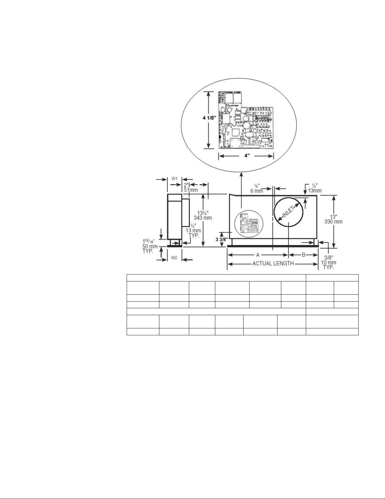
ONE AND TWO SLOT W2
NOMINAL
LENGTH ACTUAL
LENGTH INLET A B W1 2SLOT
1WAY 2SLOT
2WAY
36” 35 ¾” 5 7/8” 21 1/16” 14 11/16” 4” 3 ¾” 4 “
48” 47 ¾” 7 7/8” 28 1/16” 19 11/16” 4” 3 ¾” 4”
FOUR SLOT W2
NOMINAL
LENGTH ACTUAL
LENGTH INLET A B W1 4SLOT1 WAY
48” 47 ¾” 9 7/8” 28 1/16” 19 11/16” 6 5/16” 6”

3
Create a LonMaker Network
1. To create a new network:
From Windows desktop click on Start -> Programs -> LonMaker For Windows.
From the first window screen of LonMaker click on the ‘New Network’ button then enter the new network
name in the ‘Network Name’ field. Accept the default values for the ‘Network Database Path’ and ‘Network
Drawing Path’ then click on ‘Next’ and go to step 4.
2. To open an existing network:
From Windows desktop click on Start -> Programs -> LonMaker For Windows.
From the drop down list in the ‘Drawing Directory’ field, choose the network you want to open, then click on
‘Open Network’.
3. In the ‘Network Interface’ window, select ‘Network Attached’ if the PC is attached to the physical network and
you want to communicate with the devices. Accept the default ‘Network Interface’ or choose the appropriate
network interface if you have more than one network interface in your PC. Click ‘Next’.
4. Enter your user name and password if required. Check the ‘Write Access’ box if you are going to make
changes to the network.
5. If you are connected to the network, the ‘Management Mode’ window will appear. Check the ‘OnNet’ option if
you want changes to be propagated immediately to the device. If the ‘Offnet’ option is checked, changes won’t
be propagated to the devices on the network until LonMaker is ‘OnNet’. Click ‘Next’.
6.
The ‘Plug-in Registration’ window allows you to choose which plug-ins to register with this network. Click
‘Finish’.
Introduce The EL To LonMaker Network
1. Place a ‘Device’ shape on the drawing by dragging it from the LonMaker basic shapes stencil.
2. The ‘New Device Wizard’ window appears. Provide a ‘Device Name’ and select ‘Commission Device’ if
LonMaker is in the ‘Online’ mode. Press ‘Next’.
Note: If EL devices are added to the network in ‘Offline’ mode or ‘Commission Device’ option is not selected, a
‘Configuration Properties Warning’ box is displayed with the following contents: ‘There are no default
configuration properties available for this device. If this device was previously installed in another system, its
configuration properties values may need to be reset’. Click OK.
3. The ‘Specify Device Template’ window appears. If the EL being added is the first, check the ‘Load XIF’ option
and then select ‘Browse.’
Note: The XIF file provides LonMaker For Windows information about the EL.
4. Navigate to the directory where the EL.XIF file is located then double click on it. You will be returned to the
‘Select Device Template’ window with the ‘File’ and ‘Template Name’ fields defined based on your selection.
Press ‘Next’ to continue.
Note: If the EL being added has been placed on the drawing before, its template will already be available and
can be accessed by checking the ‘Existing Template’ option. Then the ‘Name’ can be selected from the drop
down list provided.
5. The ‘Specify Device Channel’ window appears. Select ‘TP/FT-10’ as the ‘Xcvr Type’ and if necessary select
the appropriate channel from the ‘Name’ drop down list. Press ‘Next’ to continue.
6. The ‘Specify Device Properties’ window appears. Accept the default settings and press ‘Next’ to continue.
7. The ‘Identify Device’ window appears. You can choose either the ‘Service Pin’ or ‘Manual’ method of
identifying the controller. Typically, the default service pin method is selected. Press ‘Next’ to continue.
8. The ‘Specify Device Application Image Name’ window appears. Typically no changes are required to this
screen so press ‘Next’ to continue.
9. The window titled ‘New Device Wizard’ appears. This is when you define the state of the device and the source
of the configuration property values. Select ‘Online’ for the state and ‘Default values’’ for the source of the
configuration properties values. Press ‘Next’ to continue.
10.
A screen appears prompting for a service pin. (See sketch, p. 10) Press the service pin on the EL to finish the
commissioning process. In the project drawing, the device shape should now be green indicating it is
addressed and online.
Create LonMaker Functional Block
1. A functional block represents a collection of network variables and configuration properties that perform a
related function on a device. To create functional blocks for the EL:
2. Place a Functional Block shape on the drawing by dragging it from the LonMaker Basic Shapes stencil.
The ‘New Functional Block Wizard’ window appears. This is where the device and functional block instances
are selected. In the ‘Device’ area, set the ‘Name’ of the EL associated with this functional block. In the
‘Functional Block’ area, set the ‘Name’ of the functional block to ‘Virtual Functional Block’.

4
Configure The EL
The EL unit is shipped with the default values shown below. When configuring, review the default values and
change only what is necessary
:
Configuration Variables
Function Description
Symbol On Screen
(SCPTs, SNVTs)
Default value Range Available
Occupancy
Temperature
Setpoint
The temperature setpoint of
the space to be maintained
by the EL for the
occupancy modes:
occupied, unoccupied,
standby.
SCPTsetPnts
1
23°C (73.4°F),
25°C (77°F),
27°C (80.6°F),
21°C (69.8°F),
19°C (66.2°F),
16°C (60.8°F)
50 – 95F (10 –35C)
1
This variable consists of six fields: Occupied cool, standby cool, unoccupied cool, occupied heat, standby heat,
unoccupied heat
Function Description
Symbol On Screen
(SCPTs, SNVTs)
Default value Range Available
Location
Label
This is designation for the
space in which the EL is
located, i.e. Conf Rm 12 SCPTlocation Blank Max length: 31 characters
Maximum
Flow Reserved for future use. SCPTmaxFlow 65535 l/s Do not change from
factory default setting.
Occupancy
Bypass Time
The amount of time in
seconds the EL operates in
occupied mode when the
occupancy input is set to
OC_BYPASS.
nciOccBypassTime 30 6553.4 secs.
Operation
Mode
Configures the EL to operate
in cooling only or heat and
cool mode. nciHeatCoolMode HVAC_AUTO
HVAC_AUTO,
HVAC_HEAT,
HVAC_COOL,
HVAC_MRNG_WRMUP,
HVAC_NIGHT_PURGE
Receive
Heartbeat
The maximum time that
elapses after the last update
to a bound network input
before the VAV object adopts
a default value for the
following: nviSpaceTemp,
nviSetpointOffset,
nviApplicMode,
nviEnergyHoldOff, nviCO2,
nviDuctTempIn
SCPTmaxRcvTime 0 0 sec – 6553.4 sec
Send
Heartbeat
The maximum period of time
that expires before the
following network variable
outputs will automatically be
updated: nvoSpaceTemp,
nvoUnitStatus, nvoBoxFlow,
nvoTerminalLoad,
nvoEffectSetPt,
nvoEnergyHoldff
SCPTmaxSendTime 0 0 sec – 6553.4 sec
Minimum
Send Time
The minimum period of time
between output network
variable transitions. SCPTminSendTime 0 0 sec – 6553.4 sec

5
Minimum
Flow Reserved for future use. SCPTminFlow 0 Do not change from
factory default setting.
Minimum
Flow
Standby Reserved for future use. SCPTminFlowStby 0 Do not change from
factory default setting.
Duct Area Reserved for future use. SCPTductArea 0 Do not change from
factory default setting.
CO2 Set
point Reserved for future use. nciCO2Threshold 5000 Do not change from
factory default setting.
Input Network Variables
Function Description
Symbol On Screen
(SCPTs, SNVTs)
Default value Range Available
Space
Temperature
Allows the EL to connect to a
space temperature sensor
other than the one installed in
the EL.
nviSpaceTemp 327.67°C
(621.806°F) 0 –327.67°C
(0 – 621.806°F)
Temperature
Setpoint
Allows the temperature
setpoint for the occupied and
standby modes to be changed
via the network. It is used to
reset the temperature rather
than change them.
nviSetPoint 327.67°C
(621.806°F) 10 – 35°C
(50 – 95°F)
Setpoint
Offset
Shifts the temperature control
point via the network. It is
typically bound to a
supervisory node providing
outside air temperature
compensation or to an
external wall diffuser having a
relevant setpoint knob.
Operates only on occupied
and standby setpoints.
nviSetPtOffset No offset =
32°F/0°C
-10°C to 10°C
(14°F to 50°F)
Occupancy
Commands the EL diffuser
into different occupancy
modes. It is typically set by a
supervisory node.
nviOccCmd OC_NUL
OC_OCCUPIED,
OC_UNOCCUPIED,
OC_BYPASS,
OC_STANDBY,
OC_NUL
Duct Inlet
Temperature
Allows the EL to be used with
another mfgr’s inlet
temperature sensor nviDuctInTemp 327.67°C
(621.806°F) 10 – 49°C
(50 – 120°F)
VAV Manual
Override Commands the controller into
a manual mode nviManOverride
HVO_OFF, 0.000, 0
2
See below
Emergency
Command
Commands the EL into
different emergency modes.
It is typically set up by a
supervisory node.
nviEmergCmd
EMERG_NORMAL
EMERG_NORMAL,
EMERG_PRESSURIZE,
EMERG_DEPRESSURIZE,
EMERG_PURGE,
EMERG_SHUTDOWN,
EMERG_NUL
Flow
Allows the EL to be used with
another manufacturers flow
sensor located on the
network.
nviBoxFlow 65535 l/s
(138862 cfm) 0 – 65535 l/s
(0 – 138862 cfm)

6
Energy
Hold-Off
Forces the EL into a lower
energy consumption mode.
For example, an opened
window could close the
diffuser in the cooling mode or
cause the EL to go to the
unoccupied setpoint if in the
heating mode
nviEnergyHoldOff 0.0 0 ( 2 fields
separated by a
space) 0 to 100%, 0 or 1
Terminal
Command
Input
This input network variable is
to be used for the trouble
shooting purpose by
manufacturer.
nviTermCmdIn <blank> N/A
CO2 Reserved for future use. nviCO2 32767 Do not change from
factory default setting.
Application
Mode The EL uses
'nciHeatCoolMode' instead nviApplicMode HVAC_AUTO See nciHeatCoolMode
2
This variable consists of three fields: state, percent, and flow.
Valid range
State : HVO_OFF, HVO_POSITION, HVO_FLOW_VALUE, HVO_PERCENT, HVO_OPEN, HVO_CLOSE,
HVO_MAXIMUM, HVO_MINIMUM, HVO_NULL
Percent:
Reserved for future use. Do not change from factory default setting.
Flow:
Reserved for future use. Do not change from factory default setting.
Note: Input network variables have higher priority than configuration variables.
Example: the EL diffuser will use the value of nviSetPoint (if this value is valid/non-default) as set point instead of
nciSetPnts.
Output Network Variables
Function Description
Symbol On Screen
(SCPTs, SNVTs)
Default value Range Available
Space
Temperature Reports current space
temperature. nvoSpaceTemp Current room temp 10 – 49°C
(50 – 120°F)
Supply Air
Temp
Reports the supply air
temperature to the network. nvoSupplyAirTemp Current SA temp 10 – 49°C
(50 – 120°F)
Unit Status
Reports EL status.
Combines the operating
mode, capacity of heating
and cooling used and any
indication of alarms
present.
nvoUnitStatus HVAC_OFF, 0.000,
0.000, 0.000, 0.000,
0.000, 0
3
See below
Effective
Setpoint
Informs the network of the
effective setpoint when the
setpoint is changed. nvoEffectSetPt Current set point 50 – 95°F (10 – 35°C)
Flow Reports what the EL flow
rate is. nvoBoxFlow Current flow See Performance Guide
Current
Energy
Hold-Off
State
Reports the current energy
consumption state of the
EL.
See Energy Hold-Off
nvoEnergyHoldOff 0.0 0 ( 2 fields
separated by a
space) 0 to 100%, 0 or 1
Terminal
Load
Reports energy use as a
function of percentage of
maximum flow setting and
supply air temperature.
nvoTerminalLoad 0.000 -163.84 % TO 163.84 %

7
Terminal
Command
Output
Reports the condition
requested by the
nviTermCmdIn variable. nvoTermCmdOut blank N/A
3
This variable consists of seven fields: operating mode, heat_output, heat_output_secondary, cool_output,
econ_output, fan_output, in_alarm.
Valid range
Operating mode : HVAC_HEAT, HVAC_COOL, HVAC_MRNG_WRMUP,
HVAC_NIGHT_PURGE, HVAC_OFF.
Heat_output : 0 – 100 % Max Flow
Heat_output_secondary : Not used
Cool_output : 0 – 100 % Max Flow
Econ_output : Not used
Fan_output : Not used
In_alarm : Refer to Acutherm EL Trouble Shooting Guide
Power Failure
Configuration values are stored in non-volatile memory so that the EL diffusers can resume normal operation when
power is restored after failure. Input network variable values will be restored only if updated via network.
Binding Network Variables
1. Drag an ‘Input’ or ‘Output’ Network Variable shape from the LonMaker Basic Shapes stencil over to the drawing
and place it on top of the Functional Block.
2. The ‘Choose a Network Variable’ window appears. Choose one or more of the network variables available for
the specified functional block and click ‘OK.’ The network variables selected appear on the functional block.
3. Drag a Connector shape to the drawing and drop it so one end of the connector shape locks onto one of the
network variables you want to connect (the point where they connect will be highlighted red). Then drag the
unconnected end of the connector shape to the other network variable you want to connect.
4. Repeat steps 1, 2, 3 for other network connections.
Putting The EL In Operating Mode
1. If the network was built off-site and it is time to put the physical EL in operating mode, connect wires to the EL
and then from the network drawing right click on the particular EL device shape and choose ‘Commission’.
2. A screen appears prompting for a service pin. Press the service pin (sketch, p.10) on the EL to finish the
commissioning process. In the project drawing, the device shape should now be green indicating it is
addressed and online.
AIR DENSITY COMPENSATION
Installation at altitudes above 1650 ft/ 503 m requires modified settings for air density effects. This can be factory
or field installed as follows:
Use the network management tool to set the value of the network variable ‘nviTermCmdIn’ according to the table
below: Altitudes nviTermCmdIn
1648 – 3279 ft / 502 – 999 m “altoffset#1650”
3280 – 4920 ft / 1000 – 1500 m “altoffset#3500”
4921 – 6561 ft / 1500 – 2000 m “altoffset#5500”
6562 – 8202 ft / 2000 – 2500 m “altoffset#7000”
Above 8202 ft / 2500 m “altoffset#9000”
Example: To operate an EL diffuser at 2000 ft / 610 m, set nviTermCmdIn to “altoffset#1650” (no
space between characters).
SYSTEM AIR BALANCING
VAV systems are balanced for design air volume at maximum air flow and systems using Therma-Fuser VAV
diffusers are no exception. When all the Therma-Fuser diffusers are set for maximum airflow by fully opening them,
the system is really a constant air volume system and is balanced as a constant volume system. Balancing
dampers are best located at the takeoff before the runout to the diffuser.

8
1. Prepare system for balancing. (Make necessary checks for diversity, fan capacities, fan rotation, minimum
outside air requirements, duct leaks and static pressure controller design setting. Set outside air control
damper for minimum air and return air control damper for maximum air.)
2. Open EL diffusers for balancing.
EL diffusers are opened by using balancing stops (contact factory)
or
by adjusting the value of the network variable ‘nviManOverride’ to
‘HVO_OPEN, 0.000,0’. Allow 10-15 minutes for all diffusers to open
fully.
3. Start fans, adjust system for 100% air flow and make system checks.
(Measure static pressure across filters and coils and at sensor for static
pressure controller. Measure supply, return and branch duct air flow.)
4. Measure air flow from each EF diffuser and adjust the damper at the duct takeoff to obtain maximum design air
flow. Air flow measurement may be with a direct reading diffuser balancing hood or air velocity meter. In
either case, measurements are made with all appearance panels in place. This is because the
appearance panel affects pressure drop through the diffuser. When velocity meter is used to measure the
discharge velocity, the velocity is measured at the top edge of the housing.
5. When balancing is complete, return each model EF diffuser to normal operation by
removing the balancing stop
or
returning the value of the network variable ‘nviManOverride’ to ‘HVO_OFF, 0.000, 0’.
Note: Diffuser noise is caused by higher velocity air through the diffuser which is caused by a high static
pressure. Acutherm recommends a static pressure no higher than .25” wg/ 62 Pa but some system designers
may accept higher noise levels and opt for a higher static pressure. Care should be taken not to exceed the
design maximum static pressure at the takeoff to the first EF diffuser after the static pressure control or, if none,
after the fan.
TROUBLE SHOOTING
Before examining the Therma-Fuser diffuser for failure it is worth the time to be sure the system is functioning
properly and that nothing has been overlooked.
The system should be
:
1. Delivering 50º–68ºF/ 10º–20ºC supply air when in the cooling mode.
2. Delivering 80º–120ºF/ 26.5º–49ºC supply air when in the heating mode.
3. Maintaining static pressure at the inlet to each Therma-Fuser diffuser between .05 and .25”wg/ 12 Pa and 62
Pa.
4. Maintaining continuous fan operation during occupied hours.
Once the above checks have been completed examine and record the following:
1. Conditions outside the EL
A. Room temperature 4 ft/1200 mm above the floor directly under the Therma-Fuser diffuser.
B. Supply air temperature at the Therma-Fuser diffuser. (Temperature may vary over time. Several
measurements at different times may be required.)
C. Static pressure at the inlet of the Therma-Fuser diffuser.
2. EL General
A. Determine the current setpoint.
•Use a computer on the network with software for LonMaker or other network management tool to
select or highlight the specific EL unit.
•Browse the network variables to locate the variable “nvoEffectSetPt”. The value of this variable is the
current setpoint for the EL unit.
•Check that other network variables are not overriding the current setpoint or limiting flow.
Following are network variables that can override and the normal operation for each.
nviEmergCmd = “EMERG_NORMAL” or “EMERG_NUL.”

9
nviManOverride = “HVO_OFF,0.000,0.”
nviEnergyHoldOff = “0.00 0.”
If they are other than as shown above, temporarily set the variables for normal operating condition
before further checking the EL unit.
B. Damper blade position estimated visibly from views shown below:
C. Use the information from steps 1 and 2 on the previous page to determine if the damper blades are correct
for the conditions.
•Determine mode. The EL unit should be in cooling if the supply air temperature (1.B. previous page) is
below the set point (2.A. previous page). It is heating if the supply air temperature is above both the
room temperature and the set point.
•For room temperatures (1.A. previous page) more than 2ºF/1.2ºC from set point (2.A. previous page),
damper blades should be as shown in the table below.
Notes:
Room temperature more than ±2ºF/1.2ºC from set point has been selected as a general rule of thumb
for trouble shooting to avoid more complicated control algorithms within that band. Control is intended
to be tighter but will depend on system conditions.
If any of the set points are changed to achieve full open or full closed conditions, wait 5 to 10 minutes
to make sure the room and system have stabilized.
For room temperatures less than 2ºF/1.2ºC from setpoint, the damper blades may be somewhere
between open and closed.
MODE ROOM TEMP minus
SET POINT DAMPER BLADE
POSITION (sec 2.B.) VOLTAGE TO THE
HEATER (sec 2.E.)
+2 F/1.2 C Open > 25VDCCooling - 2 F/1.2 C Closed < 1VDC
+2 F/1.2 C Closed < 1VDCHeating - 2 F/1.2 C Open > 25VDC
D. If the damper blades are not according to the table, check for any overrides limiting opening or closing?
See step 2.A. on the previous page.
E. If there are no limiting flow
stops or overrides, measure
the voltage supplied to the
heater. Remove the controller
cover and measure the voltage
across the terminals marked
heat. See sketch of controller.
If the voltage is not according
to the above table, complete
step 3 “EL Electrical” before
contacting Acutherm.

10
3. EL Electrical
A. LED indicators on EL board.
•Yellow off / Green on – unit operating OK.
See D. Both LED’s off – no power. Supply
voltage should be 22-26 VAC. Measure
voltage between terminal screws.
•If not 22-26 VAC, check source and make
sure wire are making contact with the
terminals.
•Yellow on / Green off – no program.
Contact Acutherm.
•Yellow blinking / Green off – needs to be
commissioned using network
management tools.
•Yellow off / Green blinking (long: 1 sec, short: .5 sec)
1 long 1 short = Faulty room temp. sensor / wiring connection. See C. below.
1 long 2 short = Faulty supply air temp. sensor / wiring connection. See C. below.
1 long 3 short = Out-of-range reference voltage. Must be cleared by resetting. See D.
1 long 4 short = Faulty flow sensor / wiring connection. See C. below.
•Both LED’s on – contact Acutherm.
B. Network Information
•Use a computer on the network with software for LonMaker or other network management tool to select
or highlight the specific EL unit.
•Browse the network variables to locate “nvoUnitStatus.”
•Go to the end of the fields and look at the last number set which is “ALARM”. The alarm codes are:
1= Faulty room temp. sensor / wiring connection. See C. below.
2= Faulty supply air temp. sensor / wiring connection. See C. below.
4= Faulty flow sensors / wiring connection. See C. below.
8= Out-of-range reference voltage. Must be cleared by resetting. See D.
Combinations of codes are:
3=1+2 7=1+2+4 11=1+2+8 15=1+2+4+8
5=1+4 9=1+8 12=4+8
6=2+4 10=2+8 13=1+4+8
C. Where faulty sensor / wiring connections are indicated, remove the controller cover. Then remove the
wires to each sensor (room temp, duct temp and flow 1) from the terminal and measure the resistance
between each wire and the terminal marked common. If the resistance is between 360 and 2000, reinstall
the wire making sure that it makes contact with the terminal. If the resistance is outside the range, check
the common terminal connections. If all common wires are in contact with the terminals and the resistance
is still outside the range, contact Acutherm.

11
D. Resetting may clear a communication problem and is necessary for an out-of-range reference voltage
fault. Methods for resetting are:
•Power off and then on. This can be done by removing one of the 24 volt power wires from the terminal
and then reconnecting it. Be careful not to touch anything else with the bare wire as it’s live.
•Send a reset command from a computer on the network with software for LonMaker or other network
management tool. An error message means resetting was unsuccessful. If so, try resetting by power
off and then on. Wait 2 to 3 minutes after resetting before rechecking the condition of the EL unit. If it
still has a communication problem or signals an out-of-range reference voltage, contact Acutherm.
MAINTENANCE
The moving parts of the EL diffuser have no maintenance or lubrication requirements. We are often asked to
recommend periodic maintenance procedures and a spare parts stock. Recommended maintenance is to clean the
outer surfaces of the Therma-Fuser diffuser—nothing else. We do not recommend stocking any spare parts. Our
customers also confirm that stocking is unnecessary.
CONTROLLING THE SYSTEM
References:
•System Design, p4.
•Chapters 2.2, 3.1 and 3.2, pp 6, 7 and 8, Designing Modular VAV Systems, Form 5.2
•Air Handling and Fan Coil Units Subzoned with Therma-Fuser VAV Modules, Form 6.7
•DX Equipment Zoned with Therma-Fuser VAV Modules, Form 6.5
Supply Air Temperature
The sources of cooling and heating are controlled from supply air temperature. As with all VAV systems the goals
are to achieve a constant supply air temperature (may be reset to another constant supply air temperature) and to
limit the supply air temperature. Limits for supply air temperature should be between 50°F/10°C and 68°F/20°C
when cooling and between 80°F/26.5°C and 120°F/49°C when heating. The heating temperature limit should be as
low as possible. These objectives are best achieved by modulating chilled water valves, hot water valves and other
variable equipment from supply air temperature. On/off equipment such as DX compressors and electric heat are
cycled from supply air temperature. Use a discharge air sensor for the supply air temperature signal.
Mode change between heating, recirculation and cooling is controlled from room temperature. Signals from the EL
Therma-Fuser may be used for mode change. A “majority rules” approach is recommended.
See the flow charts on the next page for an example control sequence.
Static Pressure
As with all VAV systems, the fan must run continuously during occupied times. Goals of static pressure control are
to provide enough static pressure to obtain the required air volume especially at the diffuser farthest from the fan, to
limit static pressure at both full flow and turndown to avoid diffuser noise and to provide pressure independence or
consistent operation as the system flow changes.
These objectives can be achieved with the usual methods of automatic static pressure control: bypass dampers,
discharge dampers, zone dampers, and fan control (variable speed drives, inlet dampers, etc.). Locate the static
pressure sensor as far down the duct as possible—at least 2/3 down the duct from the first takeoff.

12
START
RESET/
POWERED UP
?
COOL OFF
HEAT OFF
FAN OFF
HAS IT BEEN
10 SECS?
N
Y
OCCUPIED
MODE ?
YTIME FOR
WARM UP?
SEE WARM UP
FLOW CHART
MORE THAN HALF ROOM TEMPS
< UNOCCUPIED SETPTS
FAN ON
HEAT ONY
FAN OFF
HEAT OFF
N
N
SEE OCCUPIED
FLOW CHART
N
TURN THE FAN
ON
Y
FROM
OTHER
FLOW
CHARTS
Flow Chart For AHU Controller
(Main Page)
WARM UP IS OPTIONAL
OTHERWISE GO TO
OCCUPIED
WE SUGGEST A 10
SEC CONTROLLER
CYCLE BECAUSE IT
MATCHES THE 10 SEC
EF CYCLE
WARM UP
FLAG
CLEARED?
Y
N
Y
WARM UP
FLAG
CLEARED?
N
SET WARM UP
FLAG
Y
N

13
Flow Chart For AHU Controller
(Occupied Mode)
START
IS SYSTEM IN
COOLING?
MORE THAN HALF
ROOM TEMPS <
SETPT?
IS 30 MIN.
TIMER SET?
N
COOLING OFF
SET THE 30 MIN.TIMER
SET THE 30 SEC. TIMER
Y
N
PUT SYSTEM IN
HEATING MODE
HAS 30 SEC
TIMER
EXPIRED?
Y
MORE THAN
HALF ROOM
TEMPS >
SETPT?
Y
HAS IT BEEN
30 MINS.?
N
Y
PUT SYSTEM IN
COOLING MODEYY
RESET THE 30
SEC TIMER
N
CLEAR ALL
TIMERS
TO MAIN
FLOW
CHART
N
COOL ON
IS 30 MIN.
TIMER SET?
MORE THAN
HALF ROOM
TEMPS >
SETPT
N
N
HEAT ON
HEAT OFF
SET THE 30 MIN. TIMER
SET THE 30 SEC. TIMER
Y
HAS THE 30
SEC TIMER
EXPIRED?
Y
MORE THAN
HALF ROOM
TEMPS <
SETPT?
PUT SYSTEM IN
HEATING MODE
Y Y
HAS THE 30
MIN. TIMER
EXPIRED?
N
PUT SYSTEM IN
COOLING MODE
Y
RESET THE 30
SEC TIMER
N
CLEAR ALL
TIMERS
N
N
WE RECOMMEND A 30
MIN. TIME DELAY
BETWEEN MODES
(COOLING & HEATING)
REVIEW ROOM SET PTS
EVERY 30 SECS WHEN IN
RECIRCULATION

14
START OF
MORNING
WARM UP
IS MONITOR
FLAG SET?
SYSTEM
MODE=COOL
30 SEC TIMER
EXPIRED?
Y Y
MORE THAN
HALF ROOM
TEMPS <
SETPTS?
SYSTEM MODE =
HEAT
Y
30 MIN TIMER
EXPIRED ?
N
Y
MORE THAN
HALF ROOM
TEMPS >
SETPTS?
N
HEAT OFF
SET MONITOR
FLAG
SET 30 MIN.
TIMER
Y
HEAT ON
RESET THE 30
SEC TIMER
N
NCLEAR WARM
UP FLAG
CLEAR ALL
TIMERS
TO MAIN
FLOWCHART
Flow Chart For AHU Controller
(Warm Up)
HAS IT BEEN 30
MINS.SINCE WARM
UP?
N
Y
N
SET THE 30 SEC.
TIMER
REVIEW ROOM SET PTS
EVERY 30 SECS

15
MEASURING ENERGY CONSUMPTION
Supply air temperature, room temperature and flow from the EL can be logged and used to calculate the energy
used by each diffuser in BTU/HR or watts. This function will have to be written into either a computer connected to
the network or another device capable of this type of computation. The formula’s are:
BTU/HR = difference in °F between supply and room temps X flow in cfm X 1.10
Watts = difference in °C between supply and room temps X flow in l/s X 1.23
TWO YEAR WARRANTY
Acutherm warrants that its EL Therma-Fuser diffusers, exclusive of any options and accessories (whether factory or
field installed) shall be free from defects in material or workmanship for a period of two (2) years from the date of
shipment and agrees to repair or replace, at its option, any parts that fail during said two (2) year period due to any
such defects which would not have occurred had reasonable care been taken, provided that such parts have been
inspected by Acutherm and found defective and provided the diffusers have been given normal and proper usage
and all parts and controls remain unaltered. Acutherm makes NO WARRANTY OF MERCHANTABLILITY OF
PRODUCTS OR OF THEIR FITNESS FOR ANY PURPOSE OR ANY OTHER EXPRESS OR IMPLIED
WARRANTY WHICH EXTENDS BEYOND THE LIMITED WARRANTY ABOVE. ACUTHERM’S LIABILITY FOR
ANY AND ALL LOSSES AND DAMAGES RESULTING FROM DEFECTS SHALL IN NO EVENT EXCEED THE
COST OF REPAIR OR REPLACEMENT OF PARTS FOUND DEFECTIVE UPON EXAMINATION BY
ACUTHERM. IN NO EVENT SHALL ACUTHERM BE LIABLE FOR INCIDENTAL, INDIRECT OR
CONSEQUENTIAL DAMAGES OR DAMAGES FOR INJURY TO PERSONS OR PROPERTY. Acutherm shall not
be responsible for freight to or from its plant in connection with the inspection, repair or replacement of parts under
the terms of this limited warranty nor for cost of removal or installation.
Subject to change without notice.
FORM 54.2 REV 0703 •
••
•Supersedes FORM 54.2 REV 0608
Table of contents
Popular Air Conditioner Accessories manuals by other brands

Tecnosystemi
Tecnosystemi Apply.co AirPur3 Plus 160 user manual

Midea
Midea Wi-Fi CMI user manual

HMS Networks
HMS Networks Intesis AC Cloud Control Configuration guide

Inovance
Inovance CV800 Series user manual

mundoclima
mundoclima OSK102 user manual

National Comfort Products
National Comfort Products NCHP-018-1019 installation guide