7
4. Install new control panel label over the old control panel
label to cover holes left by removal of old controls and
refer guests to the wall-mounted thermostat. See Fig. 16.
Wiring of Thermostat
1. Refer to installation instructions included with thermostat
for thermostat installation.
2. Route thermostat wires through grommet in remote wir-
ing access cover (supplied with kit).
3. Make thermostat wiring connection (6 wires) to remov-
able terminal block on control board, accessible through
the opening for thermostat wiring interface.
a. R to R (24 VAC)
b. C to C (common — must be connected for digital
thermostats)
c. Y to Y (compressor)
d. O to O (reversing valve)
e. G to G (Fan)
f. W to W (electric heater)
4. Plug thermostat wiring terminal block back on to control
board.
5. Attach remote wiring access cover to control box cover
using 2 screws provided (where knockout was removed
for thermostat wiring interface). See Fig. 18.
Installation Completion
1. Replace front panel.
2. Restore power to unit.
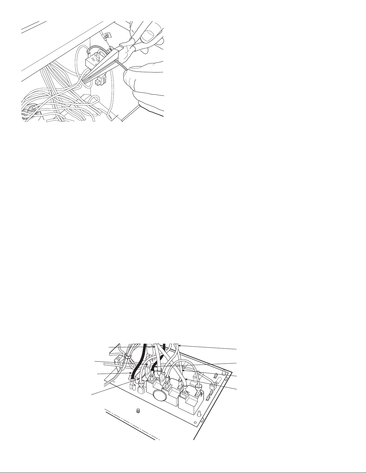
COOLING ONLY UNITS
Remove Existing Controls
1. Remove ALL 3 wires (yellow, white and orange) from
the fan cycle switch. See Fig. 6.
2. Remove the following wires from the push button switch:
a. Power cord wire from L1.
b. Black fan motor wire from HI.
c. Red fan motor wire from LO.
3. Remove Yellow compressor wire from thermostat,
terminal 1.
4. Remove the thermostat and push button switch controls
and all remaining attached wires and discard. Remove
thermostat bulb and mounting bracket from front of coil
and discard with the thermostat control. See Fig. 7.
Install New Wall Thermostat Controls
1. Remove knockout on control box cover for thermostat
wiring interface. See Fig. 8.
2. Mount wall thermostat control panel to front control box
cover using 3 of the no. 10 hex head screws provided. See
Fig. 9-11.
NOTE: Be sure removable terminal block on control
board is lined up with hole in control box cover from
knockout in previous step.
3. Re-connect wiring to fan/cycle switch. See Fig. 6.
a. Black Hi Fan speed wire to top terminal on fan/
cycle switch.
b. Red Low Fan speed wire to bottom terminal on
fan/cycle switch.
c. Grey Fan wire (factory installed on printed circuit
board from Relay K3, see Fig. 12) to center termi-
nal on fan/cycle switch.
4. Connect one end of Pink wire (included in plastic bag
labeled “For cooling only installations”) to the C terminal
on the capacitor. Connect the other end to L2 on relay
K2A1.
5. Re-connect the following wires on control board. See
Fig. 12.
a. Yellow compressor wire to COMP on relay Kl.
b. Power Cord wire (Ll) to L1 (brass post terminal)
on relay K2.
6. Secure control board ground wire (green) to ground
screw on control box door with power cord and chassis
ground wires. See Fig. 13.
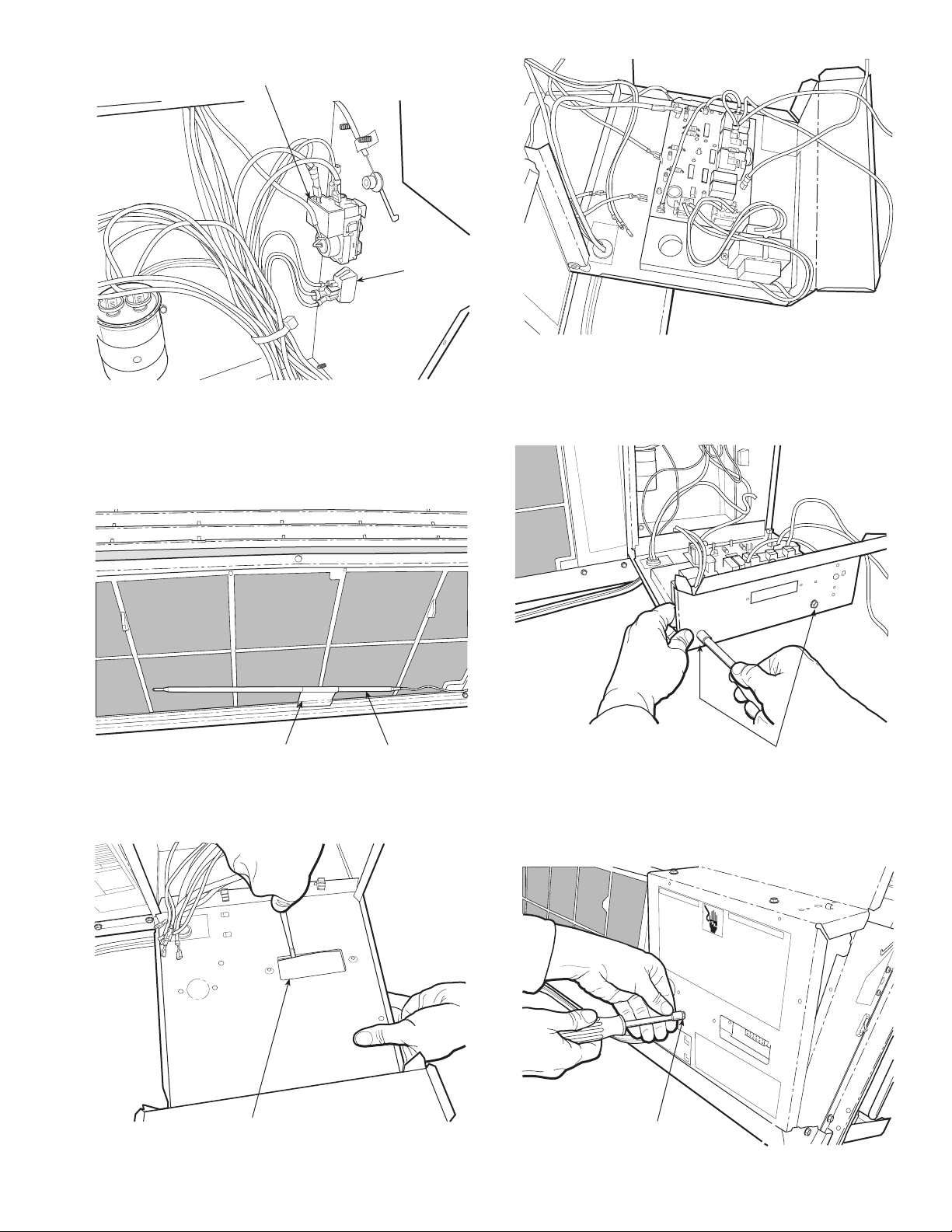
7. Remove coil filter. Install Indoor Coil Freeze Thermostat
(IFT) into coil.
a. Use a pen to make an opening in the fins 4-in. from
the right side of the coil between the second and third
tube from the top to install freeze sensor (Fig. 14).
b. Push freeze sensor into opening made in Step 7a.
c. Bend clip on scored line and install in fins (the curved
notches will lock clip in place) next to sensor to hold
sensor in place in the coil. See Fig. 15.
8. Replace filter (indoor coil freeze thermostat will be locat-
ed in the coil behind the filter).
9. Dress wires using wire ties provided.
10. Close the control box door and secure by re-attaching
screws saved earlier. See Fig. 3.
11. Reinstall plastic control panel cover using the 2 screws
removed earlier. See Fig. 3.
Install Labels and Schematics
1. Remove old wiring schematic label and install new wir-
ing schematic label in same location. See Fig. 16.
2. Install conversion label to front of control box. See
Fig. 16.
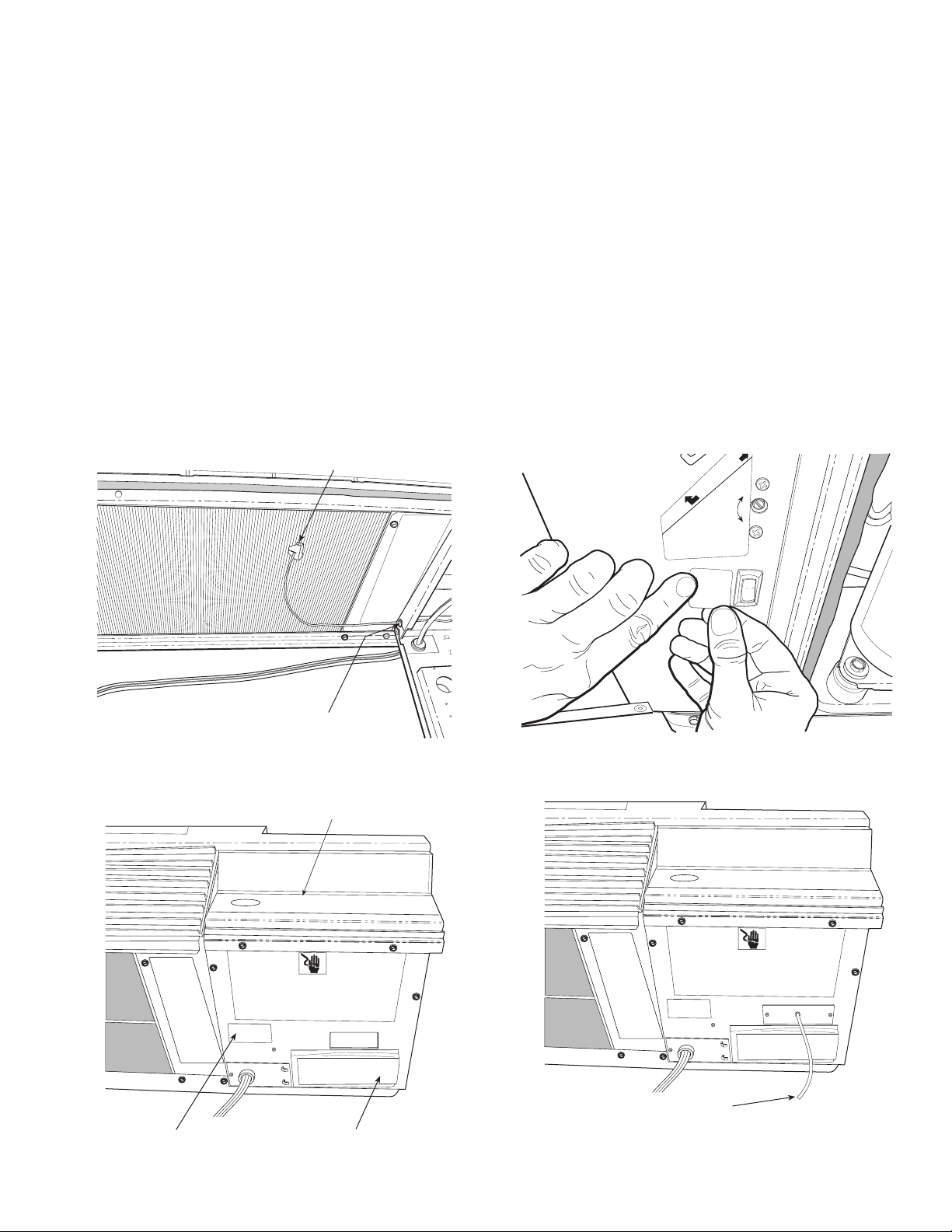
3. Install Hi Speed/Low Speed label next to fan cycle switch
on side of control box. See Fig. 17.
NOTE: Fan cycle switch now becomes a speed selec-
tor switch and selects whether the fan runs in high
speed or low speed. It is recommended to set the
switch to low fan speed for maximum sound comfort.
4. Install new control panel label over the old control panel
label to cover holes left by removal of old controls and
refer guests to the wall-mounted thermostat. See Fig. 16.
Wiring of Thermostat
1. Refer to installation instructions included with thermostat
for thermostat installation.
2. Route thermostat wires through grommet in remote wir-
ing access cover (supplied with kit).
3. Make thermostat wiring connection (4 wires) to remov-
able terminal block on control board, accessible through
the opening for thermostat wiring interface.
a. R to R (24 VAC)
b. C to C (common — must be connected for digital
thermostats)
c. Y to Y (compressor)
d. G to G (Fan)
4. Plug thermostat wiring terminal block back on to control
board.
5. Attach remote wiring access cover to control box cover
using 2 screws provided (where knockout was removed
for thermostat wiring interface). See Fig. 18.
Installation Completion
1. Replace front panel.
2. Restore power to unit.