manuals.online logo
Brands
  1. Home
  2. •
  3. Brands
  4. •
  5. Carrier
  6. •
  7. Air Conditioner Accessories
  8. •
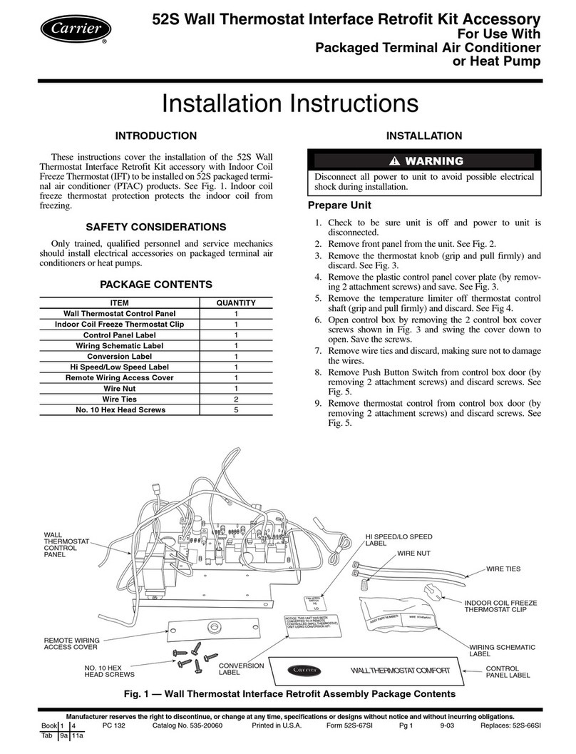
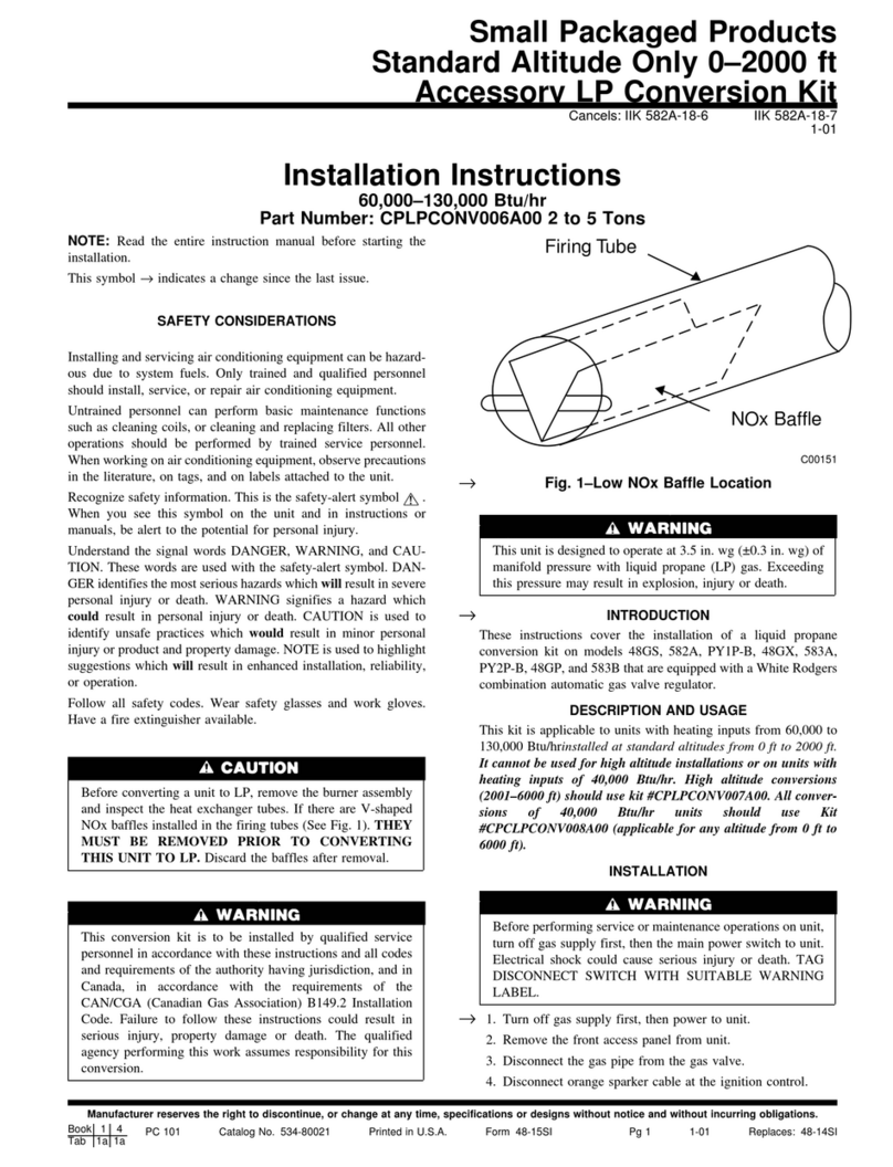
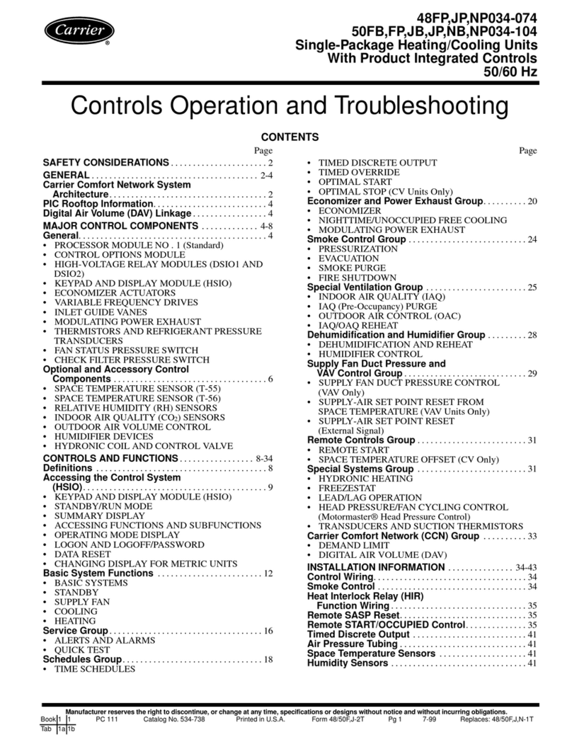
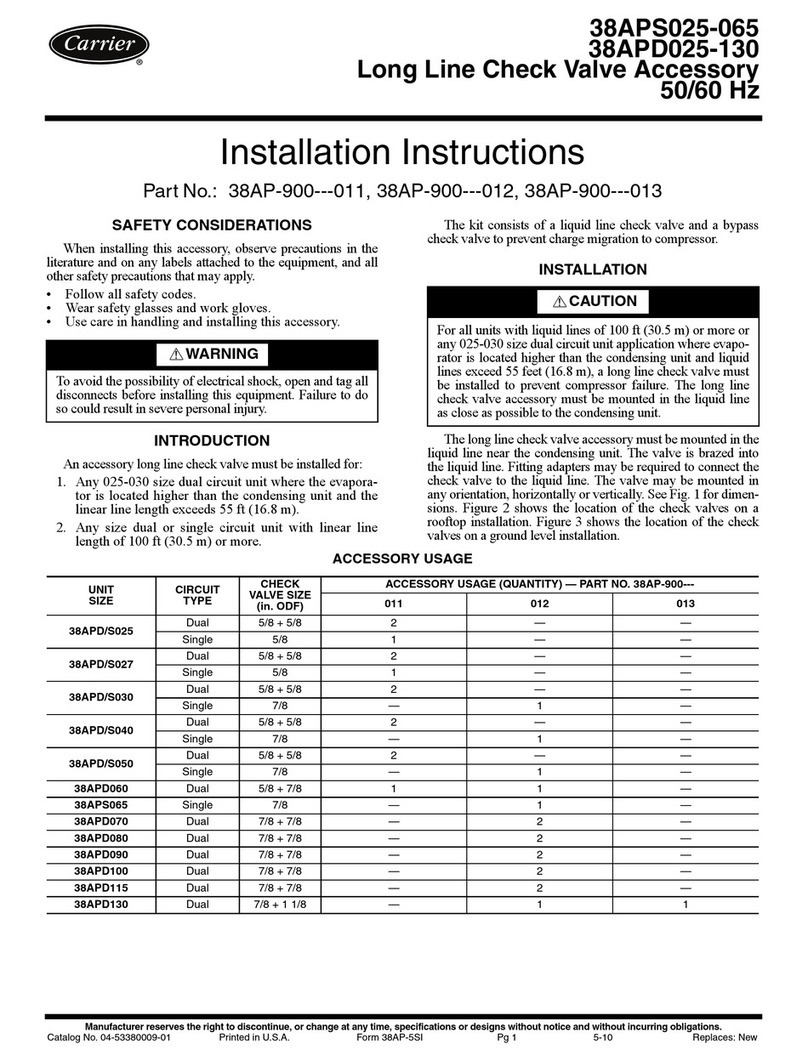
  9. Carrier 30HWA Series User manual

Carrier 30HWA Series User manual

Installation Instructions
Part No. 30HW900007
SAFETY CONSIDERATIONS
Installing, starting up, and servicing air-conditioning equip-
ment can be hazardous due to system pressures, electrical
components, and equipment location.
Only trained, qualified installers and service technicians
should install, start up, and service this equipment.
When working on air-conditioning equipment, observe pre-
cautions in the literature and on tags, stickers, and labels at-
tached to the equipment.
ELECTRICAL SHOCK HAZARD
To avoid the possibility of electrical shock,
open all disconnects before installing or
servicing this equipment.
GENERAL
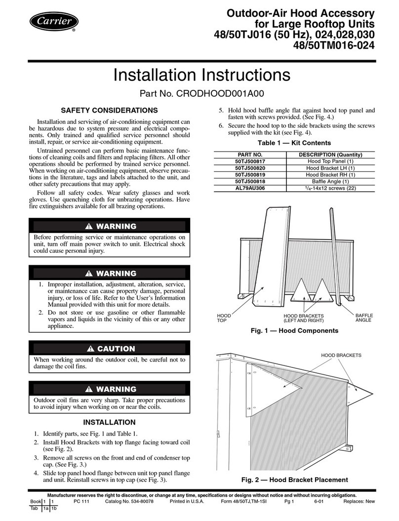
The accessory sound enclosure package consists of a set
of insulated sheet metal panels for mounting on 30HW units,
in order to achieve additional sound reduction where needed.
After all panels are mounted, the compressor compartment
will be completely enclosed with sound insulation panels.
CheckPackageContents— Check package for miss-
ing parts or shipping damage. If damage is found, or any
part is missing, file a claim with the shipper immediately.
See Table 1.
Table 1 — Accessory Package Contents
ITEM DESCRIPTION PART NO. QTY
1Insulated Basepan
Assembly (perforated) 30HW400027 4
2Support Angle 30HW500020 4
3Insulated Side
Panel Assembly
35
7
⁄
8
x26
3
⁄
4
in.
(911 x 679 mm) 30HW400023 2
4Insulated Front/Rear
Panel Assembly
30x26
3
⁄
4
in.
(762 x 679 mm) 30HW400025 2
5Self-Tapping Screws
1
⁄
4
-20 x
3
⁄
4
in. long AK92AB168 40
NOTE: Insulated basepans (Item 1) are constructed of 16-gage per-
forated steel plate.
INSTALLATION
To avoid the possibility of personal injury, obtain as-
sistance when installing this equipment. A minimum of
2 persons is required.
Step 1 — Read Instructions Carefully before pro-
ceeding with installation. See Fig. 1 and 2 for proper ori-
entation of assembled parts.
30HWA, HWB018-040
Accessory Sound Enclosure
50/60 Hz
Manufacturer reserves the right to discontinue, or change at any time, specifications or designs without notice and without incurring obligations.
Book 2
Tab 5c PC 903 Catalog No. 563-003 Printed in U.S.A. Form 30HW-2SI Pg 1 9-93 Replaces: New
Step 2 — Check Unit Disconnect Switch Amps
—If unit is equipped with factory-installed 100- or 200-
amp non-fused disconnect switch, you must remove the dis-
connect switch before installing the accessory sound
enclosure.
To remove the switch, first disconnect the electrical con-
duit and wiring to the disconnect switch, then remove the 2
upper and 2 lower screws that support the switch. The dis-
connect is to be replaced after sound enclosure kit installa-
tion is completed; save removed screws. It is not necessary
to remove 30- and 60-amp non-fused disconnects (if equipped).
Step 3 — Modify 2 Insulated Basepan Assem-
blies For Upper Section — Cut away part of 2 in-
sulated basepan assemblies (Item 1). See Fig. 3. These cut-
away areas permit the insulated basepan assembly to fit around
the control box conduit on one side, and around the suction
and discharge tubes on the other side. The remaining 2 in-
sulated basepan assemblies for the unit lower section do not
require any modification.
UNIT UPPER BASEPAN
WITH PRE-DRILLED
SCREW HOLES
CUT-AWAY
INSULATION
(SLOT 1) PRE-DRILLED
SCREW HOLES
UPPER SUPPORT
ANGLE (ONE EA SIDE)
CUT-AWAY
INSULATION
(SLOTS 2 AND 3)
MODIFIED UPPER
SECTION INSULATED
BASEPANS (2)
SUCTION LINE
DISCHARGE LINE
LIQUID IN
LIQUID OUT
LIQUID IN
123
123
Fig. 1 — Installing Insulated Basepan Assemblies in Unit Upper Section
UNMODIFIED LOWER
SECTION INSULATED
BASEPANS (2) LOWER SUPPORT
ANGLE (ONE EA SIDE)
PRE-DRILLED
SCREW HOLES
UNIT LOWER BASEPAN
WITH PRE-DRILLED
SCREW HOLES
Fig. 2 — Installing Insulated Basepan Assemblies in Unit Lower Section
Fig. 3 — Modifying Insulated Basepan Assemblies
for Upper Section
2
Step 4 — Cut Away Insulation Sections
a. On one of the modified insulated basepans (Item 1), cut
away the insulation from slot 1. See Fig. 3. This insulated
basepan will be installed under the control box. The con-
duit for the control box will pass through the slot which
has had insulation cut away (slot 1).
b. On the second modified insulated basepan, cut away the
insulation from slots 2 and 3. See Fig. 3. This insulated
basepan will be installed under the heat exchanger. The
suction and discharge lines will pass through the slots which
have had insulation cut away (slots 2 and 3).
Step 5 —Attach Support Angles (2) to Unit Up-
per Section
a. Obtain assistance (one or two persons) for holding the 2
modified insulated basepans (Item 1) in place beneath the
unit upper basepan while you mount 2 support angles
(Item 2). Install an angle on the unit basepan on each side
of the unit. See Fig. 4. Angles are installed underneath
the unit basepan behind the unit basepan sides.
b. Install four
1
⁄
4
-20 x
3
⁄
4
-in. long self-tapping screws
(Item 5) for each angle. See Fig. 4.
NOTE: The unit basepan has pre-drilled
5
⁄
16
-in. (8-mm)
diameter clearance screw holes. The support angles have
pre-drilled
3
⁄
16
-in. (5-mm) diameter engagement screw holes.
Step6—Attach SupportAngles(2) to Unit Lower
Section — Follow the same procedure as in Step 5, using
the 2 unmodified insulated basepans (Item 1), the remain-
ing 2 support angles (Item 2), and 8 of the
1
⁄
4
-20 x
3
⁄
4
-in.
long self-tapping screws (Item 5).
Step 7 — Install Insulated Side Panels to Unit
Bottom Section
IMPORTANT: If you removed the factory-installed 100-
or 200-amp non-fused disconnect switch (described in
Step 2), it must be mounted on the insulated side panel
(Item 3), using the pre-drilled mounting holes located
near the bottom-center of the panel. When mounting
the panel, be sure it is turned so that the mounting holes
are toward the bottom of the panel.
Remount the disconnect switch using the 4 screws
removed in Step 2, and reconnect wiring and electrical
conduit, making sure wire colors are properly matched.
Fasten the two 35
7
⁄
8
x26
3
⁄
4
-in. (911 x 679-mm) insulated
side panels (Item 3) to unit corner posts on each side of unit.
See Fig. 5. Use 6 of the
1
⁄
4
-20 x
3
⁄
4
-in. long self-tapping screws
(Item 5) for each panel. The panels have pre-drilled
5
⁄
16
-in.
(8-mm) diameter clearance holes. The unit corner posts have
pre-drilled
3
⁄
16
-in. (5-mm) diameter engagement screw holes.
Step 8 — Install Front/Rear Insulated Panels (2)
to Unit Bottom Section — Fasten the two 30 x 26
3
⁄
4
-
in. (762 x 679-mm) insulated front and rear panels (Item 4)
to the insulated side panels (Item 3) installed in Step 7. In-
stall one on the front, and one on the rear of the unit. See
Fig. 6. Use 6 of the
1
⁄
4
-20 x
3
⁄
4
-in. long self-tapping screws
(Item 5) for each panel. The panels have
5
⁄
16
-in. (80-mm)
diameter clearance holes. The side panels have pre-drilled
3
⁄
16
-in. (5-mm) diameter engagement screw holes.
LIQUID IN
LIQUID OUT
LIQUID IN
2 MODIFIED
INSULATED
BASE PANELS
OBTAINASSISTANCE FOR HOLDING
INSULATED BASEPANS IN PLACE
WHILE FASTENING SUPPORTANGLE
SCREWS TO UNIT BASEPAN
SUPPORTANGLE
(1 EA SIDE)
ANGLE FASTENER
SCREWS (4 EA SIDE)
UNIT
BASEPAN
Fig. 4 — Mounting Support Angles on Unit Upper Section
3
LIQUID IN
CORNER
POSTS
FRONT
SIDE PANEL
SCREWS
(6 EA PANEL)
INSULATED
SIDE PANEL
(1 EA SIDE)
26 3/4 IN.
(679 mm)
35 7/8 IN.
(911 mm)
Fig. 5 — Installing Insulated Side Panels to Bottom Section
INSULATED
REAR PANEL
MOUNTED
INSULATED
SIDE PANEL
30 IN.
(762 mm)
26 3/4 IN.
(679 mm)
Fig. 6 — Installing Insulated Front/Rear Panels to Bottom Section
Copyright 1993 Carrier Corporation
Manufacturer reserves the right to discontinue, or change at any time, specifications or designs without notice and without incurring obligations.
Book 2
Tab 5c PC 903 Catalog No. 563-003 Printed in U.S.A. Form 30HW-2SI Pg 4 9-93 Replaces: New

This manual suits for next models

5

Other Carrier Air Conditioner Accessories manuals

Carrier OSK102/EU Operating instructions

Carrier

Carrier OSK102/EU Operating instructions

Carrier GEMINI SELECT 38APD025-130 User manual

Carrier

Carrier GEMINI SELECT 38APD025-130 User manual

Carrier 52S Wall Thermostat Interface Retrofit Kit User manual

Carrier

Carrier 52S Wall Thermostat Interface Retrofit Kit User manual

Carrier 30GX900006 User manual

Carrier

Carrier 30GX900006 User manual

Carrier WF-60A1 Operating instructions

Carrier

Carrier WF-60A1 Operating instructions

Carrier KGACK0101HCK User manual

Carrier

Carrier KGACK0101HCK User manual

Carrier CPLPCONV006A00 User manual

Carrier

Carrier CPLPCONV006A00 User manual

Carrier 48FP Operating instructions

Carrier

Carrier 48FP Operating instructions

Carrier 52S series User manual

Carrier

Carrier 52S series User manual

Carrier CRECOMZR 004A01 Series User manual

Carrier

Carrier CRECOMZR 004A01 Series User manual

Carrier CRECOMZR001A02 Instructions and recipes

Carrier

Carrier CRECOMZR001A02 Instructions and recipes

Carrier 50TJ500817 User manual

Carrier

Carrier 50TJ500817 User manual

Carrier 324423-751 User manual

Carrier

Carrier 324423-751 User manual

Popular Air Conditioner Accessories manuals by other brands

Mitsubishi Electric PAC-645BH-E quick start guide

Mitsubishi Electric

Mitsubishi Electric PAC-645BH-E quick start guide

Hitachi E-102SN installation manual

Hitachi

Hitachi E-102SN installation manual

ActronAir CRQ2-14AS Installation and commissioning guide

ActronAir

ActronAir CRQ2-14AS Installation and commissioning guide

LG EEV Kit installation manual

LG

LG EEV Kit installation manual

Toshiba Carrier RBC-AX33UYP-UL Operation manual

Toshiba

Toshiba Carrier RBC-AX33UYP-UL Operation manual

Tecnosystemi smart clima Regio user manual

Tecnosystemi

Tecnosystemi smart clima Regio user manual

Daikin DP 14 Service instructions

Daikin

Daikin DP 14 Service instructions

Mitsubishi PAC-YG60 MCA-J Installation instructions manual

Mitsubishi

Mitsubishi PAC-YG60 MCA-J Installation instructions manual

ActronAir PKV160T Installation and commissioning guide

ActronAir

ActronAir PKV160T Installation and commissioning guide

Midea Wi-Fi CMI user manual

Midea

Midea Wi-Fi CMI user manual

Toshiba TCB-TDL0141SDY-E owner's manual

Toshiba

Toshiba TCB-TDL0141SDY-E owner's manual

SFA Sanicondens Clim deco quick start guide

SFA

SFA Sanicondens Clim deco quick start guide

Mitsubishi Electric PFR-12-18 How to Use / How to Install

Mitsubishi Electric

Mitsubishi Electric PFR-12-18 How to Use / How to Install

Tecnosystemi smart clima TSTT-140 A user manual

Tecnosystemi

Tecnosystemi smart clima TSTT-140 A user manual

Friedrich VRPXWPC-8 Installation & operation manual

Friedrich

Friedrich VRPXWPC-8 Installation & operation manual

manuals.online logo
manuals.online logoBrands
  • About & Mission
  • Contact us
  • Privacy Policy
  • Terms and Conditions

Copyright 2025 Manuals.Online. All Rights Reserved.