2
50ZPA
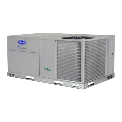
finish of the 50ZPA unit will keep it looking like
new for years. The paint treatment process
ensures quality protection against the elements.
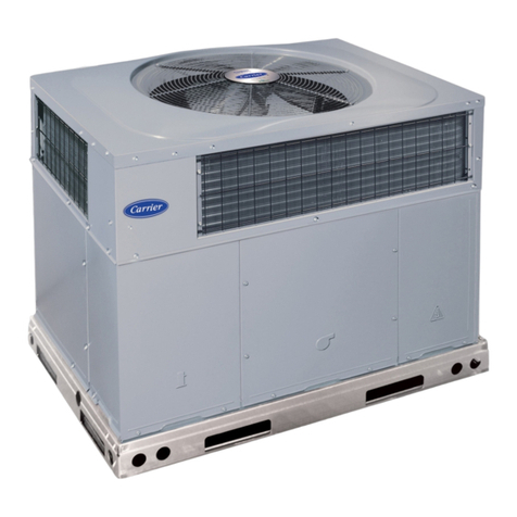
A compact, low-profile design utilizes a
louvered coil enclosure for protection against
vandalism and hail damage.
INDOOR AIR QUALITY
is designed into the
50ZPA units. A sloped drain pan minimizes the
amount of standing water inside the unit, which
limits mold and mildew growth. The drain pan
is made of a rust-proof material and will not
deteriorate or release foreign matter into the
airstream.
LIGHTWEIGHT, COMPACT
CONSTRUCTION
is ideal for manufactured
housing and residential applications. The
50ZPA unit is one of the lightest, most compact
packaged units ever designed. It’s light weight
(293 lbs for the 50ZPA024 unit) makes the unit
easier to handle. The low height keeps ductwork
connections to a minimum and makes units less
visible.
The 50ZPA units utilize a structural beam
design to form the four sides of the cabinet.
Only 12 different pieces of sheet metal are used
in the unit construction to simplify the unit for
greater reliability.
EFFICIENT, DEPENDABLE
PERFORMANCE
with durable compressors
designed for efficiency. The 50ZPA units offer
13.0 SEER (Seasonal Energy Efficiency Ratio)
cooling performance efficiencies. This
performance level can reduce cooling expenses
by as much as 25% compared to older cooling
equipment. A high-eficiency, multi-speed
blower motor system ensures quality
performance with most duct systems. The
computer-designed blower wheel is balanced
for quiet operation.
DURABLE, DEPENDABLE,
COMPRESSORS
are designed for high
efficiency. Each compressor is hermetically
sealed against contamination to help promote
longer life and dependable operation. Vibration
isolation provides quiet operation. Compressors
have internal high-pressure and overcurrent
protection.
DIRECT-DRIVE MULTISPEED, PSC
(PERMANENT SPLIT CAPACITOR)
BLOWER MOTOR
is standard on all models.
Direct-drive, PSC condenser-fan motors are
designed to help reduce energy consumption
and provide for cooling operation down to 40°F.
REFRIGERANT SYSTEM
is designed to
provide dependability. Liquid refrigerant
strainers are used to promote clean, unrestricted
operation. Each unit leaves the factory with a
full refrigerant charge. Refrigerant service
connections make checking operating pressures
easier.
ACCESSORY ELECTRIC HEATERS
— A
variety of accessory electric heaters are
available for the 50ZPA units. These heaters are
comprised of a separate heater module mounted
on the blower inlet and remote mounted controls
located in the unit control box. Single point
electrical connections are available for
powering both the heater and the unit.
Corporate Thermostat
— These provide
cooling control for unit. Autochangeover and
manual changeover types are available.
The MotorMaster II Low Ambient Kit
— Kit
permits operation down to 0° F. Use when
mechanical cooling is required when outdoor-
air temperature is between 40°F and 0°F.
Crankcase Heater
— Warms crankcase oil to
reduce refrigerant migration and ensure proper
compressor lubrication. For use in applications
where crankcase is subjected to low outside
temperatures. Recommended on 208/230-1-60,
size 024-042 units only.
Solid-State Time Guard
®
Device
— Package
consists of a control to be field-wired into the
unit controls, and provides a 5-minute delay in
compressor operation between cooling cycles.
Prevents compressor short cycling when rapid
compressor cycles may be a problem.
Controls Upgrade Kit
— Contains high- and
low-pressure switches to protect the unit from
running at unsuitable pressures. Provides
additional safety features when needed.
Outdoor Thermostat
— Accessory provides
control when outdoor-air temperature falls
below set point. Helps to bring second stage of
2-stage electric heater on line.
Table of contents
Page
Features/Benefits . . . . . . . . . . . . . . . . . . . . . . . . . . . . . . . . . . . . . . . . . . . . . . . . . . . . . . . . . . . . . . . . . . . . . . . . . . . . . . . . . . . . . . . . . . . . . . . . . . . . . . . . . . . 1
ARI Capacity Ratings. . . . . . . . . . . . . . . . . . . . . . . . . . . . . . . . . . . . . . . . . . . . . . . . . . . . . . . . . . . . . . . . . . . . . . . . . . . . . . . . . . . . . . . . . . . . . . . . . . . . . . . . 2
Model Nomenclature . . . . . . . . . . . . . . . . . . . . . . . . . . . . . . . . . . . . . . . . . . . . . . . . . . . . . . . . . . . . . . . . . . . . . . . . . . . . . . . . . . . . . . . . . . . . . . . . . . . . . . . . 3
Physical Data . . . . . . . . . . . . . . . . . . . . . . . . . . . . . . . . . . . . . . . . . . . . . . . . . . . . . . . . . . . . . . . . . . . . . . . . . . . . . . . . . . . . . . . . . . . . . . . . . . . . . . . . . . . . . . 3
Dimensional Drawings . . . . . . . . . . . . . . . . . . . . . . . . . . . . . . . . . . . . . . . . . . . . . . . . . . . . . . . . . . . . . . . . . . . . . . . . . . . . . . . . . . . . . . . . . . . . . . . . . . . . . 4-6
Selection Procedure . . . . . . . . . . . . . . . . . . . . . . . . . . . . . . . . . . . . . . . . . . . . . . . . . . . . . . . . . . . . . . . . . . . . . . . . . . . . . . . . . . . . . . . . . . . . . . . . . . . . . . . . . 7
Performance Data . . . . . . . . . . . . . . . . . . . . . . . . . . . . . . . . . . . . . . . . . . . . . . . . . . . . . . . . . . . . . . . . . . . . . . . . . . . . . . . . . . . . . . . . . . . . . . . . . . . . . . . . 8-11
Typical Wiring Schematics . . . . . . . . . . . . . . . . . . . . . . . . . . . . . . . . . . . . . . . . . . . . . . . . . . . . . . . . . . . . . . . . . . . . . . . . . . . . . . . . . . . . . . . . . . . . . . . 12-15
Electrical Data . . . . . . . . . . . . . . . . . . . . . . . . . . . . . . . . . . . . . . . . . . . . . . . . . . . . . . . . . . . . . . . . . . . . . . . . . . . . . . . . . . . . . . . . . . . . . . . . . . . . . . . . . . . . 16
Operating Sequence . . . . . . . . . . . . . . . . . . . . . . . . . . . . . . . . . . . . . . . . . . . . . . . . . . . . . . . . . . . . . . . . . . . . . . . . . . . . . . . . . . . . . . . . . . . . . . . . . . . . . . . . 17
Typical Installation. . . . . . . . . . . . . . . . . . . . . . . . . . . . . . . . . . . . . . . . . . . . . . . . . . . . . . . . . . . . . . . . . . . . . . . . . . . . . . . . . . . . . . . . . . . . . . . . . . . . . . . . . 17
Application Data. . . . . . . . . . . . . . . . . . . . . . . . . . . . . . . . . . . . . . . . . . . . . . . . . . . . . . . . . . . . . . . . . . . . . . . . . . . . . . . . . . . . . . . . . . . . . . . . . . . . . . . . . . . 18
Engineers’ Specification Guide . . . . . . . . . . . . . . . . . . . . . . . . . . . . . . . . . . . . . . . . . . . . . . . . . . . . . . . . . . . . . . . . . . . . . . . . . . . . . . . . . . . . . . . . . . . . . . . 19
ARI* capacity ratings
UNIT 50ZPA
(SERIES)
NOMINAL
TONS
STANDARD
CFM
NET COOLING CAPACITIES
AT 95°F (Btuh)† SEER**
SOUND
RATINGS†† (dB)
024 2.0 800 24,000 13.0 77
030 2.5 1000 29,000 13.0 81
036 3.0 1200 36,000 13.0 81
042 3.5 1400 40,000 13.0 81
048 4.0 1600 45,000 13.0 81
060 5.0 1900 52,000 13.0 83
LEGEND
db
— Dry Bulb
dB
— decibels
SEER
— Seasonal Energy Efficiency Ratio
wb
— Wet Bulb
* Air Conditioning & Refrigeration Institute.
† Rated in accordance with U.S. Government DOE Department of
Energy) test procedures and/or ARI Standard 210/240-89.
** All units have factory-installed time-delay relay.
†† Rated in accordance with ARI Standard 270-84.
NOTES:
1. Ratings are net values, reflecting the effects of circulating fan heat.
2. Cooling capacity ratings are based on cooling standard:
80°F db/67°F wb indoor air entering temperature
95°F db air entering outdoor unit
M
A
N
U
F
A
C
T
U
R
E
R
C
E
R
T
I
F
I
E
D
T
O
A
R
I
A
S
C
O
M
P
L
Y
I
N
G
W
I
T
H
A
R
I
S
T
A
N
D
A
R
D
2
1
0
U
N
I
T
A
R
Y
A
I
R
C
O
N
D
I
T
I
O
N
I
N
G
E
Q
U
I
P
M
E
N
T
REGISTERED
ISO 9001:2000

