manuals.online logo
Brands
  1. Home
  2. •
  3. Brands
  4. •
  5. Carrier
  6. •
  7. Air Conditioner
  8. •
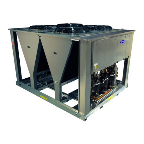
  9. Carrier 38BRC018 Manual

Carrier 38BRC018 Manual

This manual suits for next models

2

Other Carrier Air Conditioner manuals

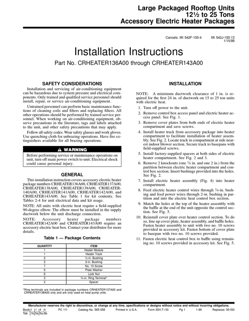
Carrier 42QTD012DS Series User manual

Carrier

Carrier 42QTD012DS Series User manual

Carrier 50PM20 User manual

Carrier

Carrier 50PM20 User manual

Carrier 38AK024-044 Dimensions and installation guide

Carrier

Carrier 38AK024-044 Dimensions and installation guide

Carrier 42GCVBE010-703 User manual

Carrier

Carrier 42GCVBE010-703 User manual

Carrier 40MKCF User manual

Carrier

Carrier 40MKCF User manual

Carrier RAS-09LKV-UL Series User manual

Carrier

Carrier RAS-09LKV-UL Series User manual

Carrier 38EC Dimensions and installation guide

Carrier

Carrier 38EC Dimensions and installation guide

Carrier XCT Series Installation instructions

Carrier

Carrier XCT Series Installation instructions

Carrier 53QPCT18H-708F User manual

Carrier

Carrier 53QPCT18H-708F User manual

Carrier bryant Preferred 577E Instruction Manual

Carrier

Carrier bryant Preferred 577E Instruction Manual

Carrier 48VG-A Instruction Manual

Carrier

Carrier 48VG-A Instruction Manual

Carrier 51FE User guide

Carrier

Carrier 51FE User guide

Carrier 24ACB7 Comfort Operation manual

Carrier

Carrier 24ACB7 Comfort Operation manual

Carrier 50SX Assembly Instructions

Carrier

Carrier 50SX Assembly Instructions

Carrier WeatherMaker 50FC-16 Series User manual

Carrier

Carrier WeatherMaker 50FC-16 Series User manual

Carrier W4A5S User manual

Carrier

Carrier W4A5S User manual

Carrier 50ZPB Instruction Manual

Carrier

Carrier 50ZPB Instruction Manual

Carrier 51 FA Series User manual

Carrier

Carrier 51 FA Series User manual

Carrier 38GS Dimensions and installation guide

Carrier

Carrier 38GS Dimensions and installation guide

Carrier 50K User manual

Carrier

Carrier 50K User manual

Carrier 42TVCA010 User manual

Carrier

Carrier 42TVCA010 User manual

Carrier KC_141P User manual

Carrier

Carrier KC_141P User manual

Carrier MMU-AP0072H2UL User manual

Carrier

Carrier MMU-AP0072H2UL User manual

Carrier 42KUE036N User manual

Carrier

Carrier 42KUE036N User manual

Popular Air Conditioner manuals by other brands

Fujitsu ASYG 09 LLCA installation manual

Fujitsu

Fujitsu ASYG 09 LLCA installation manual

York HVHC 07-12DS Installation & owner's manual

York

York HVHC 07-12DS Installation & owner's manual

intensity IDUFCI60KC-3 installation manual

intensity

intensity IDUFCI60KC-3 installation manual

Frigidaire FAC064K7A2 Factory parts catalog

Frigidaire

Frigidaire FAC064K7A2 Factory parts catalog

Sanyo KS2432 instruction manual

Sanyo

Sanyo KS2432 instruction manual

LG MultiV Series installation manual

LG

LG MultiV Series installation manual

CLIMAVENETA a-CHD U-2T 606+2209 OPERATING AND INSTALLATION Manual

CLIMAVENETA

CLIMAVENETA a-CHD U-2T 606+2209 OPERATING AND INSTALLATION Manual

Midea EWK06CW5 user manual

Midea

Midea EWK06CW5 user manual

Pioneer FAB Series installation manual

Pioneer

Pioneer FAB Series installation manual

SPT WA-1511S user manual

SPT

SPT WA-1511S user manual

Mitsubishi Electric Mr.Slim MSZ-A24NA operating instructions

Mitsubishi Electric

Mitsubishi Electric Mr.Slim MSZ-A24NA operating instructions

Mitsubishi Electric PUHZ-RP50VHA4 Service manual

Mitsubishi Electric

Mitsubishi Electric PUHZ-RP50VHA4 Service manual

Panasonic CS-S18HKQ Service manual

Panasonic

Panasonic CS-S18HKQ Service manual

Panasonic CS-E15NKE3 operating instructions

Panasonic

Panasonic CS-E15NKE3 operating instructions

Gree GWH18TC-K3DNA1B/I Service manual

Gree

Gree GWH18TC-K3DNA1B/I Service manual

Friedrich ZoneAire Compact P08SA owner's manual

Friedrich

Friedrich ZoneAire Compact P08SA owner's manual

Daikin R32 Split Series installation manual

Daikin

Daikin R32 Split Series installation manual

Daikin FFQ09Q2VJU Operation manual

Daikin

Daikin FFQ09Q2VJU Operation manual

manuals.online logo
manuals.online logoBrands
  • About & Mission
  • Contact us
  • Privacy Policy
  • Terms and Conditions

Copyright 2025 Manuals.Online. All Rights Reserved.

38BRC
018–060
60 Hertz
Wiring Diagrams
Fig. 1—38BRC018–048 208/230v, 1 Phase, 60 Hertz A03021
Visit www.carrier.com
Manufacturer reserves the right to discontinue, or change at any time, specifications or designs without notice and without incurring obligations.
Book 1 4
Tab 2a 3a PC 101 Catalog No. 533-80069 Printed in U.S.A. Form 38BRC-4W Pg 1 2-03 Replaces: 38BRC-3W
Fig. 2—38BRC060 208/230v, 1 Phase, 60 Hertz A98017
CH (NOTE #9)
RED or BLK BLK
208/230 1Ø
POWER
SUPPLY
L1
L2
EQUIP
GND
CONT
11 21
13 23 YEL
OFM
YEL
COMP BLU
BRN
BRN
YEL
S
C
RYEL
YEL
BLU BLU
BRN
*SC
BLK
BLK
*ST
*SR
12
5
CAP
*LPS
*DTS
*HPS BLK BLK YE
L
BLU
VIO
H
C
F
CONNECTION DIAGRAM
+t°
BLU
BLK
BLU YE
L*CTD
BRN
(NOTE #14)
BLU
BLU BLK *LLS BLK
Y RG
INDOOR THERMOSTAT (NOTE #5) INDOOR BLOWER MOTOR
EXTERNAL POWER
SUPPLY 24V
(NOTES #3 & #6)
(NOTE #8)
FACTORY POWER WIRING
FACTORY CONTROL WIRING
FIELD CONTROL WIRING
FIELD POWER WIRING
COMPONENT CONNECTION
FIELD SPLICE
JUNCTION
CONT CONTACTOR
CAP CAPACITOR (DUAL RUN)
*CH CRANKCASE HEATER
*CHS CRANKCASE HEATER SWITCH
COMP COMPRESSOR
*CTD COMPRESSOR TIME DELAY
*DTS DISCHARGE TEMP. SWITCH
*HPS HIGH PRESSURE SWITCH
IFR INDOOR FAN RELAY
*LLS LIQ. LINE SOLENOID VALVE
*LPS LOW PRESSURE SWITCH
OFM OUTDOOR FAN MOTOR
*SC START CAPACITOR
*SR START RELAY
*ST START THERMISTOR
* MAY BE FACTORY OR FIELD
INSTALLED.
-LEGEND-
SCHEMATIC DIAGRAM
(LADDER FORM)
11 21
CONT
L1
QUIP
GND *SR
*SC
52
1H
C
F
*ST
OFM
+t°CONT
23 13
CAP
S
CRCOMP
L2
*LPS
*DTS
*HPS CONT
IFR
EXTERNAL POWER SUPPLY 24 V
*CTD
(NOTE #14)
Y
G
R
OOR THERMOSTAT
RC
*CH
-NOTES-
1. Symbols are electrical representation only.
2. Compressor and fan motor furnished with inherent thermal
protection.
3. To be wired in accordance with National Electric N.E.C.
and local codes.
4. N.E.C. class 2, 24 Vcircuit, min. 40 VA required, 60VA on
units installed with LLS.
5. Use copper conductors only.
6. Connection for typical cooling onlythermostat, for other
arrangements, see installation instructions.
7. If indoor section has a transformer with a grounded
secondary, connect the grounded side to the BRN lead.
8. When start relay andstart capacitor areinstalled, start
thermistor is not used.
9. CH not used on all units.
10.If any of the original wire, as supplied, must be replaced,
use the same or equivalent wire.
11.Check all electrical connections inside control box for
tightness.
12.Do not attempt to operate unit until service valves have
been opened.
13.Do not rapid cycle compressor. Compressor must be off
3 minutes to allow pressures to equalize between high
and low side before starting.
14.Wire not present if HPS, LPS, DTSor CTD are used.
15.Use conductors suitable for at least 75°C (167°F).
324474-101 REV. A
. Compressor damage may occur if system is over charged.
. This unit is factory charged with R-22 in accordance with the amount shown on the rating plate. The charge is
adequate for most systems using matched coils and tubing not over 15 feet long. The best performance will be
achieved when the unit operates with a suction gas superheat at the compressor inlet of 5 °F at normal rating
conditions of the air conditioning and refrigeration institute (ARI). This chart may be used to approximate the
charge if ARI rating conditions cannot be obtained. ARI rating conditions are equivalent to DOEtest "A"
conditions. See product data literature for required indoor air flow rates and for use of line lengths over 15 Ft.
. Carefully relieve refrigerant pressure within this unit before final disposal.
CAUTION
LOGIC
T1 T3
T2
IFR
C
R
*LLS
LOGIC
T1 T3
T2
*CHS
RED or BLK BLK
*CHS
2
Fig. 3—38BRC036–060 208/230v, 3 Phase, 60 Hertz A98016
FACTORY POWER WIRING
FACTORY CONTROL WIRING
FIELD CONTROL WIRING
FIELD POWER WIRING
COMPONENT CONNECTION
FIELD SPLICE
JUNCTION
CONT CONTACTOR
CAP CAPACITOR (DUAL RUN)
*CH CRANKCASE HEATER
*CHS CRANKCASE HEATER SWITCH
COMP COMPRESSOR
*CTD COMPRESSOR TIME DELAY
*HPS HIGH PRESSURE SWITCH
IFR INDOOR FAN RELAY
*LLS LIQ. LINE SOLENOID VALVE
*LPS LOW PRESSURE SWITCH
OFM OUTDOOR FAN MOTOR
* MAY BE FACTORY OR FIELD INSTALLED.
1. Symbols are electrical representation only.
2. Compressor and fan motor furnished with inherent thermal protection.
3. To be wired in accordance with National Electric N.E.C. and local codes.
4. N.E.C. class 2,24 Vcircuit, min. 40 VA required, 60 VAon unitsinstalled withLLS.
5. Use copper conductors only. Use conductors suitable for at least 75°C (167°F).
6. Connection for typical cooling only thermostat, for other arrangements see installation
instructions.
7. If indoor section has a transformerwith a grounded secondary, connect the
grounded side to the BRN lead.
8. If any of the original wire, as supplied must be replaced, use the same or equivalent wire.
9. Check all electrical connections inside control boxfor tightness.
10. Do not attempt to operate unit until service valves have been opened.
11. Donot rapid cycle compressor. Compressor must be off 3minutesto allow pressuresto
equalize between high and low side before starting.
12. It isimperative toconnect 3Øfield power to unit with correct phasing. wrong phasing will
cause reverserotation ofscrollcompressor which will result inreduced current draw,
elevatednoise level and improper operation. If rotation is reversed,simply interchange any
two of the three power connections on field side.
324475-101 REV. A
CONT
OFM
BRN BLK
208/230 3Ø
POWER
SUPPLY
GNDEQUIP
L1
L3 13 23
VIO
*LPS
YEL
* CTD
*HPS
INDOOR BLOWER MOTOR
EXTERNAL
POWER
SUPPLY
24 V
(NOTE #3)
INDOOR THERMOSTAT
(NOTE #6)
R
G
Y
BRN
BLU YEL
BLU
*LLS
BLK
BLK
LOGIC
T1 T3
T2
C
R
11 21 T2
T1
T3
BLK
YEL
YEL
BLK
YEL
CAP
COMP
* CH
BLU
IFR
L2 BLU RED or BLK
RED or BLK
BRN
CONT
L1
11 21
*CH
EQUIP
GND
OFM
CONT
23 13
L3
*LPS
* CTD
*HPS
*LLS
IFR
THERMOSTAT
INDOOR
Y
G
RC
R
EXTERNAL POWER SUPPLY 24 V
LOGIC
T1 T3
T2
T2
T1
T3
COMP
CAP
L2
CONT
-LEGEND- -NOTES-
1. Compressor damage may occur if systemis overcharged.
2. This unit is factory charged with R-22 in accordance with the amount shown
on the rating plate. The charge is adequate for most systems using matched
coils and tubing not over 15 feet long. The best performance will be achieved
when the unit operates with a suction gas superheat at the compressor inlet
of 5 °F atnormal rating conditions of the air conditioning andrefrigeration
institute (ARI). This chart may be used to approximate the chargeif ARI
rating conditions cannot be obtained. ARI rating conditions are equivalent
to DOE test "A" conditions. See product data literature for required indoor
air flow rates and for use of line lengths over 15Ft.
3. Carefully relieve refrigerant pressure within this unit before final disposal.
CONNECTION DIAGRAM SCHEMATIC DIAGRAM (LADDER FORM)
*CHS
BLK
*CHS
CAUTION
3
A94328
SERVICE TRAINING
Packaged ServiceTraining programs are an excellent way to increase your
knowledge of the equipment discussed in this manual, including:
•Unit Familiarization •Maintenance
•Installation Overview •Operating Sequence
A large selection of product, theory, and skills programs is available, using popular
video-based formats and materials. All include video and/or slides, plus companion
book.
Classroom ServiceTraining plus "hands-on" the products in our labs can mean
increased confidence that really pays dividends in faster troubleshooting, fewer
callbacks. Course descriptions and schedules are in our catalog.
CALL FOR FREE CATALOG 1-800-644-5544
[ ] Packaged Service Training [ ] Classroom Service Training
Copyright 2003 CARRIER Corp. •7310 W. Morris St. •Indianapolis, IN 46231 38brc4w
Manufacturer reserves the right to discontinue, or change at any time, specifications or designs without notice and without incurring obligations.
Book 1 4
Tab 2a 3a PC 101 Catalog No. 533-80069 Printed in U.S.A. Form 38BRC-4W Pg 4 2-03 Replaces: 38BRC-3W