Carrier NEOS 200e User manual

Operator’s Manual
62-12263
NEOS™ 200e
Truck Refrigeration Unit


© 2024 Carrier Corporation ● Printed in U. S. A. February 2024
Operator’s Manual
TM
NEOS 200e
Direct Drive Refrigeration Units

Manual Revision History: 62-12263
Rev Date Reason for Release
2/1/2024 New product –initial release

NEOS 200e
Operator Manual
TABLE OF CONTENTS
1. INTRODUCTION . . . . . . . . . . . . . . . . . . . . . . . . . . . . . . . . . . . . . . . . . . . . . . . . . . . . . . . . . . . . . . . . . . . . . . . . . . . . . . . . . . . . . . . . . . . . . . . . . . . . . . . . . . 2
2. IDENTIFICATION & NOISE LEVEL . . . . . . . . . . . . . . . . . . . . . . . . . . . . . . . . . . . . . . . . . . . . . . . . . . . . . . . . . . . . . . . . . . . . . . . . . . . . . . . . . . . . . . . . . . . 2
2.1. Nameplate . . . . . . . . . . . . . . . . . . . . . . . . . . . . . . . . . . . . . . . . . . . . . . . . . . . . . . . . . . . . . . . . . . . . . . . . . . . . . . . . . . . . . . . . . . . . . . . . . . . . . . 2
2.2. Noise level . . . . . . . . . . . . . . . . . . . . . . . . . . . . . . . . . . . . . . . . . . . . . . . . . . . . . . . . . . . . . . . . . . . . . . . . . . . . . . . . . . . . . . . . . . . . . . . . . . . . . 2
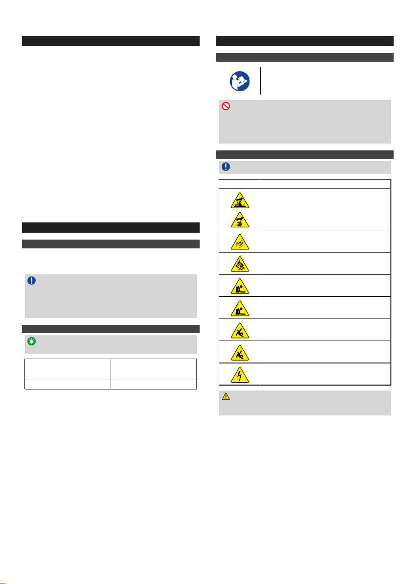
3. SAFETY . . . . . . . . . . . . . . . . . . . . . . . . . . . . . . . . . . . . . . . . . . . . . . . . . . . . . . . . . . . . . . . . . . . . . . . . . . . . . . . . . . . . . . . . . . . . . . . . . . . . . . . . . . . . . . . . . 2
3.1. Warning and precaution . . . . . . . . . . . . . . . . . . . . . . . . . . . . . . . . . . . . . . . . . . . . . . . . . . . . . . . . . . . . . . . . . . . . . . . . . . . . . . . . . . . . . . . . . . . 2
3.2. Risks . . . . . . . . . . . . . . . . . . . . . . . . . . . . . . . . . . . . . . . . . . . . . . . . . . . . . . . . . . . . . . . . . . . . . . . . . . . . . . . . . . . . . . . . . . . . . . . . . . . . . . . . . . 2
3.3. Warning stickers maintenance . . . . . . . . . . . . . . . . . . . . . . . . . . . . . . . . . . . . . . . . . . . . . . . . . . . . . . . . . . . . . . . . . . . . . . . . . . . . . . . . . . . . . 3
3.4. Recommendations . . . . . . . . . . . . . . . . . . . . . . . . . . . . . . . . . . . . . . . . . . . . . . . . . . . . . . . . . . . . . . . . . . . . . . . . . . . . . . . . . . . . . . . . . . . . . . . 3
3.4.1. Washing . . . . . . . . . . . . . . . . . . . . . . . . . . . . . . . . . . . . . . . . . . . . . . . . . . . . . . . . . . . . . . . . . . . . . . . . . . . . . . . . . . . . . . . . . . . . . . 3
3.4.2. Parking . . . . . . . . . . . . . . . . . . . . . . . . . . . . . . . . . . . . . . . . . . . . . . . . . . . . . . . . . . . . . . . . . . . . . . . . . . . . . . . . . . . . . . . . . . . . . . . 3
4. Operation . . . . . . . . . . . . . . . . . . . . . . . . . . . . . . . . . . . . . . . . . . . . . . . . . . . . . . . . . . . . . . . . . . . . . . . . . . . . . . . . . . . . . . . . . . . . . . . . . . . . . . . . . . . . . . . . 3
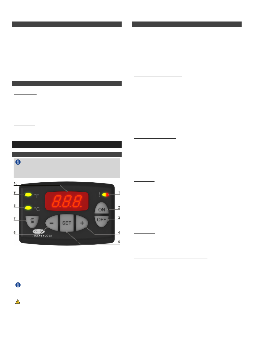
4.1. Cab command description . . . . . . . . . . . . . . . . . . . . . . . . . . . . . . . . . . . . . . . . . . . . . . . . . . . . . . . . . . . . . . . . . . . . . . . . . . . . . . . . . . . . . . . . . 3
4.2. Operation Principle . . . . . . . . . . . . . . . . . . . . . . . . . . . . . . . . . . . . . . . . . . . . . . . . . . . . . . . . . . . . . . . . . . . . . . . . . . . . . . . . . . . . . . . . . . . . . . . 3
4.2.1. In Road mode . . . . . . . . . . . . . . . . . . . . . . . . . . . . . . . . . . . . . . . . . . . . . . . . . . . . . . . . . . . . . . . . . . . . . . . . . . . . . . . . . . . . . . . . . 3
4.2.2. In Standby mode (optional kit) . . . . . . . . . . . . . . . . . . . . . . . . . . . . . . . . . . . . . . . . . . . . . . . . . . . . . . . . . . . . . . . . . . . . . . . . . . . . 3
4.2.3. Temperature control . . . . . . . . . . . . . . . . . . . . . . . . . . . . . . . . . . . . . . . . . . . . . . . . . . . . . . . . . . . . . . . . . . . . . . . . . . . . . . . . . . . . 3
4.2.4. Defrost . . . . . . . . . . . . . . . . . . . . . . . . . . . . . . . . . . . . . . . . . . . . . . . . . . . . . . . . . . . . . . . . . . . . . . . . . . . . . . . . . . . . . . . . . . . . . . . 3
4.2.5. Heating . . . . . . . . . . . . . . . . . . . . . . . . . . . . . . . . . . . . . . . . . . . . . . . . . . . . . . . . . . . . . . . . . . . . . . . . . . . . . . . . . . . . . . . . . . . . . . . 3
4.2.6. Control components (by cab command) . . . . . . . . . . . . . . . . . . . . . . . . . . . . . . . . . . . . . . . . . . . . . . . . . . . . . . . . . . . . . . . . . . . . 3
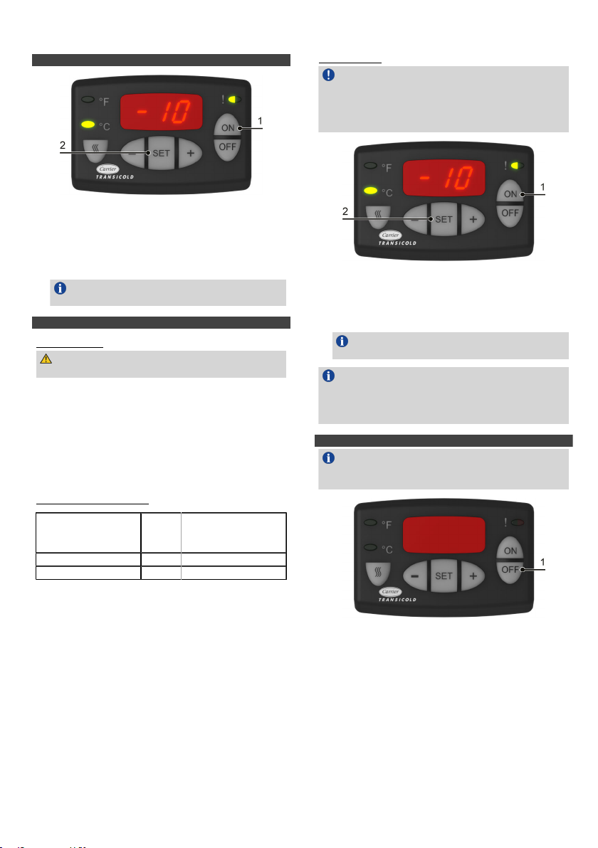
4.3. Start the unit in Road mode . . . . . . . . . . . . . . . . . . . . . . . . . . . . . . . . . . . . . . . . . . . . . . . . . . . . . . . . . . . . . . . . . . . . . . . . . . . . . . . . . . . . . . . 4
4.4. Start the unit in Standby mode (optional kit) . . . . . . . . . . . . . . . . . . . . . . . . . . . . . . . . . . . . . . . . . . . . . . . . . . . . . . . . . . . . . . . . . . . . . . . . . . 4
4.4.1. Introduction . . . . . . . . . . . . . . . . . . . . . . . . . . . . . . . . . . . . . . . . . . . . . . . . . . . . . . . . . . . . . . . . . . . . . . . . . . . . . . . . . . . . . . . . . . . 4
4.4.2. Standby guideline chart . . . . . . . . . . . . . . . . . . . . . . . . . . . . . . . . . . . . . . . . . . . . . . . . . . . . . . . . . . . . . . . . . . . . . . . . . . . . . . . . . 4
4.4.3. Procedure . . . . . . . . . . . . . . . . . . . . . . . . . . . . . . . . . . . . . . . . . . . . . . . . . . . . . . . . . . . . . . . . . . . . . . . . . . . . . . . . . . . . . . . . . . . . 4
4.5. Stop the unit . . . . . . . . . . . . . . . . . . . . . . . . . . . . . . . . . . . . . . . . . . . . . . . . . . . . . . . . . . . . . . . . . . . . . . . . . . . . . . . . . . . . . . . . . . . . . . . . . . . . 4
4.6. Adjust the setpoint temperature . . . . . . . . . . . . . . . . . . . . . . . . . . . . . . . . . . . . . . . . . . . . . . . . . . . . . . . . . . . . . . . . . . . . . . . . . . . . . . . . . . . . 5
4.7. Change display brightness . . . . . . . . . . . . . . . . . . . . . . . . . . . . . . . . . . . . . . . . . . . . . . . . . . . . . . . . . . . . . . . . . . . . . . . . . . . . . . . . . . . . . . . . 5
4.8. Change Defrost parameters . . . . . . . . . . . . . . . . . . . . . . . . . . . . . . . . . . . . . . . . . . . . . . . . . . . . . . . . . . . . . . . . . . . . . . . . . . . . . . . . . . . . . . . 5
4.9. Display unit data . . . . . . . . . . . . . . . . . . . . . . . . . . . . . . . . . . . . . . . . . . . . . . . . . . . . . . . . . . . . . . . . . . . . . . . . . . . . . . . . . . . . . . . . . . . . . . . . 5
4.10. Set user function . . . . . . . . . . . . . . . . . . . . . . . . . . . . . . . . . . . . . . . . . . . . . . . . . . . . . . . . . . . . . . . . . . . . . . . . . . . . . . . . . . . . . . . . . . . . . . . 6
5. Alarms . . . . . . . . . . . . . . . . . . . . . . . . . . . . . . . . . . . . . . . . . . . . . . . . . . . . . . . . . . . . . . . . . . . . . . . . . . . . . . . . . . . . . . . . . . . . . . . . . . . . . . . . . . . . . . . . . . 6
5.1. Display alarm list . . . . . . . . . . . . . . . . . . . . . . . . . . . . . . . . . . . . . . . . . . . . . . . . . . . . . . . . . . . . . . . . . . . . . . . . . . . . . . . . . . . . . . . . . . . . . . . . 6
5.2. Alarm list . . . . . . . . . . . . . . . . . . . . . . . . . . . . . . . . . . . . . . . . . . . . . . . . . . . . . . . . . . . . . . . . . . . . . . . . . . . . . . . . . . . . . . . . . . . . . . . . . . . . . . . 6
5.2.1. Direct access . . . . . . . . . . . . . . . . . . . . . . . . . . . . . . . . . . . . . . . . . . . . . . . . . . . . . . . . . . . . . . . . . . . . . . . . . . . . . . . . . . . . . . . . . . 6
6. Maintenance . . . . . . . . . . . . . . . . . . . . . . . . . . . . . . . . . . . . . . . . . . . . . . . . . . . . . . . . . . . . . . . . . . . . . . . . . . . . . . . . . . . . . . . . . . . . . . . . . . . . . . . . . . . . . 7
6.1. Introduction . . . . . . . . . . . . . . . . . . . . . . . . . . . . . . . . . . . . . . . . . . . . . . . . . . . . . . . . . . . . . . . . . . . . . . . . . . . . . . . . . . . . . . . . . . . . . . . . . . . . . 7
6.2. Maintenance Schedule . . . . . . . . . . . . . . . . . . . . . . . . . . . . . . . . . . . . . . . . . . . . . . . . . . . . . . . . . . . . . . . . . . . . . . . . . . . . . . . . . . . . . . . . . . . . 7
7. RECOMMENDATION . . . . . . . . . . . . . . . . . . . . . . . . . . . . . . . . . . . . . . . . . . . . . . . . . . . . . . . . . . . . . . . . . . . . . . . . . . . . . . . . . . . . . . . . . . . . . . . . . . . . . . 7
7.1. Before Loading . . . . . . . . . . . . . . . . . . . . . . . . . . . . . . . . . . . . . . . . . . . . . . . . . . . . . . . . . . . . . . . . . . . . . . . . . . . . . . . . . . . . . . . . . . . . . . . . . . 7
7.2. When Loading . . . . . . . . . . . . . . . . . . . . . . . . . . . . . . . . . . . . . . . . . . . . . . . . . . . . . . . . . . . . . . . . . . . . . . . . . . . . . . . . . . . . . . . . . . . . . . . . . . 7
8. RECOMMENDED TRANSPORT TEMPERATURES . . . . . . . . . . . . . . . . . . . . . . . . . . . . . . . . . . . . . . . . . . . . . . . . . . . . . . . . . . . . . . . . . . . . . . . . . . . . . . 8
9. 24H ASSISTANCE . . . . . . . . . . . . . . . . . . . . . . . . . . . . . . . . . . . . . . . . . . . . . . . . . . . . . . . . . . . . . . . . . . . . . . . . . . . . . . . . . . . . . . . . . . . . . . . . . . . . . . . 8


1
62-12263
NEOS 200e Cab Command and Decals

1. Introduction
This guide has been prepared for the operator of Carrier Transicold re-
frigeration units. It contains basic instructions for the daily operation of
the refrigeration unit as well as safety information, troubleshooting tips
and other information that will help you to deliver the load in the best
possible condition.
Please take the time to read the information contained in this booklet
and refer to it whenever you have a question about the operation of your
Carrier Transicold unit. This manual refers to the standard model. Some
options may not appear in it, and in such cases, you are requested to
consult your Carrier Transicold Service Center.
Your refrigeration unit has been engineered to provide long, trouble-free
performance when it is properly operated and maintained. The checks
outlined in this guide will help to minimize on the road problems. In addi-
tion, a comprehensive maintenance program will help to ensure that the
unit continues to operate reliably. Such a maintenance program will also
help to control operating costs, increase the unit's working life, and im-
prove performance.
When having your unit serviced, be sure to specify genuine Carrier Tran-
sicold replacement parts for the highest quality and best reliability.
At Carrier Transicold, we are continually working to improve the products
that we build for our customers. As a result, specifications may change
without notice.
2. Identification and Noise Level
2.1. Nameplate
Each unit is identified by a nameplate (A) attached to the frame of the
unit. The nameplate identifies the complete model number of the unit,
the Serial Number (B) and some other information.
If a problem occurs, please refer to the information on this plate,
and make a note of the model and Serial Number (B) before
calling for assistance.
This information will be needed when you contact a techni-
cian so that he may properly assist you.
2.2. Noise Level
The "Noise level" decal (C) indicates the noise level in Lwa
(sound power level).
Unit
Maximum Sound Power
Level LWA(dB)
NEOS 200e 57
3. Safety
3.1. Warning and Precaution
This manual contains safety and service instructions
to follow in order to prevent any accident. Some of
following decals have been placed on the product
for your SAFETY.
•NEVER manipulate cab command when driving.
•NEVER intervene on the unit for any service or maintenance
operation, contact your Carrier Service Center.
•NEVER remove safety elements (grill, skin, metal sheet). If
damaged, contact your Service Center for replacement.
3.2. Risks
Call 911 in case of accident or emergency.
GENERAL RISKS
Burning with hot and cold
Cuttings
Noise level
Exhaust gas: DO NOT use the unit in a closed space
Asphyxiation: leave the doors open when working
inside the body
Risk of slipping going up in the body - ice on the
floor
Risk of slipping going out of the body - gas / oil on
the floor - leak of refrigerant
Electrical risks – when connecting and disconnecting
standby plug
It is essential to shut down the compartment when the doors are
open if you are not equipped of plastic curtains, in order to
maintain the temperature of this compartment.
2
62-12263

3.3. Warning Label Maintenance
1. Keep the warning pictograms clean and without any obstruction
material.
2. Clean the pictograms with water and soap and wipe them with soft
fabric.
3. Replace damaged or missing pictograms with new pictograms
available in Carrier network.
4. If a component having a pictogram is replaced by a new one, be sure
that the new component has the right pictogram.
5. Place a warning pictogram by applying it on a dry surface. Press to
external sides to eliminate air bubbles.
3.4. Recommendations
3.4.1. Washing
•When washing the vehicle, DO NOT point the high-pressure
water under the skin.
•DO NOT spray water on electric components.
•When washing inside the compartment, DO NOT spray the fan with
detergent.
3.4.2. Parking
Do not park your vehicle in a slope above 10% in order to avoid bad
water drain.
4. Operation
4.1. Cab Command Description
This functional accessory simplifies all control operations. From
his seat, the driver can carry out all control operations: shutdown,
automatic start-up, adjusting the temperature setpoint, defrost,
etc.
6. - key
7. MANUAL DEFROST key
8. °C TEMPERATURE led
9. °F TEMPERATURE led
1. UNIT OPERATING DATA LED¹
2. ON key
3. OFF key
4. + key
5. SET key 10. Display
(¹) Green: normal cycling (left half) / Red: malfunction (right half) If
the cab command is built into the vehicle control panel it must
be located as far as possible from the heating ducts.
6. Maximum temperature of exposure: (158°F (70°C.)
4.2. Operation Principle
After starting-up the refrigeration unit by pressing the ON key, unit start-
up and shut down are automatic.
4.2.1. Road Mode
The NEOS 200e is an all-electric refrigeration unit, powered by the
vehicle battery (alternator.)
The unit automatically shuts down when the engine is switched OFF with
the ignition key.
4.2.2. Standby Mode (Optional)
NEOS 200e units are powered by a standby module reducing the 230
VAC into 12 VDC.
The power network connection is detected by the standby module which
automatically starts up the unit in standby mode.
Double power supply buzzer: If the ignition key is switched ON while the
unit is connected to the power network or if you connect the
standby plug while unit is running a buzzer alarm will sound
indicating double power supply. Unit stops.
In all cases the unit can be completely shut down manually by pressing
the OFF key on the cab command.
4.2.3. Temperature Control
As soon as the setpoint temperature has been reached, temperature con-
trol is obtained by the start-up and shut down of the compressor.
The condenser and evaporator fan(s) cut out during regulation.
When transporting fragile loads such as fresh meat, vegetables and
cheese, it is possible to program the microprocessor to obtain
continuous ventila-tion by the evaporator during regulation (refer to
Section 4.10, “Set user function”).
4.2.4. Defrost
•Defrost operation is fully automatic but can be manually controlled
by pressing the MANUAL DEFROST key (if enabled by the defrost
thermostat).
•Defrost cycles are fully controlled by the integrated microprocessor.
•During the defrost cycle, the evaporator fan(s) shut down.
•The condenser fan is controlled by the microprocessor.
•Defrost cycle termination is controlled by a defrost thermostat.
•During the defrost cycle, the cab command display indicates "dF".
4.2.5. Heating
•Heating is provided by hot gas system.
•The evaporator fan(s) operates & the condenser fan is controlled by
the microprocessor.
4.2.6. Control Components (by Cab Command)
•Unit start
•Shut down.
•Selection of road or standby operation.
•Manual defrost.
•Thermostat control.
•Error messages in the event of unit malfunction.
•Programming to customize unit operation to your own requirements.
3
62-12263

4.3. Starting the Unit in Road Mode
1. Start the vehicle engine.
2. Press the ON key (1) to start the unit.
Start-up time is delayed for 40 seconds. Compartment temperature
is then displayed.
3. Press the SET key (2) to check if the setpoint matches your need
and adjust it if needed.
Refer to Section 4.6, “Adjust the setpoint temperature” to get
the procedure.
4.4. Starting the Unit in Standby Mode (Option)
4.4.1. Introduction
For safe & reliable operation in Standby mode, it is important to
consider the following guidelines:
A. ALWAYS check that the unit is OFF from the cab command before
connecting or disconnecting it from the power source.
B. The unit connection cable must be fitted with a ground connection.
The cable must be connected to earth.
C. On the 400 V supply, the unit MUST BE CONNECTED to a high
sensibility (30 mA) differential protection.
D. Operations on the 400 V supply for the unit must only be carried out
by authorized personnel.
E. The user is liable for ensuring that the above measures are taken.
4.4.2. Standby Guideline Chart
Operating voltage Max.
current
Standardized exten-
sion cable H.07.RNF
Maximum 30m
230V/1/50Hz 8.5 A 1,5 mm²
230V/1/60Hz 6.8 A 1,5 mm²
4.4.3. Prrocedure
Before Starting
•On the power network, check that the type of current
corresponds to the characteristics of the unit, see Section
4.4.2, “Standby guideline chart”.
•On the unit: check if the power network is properly connected.
1.
2.
Press the ON key (1) to start the unit.
Start-up time is delayed for 10 seconds. Compartment temperature
is then displayed.
Press the SET key (2) to check if the setpoint matches your need
and adjust it if needed.
Refer to Section 4.6, “Adjust the setpoint temperature” to get
the procedure.
In the event of difficulty on start-up, check that:
•Network supply is ok.
•The temperature set on the cab command has not been
affected.
4.5. Stopping the Unit
•For a short stop (ex. delivery): simply switch OFF the vehicle
ignition.
•For a long stop: follow the instructions below.
1. Press the OFF key (1) to stop the unit.
4
62-12263

4.6. Adjusting Setpoint Temperature
When adjusting, if no key is pressed within five seconds the
system returns to compartment temperature display. All changes
are saved.
1. On default screen, press the SET key (2) to display the actual
setpoint temperature.
2. Press the + key (1) or - key (3) to adjust the temperature.
3. Press the SET key (2) to validate the change & return to
compartment temperature display.
4.7. Changing Display Brightness
1. On default screen, hold for 3 seconds the + key (1) to increase or -
key (2) to decrease the display brightness.
4.8. Changing Defrost Parameters
When adjusting, if no key is pressed within five seconds the
system returns to compartment temperature display. All changes
are saved.
1. Press the OFF key (2) to stop the unit first .
2. Press and hold together the MANUAL DEFROST key (6) & ON key
(1) to access defrost parameters.
The currently selected parameter is displayed.
3. Press the + key (3) or - key (5) to select the desired parameter.
4. Press the SET key (4) to validate the change.
Available
parameter Description
0.0 Inhibit defrost function
Aut (coef-
ficient 1)
Microprocessor-optimized automatic defrost
according to type of cargo transported (variable
interval
0H / 1H /
2H / 3H /
4H / 5H / 6H
Fixed defrost interval in hours
4.9. Displaying Unit Data
When adjusting, if no key is pressed within five seconds the
system returns to compartment temperature display. All changes
are saved.
1. Hold the SET key (2) during five seconds to access unit data.
2. Press the SET key (2) again to scroll through the list.
3. Press the + key (1) or - key (3) on the displayed data to see
additional information (if any).
Order Display Description
AXX Active alarms
1PXX
Inactive alarms
Refer to Section 5.2, “Alarm list”.
2X.Y.Z
Software version
Cab command version
3XXX Road hour meter
4XXX Standby hour meter
5
62-12263

4.10. Setting User Function
When adjusting, if no key is pressed within five seconds the
system returns to compartment temperature display. All changes
are saved.
1. On default display, press together the DEFROST (4) / + (1) / - (3) keys
to access the functional parameters.
2. Press the + key (1) or - key (3) on the desired function to change its
value.
3. Press the SET key (2) to scroll through the list and validate changes.
Function Available selection
Minimum setpoint
lock value
-29°C
(-20°F)* -20°C (-4°F) 0°C (32°F)
Differential parame-
ter
dF.1
(1°C/1.8°F)
dF.2
(2°C/3.6°F)*
dF.3
(3°C/5.4°F)
Evaporator fan con-
tinuous run (status
during regulation/null
mode)
F.OF*F.On /
(*) Indicates factory setting.
5. Alarms
5.1. Displaying Alarm List
If no key is pressed within five seconds the system returns to
compartment temperature display.
1. Hold the SET key (2) for five seconds to access the alarm
list.
2. Press the + key (1) or - key (3) to scroll through the list.
AXX: current malfunctions
PXX: past malfunctions
5.2. Alarm List
SEVERITY OR THE ALARM
The unit can run without risk. Go to Service Center for
maintenance.
The vehicle can still drive but the unit is automatically
switched OFF. Go to Service Center to check
function-ing.
Immediately stop the vehicle. The unit cannot run. Call
Service Center.
Malfunction - Red LED flashes
Severity Code Description
A00 No malfunction. Unit in operational
A01 High Pressure or Low Pressure switch
ac-tive
A02 High Pressure or Low Pressure switch
ac-tive
A03 DC electrical motor overheated (displayed
alternatively)
A04 Road compressor clutch fault
A06 Condenser fan motor fault
A07 Evaporator fan motor fault
A09 Hot Gas Valve fault (HGV or HGS1)
A11 Hot Gas Valve fault (MHV or HGS2)
A12 High temperature alarm
A13 Low temperature alarm
A14 Defrost fail
A15 setpoint adjusted out of range -29°
C /+30°C (-20°F / 86°F)
5.2.1. Direct Access
Direct display malfunction messages are displayed instead
of temperature read-out as soon as the malfunction is
detected and remain displayed as long as malfunction persists.
The unit does not run until the malfunction has disappeared or
been corrected.
Direct Access Alarms
Severity Code Description
EE Malfunction: evaporator temperature probe
(open circuit)
bAt Battery low voltage alarm
Err Incorrect setpoint setting
---
Setpoint out of the "Minimum / Maximum
setpoint lock value" range set in user func-
tion (but in the range -29°C (-20°F) / +30°C
(86°F))
E2P Wrong function setting / Loss of data - Micro
not starting up / Stays in BOOT (Init phase)
SE Maintenance needed.
SE alarm will be displayed every 1000 hours alternatively with
compartment T° and can be canceled by Carrier Transicold
Service Center.
6
62-12263

6. Maintenance
6.1. Introduction
A comprehensive maintenance program will help to ensure that the unit
continues to operate reliably. Such a maintenance program will also help
to control operating costs, increase the unit's working life, and improve
performance.
IMPORTANT TO READ AND FOLLOW
Regular maintenance includes a quick overview of the unit
from a Safety perspective. Service Technician must pay par-
ticular attention, but not exclusively to: nuts and bolts tight-
ening (replacing if missing), electrical wires, harnesses, fuel
lines routing (repairing or replacing if needed), doors, skins
grills, panels conditions (repairing or replacing if needed).
Confirmation of such operations can be detailed on request.
All maintenance services must be done by a technician trained
on Carrier products respecting all safety and quality standards of
Carrier.
6.2. Maintenance Schedule
Hours Service Type
Displayed Real Initial
service Service A Service B
10 100 X
100 1000 X
200 2000 X X
300 3000 X
400 4000 X X
500 5000 X
600 6000 X X
700 7000 X
7. Product Loading
This unit is not designed to carry special loads which emit
corrosive gas.
These kinds of products can impact unit performance, and
seriously reduce component lifetime.
Please contact us if such products need to be carried.
•Proper air circulation in the compartment, air that can move
around and through the load, is a critical element in maintaining
product quality during transport. If air cannot circulate completely
around the load, hot spots or top freeze can occur.
•The use of pallets is highly recommended. When pallets are
loaded so air can flow freely through them to return to the
evaporator, the product is protected from heat passing through
the floor of the trailer. When using pallets, it is important to
refrain from stacking extra boxes on the floor at the rear of the
compartment as this will cut off the airflow.
•Product stacking is another important factor in protecting the
product. Products that generate heat, such as fruits and
vegetables, should be stacked so the air can flow through the
product to remove the heat. This is called "air stacking" the
product. Products that do not create heat, such as meats and
frozen products, should be stacked tightly in the center of the
compartment.
•All products should be kept away from the sidewalls of the
body, allowing air to flow between the body and the load. This
prevents heat filtering through the walls from affecting the
product.
•It is important to check the temperature of the product being
loaded to ensure that it is at the correct temperature for
transport.
The refrigeration unit is designed to maintain the temperature of
the product at the temperature at which it was loaded; it is not
designed to cool a warm product.
7.1. Before Loading
•Pre-cool the compartment by lowering the temperature for
about 15 minutes.
•Evacuate the humidity existing inside the compartment
by carrying out a manual defrost. This can only take place
when enabled by the defrost thermostat (box temperature
lower than 37.4°F during pull down and 46.4°F during heating).
•Evaporator fans are protected by safety grilles. In the event of
heavy duty use of the unit, ice can accumulate on the grilles. It
is therefore recommended to clean them regularly by means of a
small brush. The operation MUST be done when the unit has
been SHUTDOWN.
7.2. During Loading
•Stop the unit (place START/RUN/OFF switch in the OFF
position.
•Check product temperature during loading.
•Ensure that the air returns and supply openings remain
unobstructed
•Leave approximately 4 to 5 inches between
load and compartment front wall for air
return to the unit.
•Leave at least 10 to 12 inches between the
top of the load and the ceiling to ensure
there is nothing to prevent air flow.
•Load product on pallets to provide free air
return to unit and improvement product
protection.
•Do not forget to close the doors.
•Before closing the doors, check your load once more and see
that nobody is shut inside the compartment.
For stationary utilization, we recommend placing the
compartment in the shade.
Never leave your unit more than a month without running.
Open the cooling compartment doors in case of extended stop.
7
62-12263

8. Recomnmended Transport Temperatures
Below are some general recommendations on product transport temper-
atures and operating modes for the unit. These are included for
reference only and should not be considered pre-emptive of the setpoint
required by the shipper or receiver. More detailed information can be
obtained from your Carrier Transicold dealer.
PRODUCT SETPOINT RANGE
Bananas 15°C 60°F
Fresh fruits and vegetables +4°C to +6°C +39°F to +43°F
Fresh meats and seafood +2°C +36°F
Dairy products +2°C to +6°C +36°F to +43°F
Ice -20°C -4°F
Frozen fruits and vegetables -18°C 0°F
Frozen meats and seafood -20°C -4°F
Ice cream -25°C -13°F
During delivery cycles that includes frequent stops and door
openings, it is recommended that the unit always be operated in
the continuous run mode to help ensure product quality.
It is essential to shut down the compartment during the periods
when the doors are open, in order to maintain the temperature of
the cargo in the other compartments and keep the unit operating
correctly.
•Location information for every Carrier Transicold dealer in North
America
•The nearest dealer from your present location
•Dealer look-up capability
•Dealer services (Trailer, Truck, APU, Mobile Support, etc.)
•Addresses
•Maps to easily find dealers
•Directions and navigation to the dealerships
•Phone number and 24-hour emergency hotlines, where available
•Auto dialing
•Hours of operation
•Link to dealer website
•Ability to add dealers to Contacts
9. Emergency Road Service
8
62-12263
At Carrier Transicold, we are working hard to give you complete
service when and where you need it. That means a worldwide
network of dealers that offer 24-hour emergency service. These
service centers are manned by factory-trained service personnel
and backed by extensive parts inventories that will assure you of
prompt repair.
Should you experience a problem with your unit during transit,
follow your company's emergency procedure or contact the
nearest Carrier Transicold Service Center. Consult the Shortstop
Service Centers directory or visit www.trucktrailer.carrier.com and
click "Dealer Locator" to locate the service center nearest to you.
The Shortstop directory can be obtained from your Carrier
Transicold Dealer.
You can also download the Carrier Transicold North America
Truck/Trailer Dealer Locator App to your smart phone. The Dealer
Locator app provides:
To download the Carrier Transicold
North America Truck/Trailer Dealer
locator app, scan this QR code or go
directly to your App store and
search for Carrier Transicold Dealer
App. If you are unable to reach a
Carrier Transicold Dealer, call our
24-hour action line (800-448-1661).
We will do everything we can to
resolve your issue and get you back
on the road. .

9
62-12263

©2024 Carrier Corporation. Printed in USA 02/24
Carrier, Carrier Transicold is a registered trademark of Carrier Corporation.
North America
Carrier Transicold
700 Olympic Drive
Athens, GA 30601 USA
Central America and Mexico
Carrier Transicold
Ejercito Nacional 253-A Piso 5
Colonia Anahuac 11320 Mexico D.F.
WARNING: Breathing diesel engine exhaust exposes
you to chemicals known to the State of California to cause
cancer and birth defects or other reproductive harm.
• Always start and operate engine in a well-ventilated area.
• If in an enclosed area, vent the exhaust to the outside.
• Do not modify or tamper with the exhaust system.
• Do not idle the engine except as necessary.
For more information, go to www.P65warnings.ca.gov/diesel
Table of contents
Other Carrier Automobile Accessories manuals
Popular Automobile Accessories manuals by other brands

Kobo
Kobo VK022003AC1 Installation and instruction manual

Napier
Napier SPORTZ 57 Series manual

DV8 OFFROAD
DV8 OFFROAD D-JL-180014-SIL4 installation manual

GU Electronic
GU Electronic LandRover 2016-TD manual

Marquant
Marquant 441-069 installation instructions

AMP Research
AMP Research PowerStep 75155-01A installation guide