manuals.online logo
Brands
  1. Home
  2. •
  3. Brands
  4. •
  5. Kobo
  6. •
  7. Automobile Accessories
  8. •
  9. Kobo VK022003AC1 Quick guide

Kobo VK022003AC1 Quick guide

V1.1
Electric vehicle
smart charging station
Installation and instruction manual
Kobo New Energy
Product Model: VK022003AC1 s VK022007AC1
After-sales hot line: 400-820-8690
1. Technical parameters
Serial
number
Project Parameters
1
Product
model
VK022003AC1 VK022007AC1
2
Operating
voltage
220VAC±20%
3
Rated
current
16A 32A
4
Rated
power
3.5KW 7KW
5
Frequency
of
operation
50Hz±5%
6
Protection
level
IP55 (Outdoor)
7
Operating
temperatur
e
-40℃~+65℃
8
Ambient
humidity
95% no condensation
9
Use
altitude
≤2000m
10
Operating
instructions
LED BELT
2. Product structure
1. Charging station
cover
2. Swipe area 3. LED
4. Charging plug 5.Charging cable 6. Emergency Stop
Button
7.Charging station
base plate
Tip: Do not use the emergency stop button as a stop switch, if the emergency
stop is pressed, please reset it clockwise.
3. The operation step (swipe charge)
Step 1: Insert a plug
Remove the charging plug from the station and connect the vehicle AC charging
port. When the connection is successful, the blue light on the station flashes.
Step 2: Swipe
The user card will be distributed with the station, close to the station swipe area
1S or so and moved, the charging station will be the user card
authentication. If the right is successful, the buzzer on the station will prompt
and enter the charging state.
Step 3: Charging
When you begin the charging processing, the light on the station flashes green
Step 4: End of charging
The station indicator is constant in green when the vehicle is full yves to end
charging or when the user swipes again to end charging. Pull the charging
station out of the car and position it on the charging station. The indicator on
the station is constant in blue.
4. Light language description
Serial
numbe
r
Action/Status
Light
language
status
Light language
resolution
1 Standby
Blue is
always
bright
Standby
2 Put the station in.
Flashing
blue
Connected to
the end of the
car
3
Right pass (buzzer ring 1
time)
Flashing
blue
The right to pass
4
Authentication failure
(buzzer ring 2 times)
Flashing
blue
User card error
5 Charging
Green
flashing
Charging
6 The electricity is full Green solid
Charging
complete
7 Pull the station.
Blue is
always
bright
Standby
8 Fault Red flashing
Charging/device
failure
5. Factory inspection list
Serial
number
Check
the item
Acceptance criteria Results
1
Interior
appearan
ce
The wiring is correct, the screws are
fastened.
OK
2
Overall
appearan
ce
Visually free of appearance defects,
fully identified
OK
3
Electrical
inspectio
n
General on check, short-circuit check,
ground check
OK
4
Safety
Check
Insulation resistance and dielectric
strength
OK
5
Function
check
Power-on light with on-board charging
OK
6 Charging GB/T 20234.1-2015 OK
station GB/T 20234.2-2015
7
Accessori
es
package
Complete materials, no omissions OK
8
Packing
inspectio
n
Complete material, no visual defects OK
Qualified stamp:
6. Packing list
1, wall-mounted products
Serial
numbe
r
Name Specifications
Numbe
r Note
1 AC charging station
1
2 Product description
1
3 Self-sealing bag 1
4 Anti-theft screws
M4X10 with lock
core
2
5 Combining screws
M6X12 4
6 Bolt M6X16 4
7
Internal forced
expansion anchor
M6X25 4
8 Anti-theft wrench
T15 1
9 Mounting board 160X202X15 1
10 Support 15X20X110 2
11 Support 35X60X45 1
12
Plastic expansion
tube
CN5055A-6*30-PA 3
13 Self-tapping screw
Crosshead ST3.9 x
16
3
2, column-type products
Serial
numbe
r
Name Specifications
Numbe
r Note
1 AC charging station
1
2 Product description
1
3 Self-sealing bag 1
4 Combining screws
M6X12 4
5 Expansion bolts M8*100 4
6 Anti-theft screws
M4X10 with lock
core
3
7 Anti-theft wrench
T15 1
7. Installation guidance
8.1 Installation precautions
Before installing, read the installation instructions carefully, paying special
attention to the following:
1) This charging station installation needs to be carried out by professional and
technical personnel in strict accordance with the installation steps and
standards of construction. Non-qualified installation team, such as in the
installation process caused damage to the charging station or improper
installation of the charging station later use, are not eligible for our warranty
services.
2) If the site to be installed is under construction, do not install immediately.
Prevent damage to charging stations in building materials, dust and paint.
3) Charging station use dedicated power supply or interface, must be good
ground, fire zero wiring is strictly prohibited to reverse, before wiring please
ensure power failure.
4) When installing, wear protective gloves to prevent scratching.
5) Please use random attachments for installation, the installation of expansion
bolts, expansion bolts and wall holes must be closely coordinated, strictly
prohibit edgy drilling, so as not to expand the bolt loose, resulting in an
accidental fall of the charging station.
6) Before installation, please follow the packing list to check that the
components are complete. If there are defects, please contact the Company in a
timely manner.
8.2 Installation Tool List
1) Wall-mounted products
Serial Name Number
Note
1 Electric impact drill and impact 1 Φ8
2 Scale (5m) 1 put
3 Electrician Gloves 1 pay
4 Cross Screwdriver 1 put 3#
5 Inner hex wrench 1 5mm
6 PVC insulation tape 1 volume
7 T15 Anti-Theft Wrench 1
2) Pillar products
Serial Name Number
Note
1 Electric impact drill and impact 1 Φ12
2 Inner hex wrench 1 put 5mm
3 Electrician Gloves 1 pay
4 T15 Anti-Theft Wrench 1
5 Open wrench 1 14*13
6 PVC insulation tape 1 volume
8.3 Positioning Installation
The corresponding fastening bolts should be prepared prior to installation, with
the following parameters:
Screw model Num
ber
Use (use)
M6X25 (Inside Force
Expansion Anchor)
4 Installation of wall panels to walls
/ columns to the base
Use the wall mount/column to determine the installation position
(recommended height of 1250mm), and then shock the drill punch ingle to
mount the wall mount plate to the wall wall/the column to the
specified position.
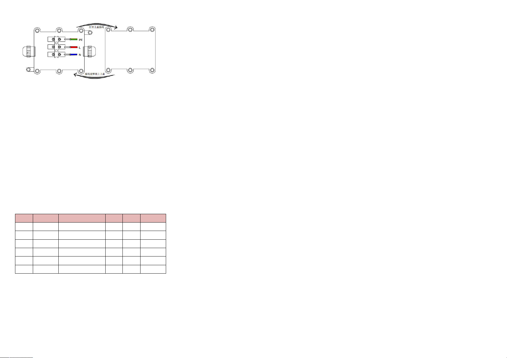
8. Installation wiring instructions
After removing the 6 screws on the cover of the charging station junction box,
unscrew the waterproof connector under the terminal box, penetrate the
incoming cable into the inside of the terminal box, and, as indicated in the
following image, the incoming cable is attached to the corresponding terminal
and the screws of the terminal row are tightened with a tool.
The wiring needs to meet the following requirements:
1) The charging station should have a separate distribution circuit and should
not be shared with other electrical products.
2) 3.5KW station inlet end cable requirements of 2.5mm2, 7.0KW inlet cable
requirements of 6mm2, inlet crimping terminal.
3) In order to prevent electric shock, we should ensure that the input ground
securely grounded in accordance with the installation instructions for
installation, prohibit the use of two or three-core plugs in the front of the
charging station, any consequences, the Division is not responsible.
9. After-sales maintenance records
For non-human factors, non-force majeure caused by equipment failure /
function failure, can enjoy our after-sales warranty services, please consumers
carefully fill in our warranty card.
Serial Fault On-site maintenance Time
Custo After-
1
2
3
4
5
6
Customer Name:
Contact Phone:
Installation address: Installation time:
Thank you for your patience during our service and wish you a pleasant charge!

This manual suits for next models

1

Popular Automobile Accessories manuals by other brands

Westfalia Automotive AD65U Installation and operating instructions

Westfalia Automotive

Westfalia Automotive AD65U Installation and operating instructions

DVB SPJL-02 installation manual

DVB

DVB SPJL-02 installation manual

Quadratec QuadraTop Adventure Top S manual

Quadratec

Quadratec QuadraTop Adventure Top S manual

TAUBENREUTHER 16-5910 manual

TAUBENREUTHER

TAUBENREUTHER 16-5910 manual

Outlust 17374 user manual

Outlust

Outlust 17374 user manual

Cruz Evo Rack Pro Assembly instructions

Cruz

Cruz Evo Rack Pro Assembly instructions

KAPSCH G4P Mounting instructions

KAPSCH

KAPSCH G4P Mounting instructions

Standby P1 PANEL user manual

Standby

Standby P1 PANEL user manual

Metra Electronics 95-5025 installation instructions

Metra Electronics

Metra Electronics 95-5025 installation instructions

ARB 819105 quick start guide

ARB

ARB 819105 quick start guide

Maxxhaul 70074 Instruction manual & parts list

Maxxhaul

Maxxhaul 70074 Instruction manual & parts list

Monacor CARPOWER CAP-12LED manual

Monacor

Monacor CARPOWER CAP-12LED manual

Laser NAVC-BHUD-982 user manual

Laser

Laser NAVC-BHUD-982 user manual

Technaxx TX-168 user manual

Technaxx

Technaxx TX-168 user manual

Classic Accessories QuadGear Extreme ATV EVOLUTION FRONT RACK... quick start guide

Classic Accessories

Classic Accessories QuadGear Extreme ATV EVOLUTION FRONT RACK... quick start guide

Cruz Alu-Rack L 13-120 Assembly instructions

Cruz

Cruz Alu-Rack L 13-120 Assembly instructions

Aries P2066 installation manual

Aries

Aries P2066 installation manual

Goji G10WMAG19 instruction manual

Goji

Goji G10WMAG19 instruction manual

manuals.online logo
manuals.online logoBrands
  • About & Mission
  • Contact us
  • Privacy Policy
  • Terms and Conditions

Copyright 2025 Manuals.Online. All Rights Reserved.