manuals.online logo
Brands
  1. Home
  2. •
  3. Brands
  4. •
  5. Carrier
  6. •
  7. Heat Pump
  8. •
  9. Carrier 50JZ030 Assembly Instructions

Carrier 50JZ030 Assembly Instructions

This manual suits for next models

5

Other Carrier Heat Pump manuals

Carrier 25HBA3 Series Operation manual

Carrier

Carrier 25HBA3 Series Operation manual

Carrier AIR COOLED SPLIT SYSTEM 38AQS008 Operation manual

Carrier

Carrier AIR COOLED SPLIT SYSTEM 38AQS008 Operation manual

Carrier Elegant 53QFJ36 User manual

Carrier

Carrier Elegant 53QFJ36 User manual

Carrier CNPVP, CNRVP User manual

Carrier

Carrier CNPVP, CNRVP User manual

Carrier XCT7 40VD005-024L-7E-QEE Installation instructions

Carrier

Carrier XCT7 40VD005-024L-7E-QEE Installation instructions

Carrier AquaSnap 61AF-B Manual

Carrier

Carrier AquaSnap 61AF-B Manual

Carrier Omnizone 09XC06 Dimensions and installation guide

Carrier

Carrier Omnizone 09XC06 Dimensions and installation guide

Carrier 38YXA User manual

Carrier

Carrier 38YXA User manual

Carrier 80AWX Series User manual

Carrier

Carrier 80AWX Series User manual

Carrier 38QW User manual

Carrier

Carrier 38QW User manual

Carrier 50JZ 024-060 Assembly Instructions

Carrier

Carrier 50JZ 024-060 Assembly Instructions

Carrier 25VNA User manual

Carrier

Carrier 25VNA User manual

Carrier 50RQ Operation manual

Carrier

Carrier 50RQ Operation manual

Carrier 38QB Dimensions and installation guide

Carrier

Carrier 38QB Dimensions and installation guide

Carrier 50VT-B Instruction Manual

Carrier

Carrier 50VT-B Instruction Manual

Carrier 50ZHA Assembly Instructions

Carrier

Carrier 50ZHA Assembly Instructions

Carrier Infinity 50CR Series Instruction Manual

Carrier

Carrier Infinity 50CR Series Instruction Manual

Carrier WeatherMaster 50HCQA07 User manual

Carrier

Carrier WeatherMaster 50HCQA07 User manual

Carrier 50KQ006-019 Dimensions and installation guide

Carrier

Carrier 50KQ006-019 Dimensions and installation guide

Carrier CPCRKHTR003A00 User manual

Carrier

Carrier CPCRKHTR003A00 User manual

Carrier 50NQ Dimensions and installation guide

Carrier

Carrier 50NQ Dimensions and installation guide

Carrier 48XZ Guide User manual

Carrier

Carrier 48XZ Guide User manual

Carrier aquazone 50RTG Dimensions and installation guide

Carrier

Carrier aquazone 50RTG Dimensions and installation guide

Carrier 25HHA4 User manual

Carrier

Carrier 25HHA4 User manual

Popular Heat Pump manuals by other brands

Daikin RXL12QMVJU Service manual

Daikin

Daikin RXL12QMVJU Service manual

AIREDALE BluCube CUR092V16-1CO-0 Installation and maintenance manual

AIREDALE

AIREDALE BluCube CUR092V16-1CO-0 Installation and maintenance manual

Calyenty RBH 125 Customer's manual

Calyenty

Calyenty RBH 125 Customer's manual

GRE HPGI50 owner's manual

GRE

GRE HPGI50 owner's manual

Hayward SUMHEAT HP5131DT3 Installation instructions manual

Hayward

Hayward SUMHEAT HP5131DT3 Installation instructions manual

REMKO SQW 400 Electrical wiring

REMKO

REMKO SQW 400 Electrical wiring

Sanyo SAP120FCH Service manual

Sanyo

Sanyo SAP120FCH Service manual

Daikin EHYHBH05AA Operation manual

Daikin

Daikin EHYHBH05AA Operation manual

Panasonic WH-SDF03E3E5 Design handbook

Panasonic

Panasonic WH-SDF03E3E5 Design handbook

Airxcel 45000 Series Installation, operation and maintenance instructions

Airxcel

Airxcel 45000 Series Installation, operation and maintenance instructions

Mitsubishi Electric PUZ-SWM60VAA Service manual

Mitsubishi Electric

Mitsubishi Electric PUZ-SWM60VAA Service manual

Dimplex LI 16I-TUR Installation and operating instruction

Dimplex

Dimplex LI 16I-TUR Installation and operating instruction

Mitsubishi Electric EHSE-YM9EC Service manual

Mitsubishi Electric

Mitsubishi Electric EHSE-YM9EC Service manual

TGM CTV14CN018A Technical manual

TGM

TGM CTV14CN018A Technical manual

Kokido K2O K880BX/EU Owner's manual & installation guide

Kokido

Kokido K2O K880BX/EU Owner's manual & installation guide

Viessmann VITOCAL 300-G PRO Type BW 2150 Installation and service instructions

Viessmann

Viessmann VITOCAL 300-G PRO Type BW 2150 Installation and service instructions

Viessmann KWT Vitocal 350-G Pro Series Installation and service instructions for contractors

Viessmann

Viessmann KWT Vitocal 350-G Pro Series Installation and service instructions for contractors

Weishaupt WWP L 7 Installation and operating instruction

Weishaupt

Weishaupt WWP L 7 Installation and operating instruction

manuals.online logo
manuals.online logoBrands
  • About & Mission
  • Contact us
  • Privacy Policy
  • Terms and Conditions

Copyright 2025 Manuals.Online. All Rights Reserved.

50JZ
Single-Package Electric Heat Pump Unit
with Puron® (R-410A) Refrigerant
A Guide To Operating and Maintaining Your
Single-Package Electric Heat Pump Unit
NOTE TO INSTALLER
This manual should be left with the equipment owner.
Do not store or use gasoline or other flammable vapors and
liquids in the vicinity of this or any other appliance. Failure to
follow this warning could result in fire, serious injury, or
death.
Do not use this unit if any part has been under water.
Immediately call a qualified service technician to inspect the
unit and to replace any part of the control system which has
been under water. Failure to follow this warning could result
in electrical shock, fire, serious injury, or death.
Before performing recommended maintenance, be sure the
main power switch to unit is turned off. Electric shock could
cause serious injury or death.
TO START UNIT
1. Turn on the electrical power supply to unit.
2. Select temperature and set SYSTEM switch or MODE control
to desired mode.
TO SHUT UNIT OFF
If unit is being shut down because of a malfunction, call your
dealer as soon as possible.
1. Set system SWITCH or MODE control to OFF.
2. Turn off the electrical power supply to unit.
OPERATING YOUR HEAT PUMP UNIT
The operation of your heat pump system is controlled by the
indoor thermostat. You simply adjust the thermostat and it
maintains the indoor temperature at the level you select. Most
thermostats for heat pump systems have 3 controls: a temperature
control selector, a FAN control, and a SYSTEM or MODE control.
Refer to your thermostat owner’s manual for more information.
Step 1—Cooling Mode
With the SYSTEM or MODE control set to COOL, your heat
pump will run in cooling mode until the indoor temperature is
lowered to the level you have selected. On extremely hot days,
your heat pump will run for longer periods at a time and have
shorter "off" periods than on moderate days.
Step 2—Heating Mode
With the SYSTEM or MODE control of your indoor thermostat set
to HEAT, your heat pump will run in heating mode until room
temperature is raised to the level you have selected. Of course,
your heat pump will have to operate for longer periods to maintain
a comfortable environment on cooler days and nights than on
moderate ones.
Step 3—Supplemental Heat
Your heat pump is your primary heating source. Your system may
also be equipped with a supplemental heating source such as
electrical heat. On cold days and nights, your system will auto-
matically turn on the supplemental heat in order to maintain the
level of comfort you have selected.
When your heat pump needs additional heat to keep you comfort-
able, your Carrier electronic thermostat will turn on the supple-
mental heat (if equipped) and display the "AUX HT" message.
Step 4—Defrost Mode
When your heat pump is providing heat to your home or office and
the outdoor temperature drops below 45 °F, moisture may begin to
freeze on the surface of the coil. If allowed to build up, this ice
would impede airflow across the coil and reduce the amount of
heat absorbed from the outside air. So, to maintain energy-efficient
operation, your heat pump has an automatic defrost mode.
The defrost mode starts at a preset time interval of 30 minutes,
although, it may be reset to 60, 90 or 120 minutes. Defrost will
start at the preset time only if the ice is sufficient to interfere with
normal heating operation.
After the ice is melted from the coil, or after a maximum of 10
minutes in defrost mode, the unit automatically switches back to
normal heating operation.
Do not be alarmed if steam or fog appears at the outdoor unit
during defrost mode. Water vapor from the melting ice may
condense into a mist in the cold outside air.
During certain weather conditions such as heavy snow and
freezing rain it is not uncommon for ice to build up on the unit
grille. This is normal for these weather conditions. Do not attempt
Fig. 1—Unit 50JZ
Visit www.carrier.com
Manufacturer reserves the right to discontinue, or change at any time, specifications or designs without notice and without incurring obligations.
Book 1 4
Tab 5a 5a PC 101 Catalog No. 565-070 Printed in U.S.A. Form OM50-29 Pg 1 8-00 Replaces: New
to remove the ice from the unit grille. This condition will not affect
the proper function of the unit and will clear within a few days.
Step 5—Emergency Heat Mode
This allows your supplemental heating source to keep your home
or office warm until your heat pump can be serviced.
IMPORTANT FACTS
To better protect your investment and to eliminate unnecessary
service calls, familiarize yourself with the following facts:
During heating, increasing the thermostat setting more than 2° may
cause the supplemental heaters to be turned on for a short period
of time to satisfy the thermostat. Needles use of the supplementary
heat reduces potential energy savings.
Ice or frost will tend to form on the coil during the winter heating
operation. Your heat pump is designed to automatically melt the
ice. When in this defrost cycle, it is normal for steam or fog to rise
from the outdoor unit. Do not be alarmed!
ROUTINE MAINTENANCE
All routine maintenance should be handled by skilled, experienced
personnel. Your dealer can help you establish a standard proce-
dure.
For your safety, keep the unit area clear and free of combustible
materials, gasoline, and other flammable liquids and vapors.
To assure proper functioning of the unit, flow of condenser air
must not be obstructed from reaching the unit. Clearance from the
top of the unit is 48 in. Clearance of at least 36 in. is required on
sides except the power entry side (42 in. clearance) and the duct
side (12 in. min clearance).
MAINTENANCE AND CARE FOR THE EQUIPMENT
OWNER
Before proceeding with those things you might want to maintain
yourself, please carefully consider the following:
1. TURN OFF ELECTRICAL POWER TO YOUR UNIT
BEFORE SERVICING OR PERFORMING MAINTE-
NANCE. ELECTRIC SHOCK COULD CAUSE SERI-
OUS INJURY OR DEATH.
2. When removing access panels or performing maintenance
functions inside your unit, be aware of sharp sheet metal
parts and screws. Although special care is taken to reduce
sharp edges to a minimum, be extremely careful when
handling parts or reaching into the unit.
AIR FILTERS — Air filters should be checked at least every 3 or
4 weeks and changed or cleaned whenever it becomes dirty. Dirty
filters produce excessive stress on the blower motor and can cause
the motor to overheat and shut down. Table 1 indicates the correct
filter size for your unit. Refer to Fig. 2 to access the filters.
To replace or inspect filters (or accessory filter rack when
supplied):
1. Remove the filter access panel using a 5/16-in. nut driver.
2. Remove the filters by pulling the filters out of the unit. If the
filters is dirty, clean or replace with new one.
When installing the new filters, note the direction of the airflow
arrows on the filter frame.
If you have difficulty in locating your air filter(s), or if you have
questions concerning proper filter maintenance, contact your
dealer for instructions. When replacing filters, always use the same
size and type of filter that was supplied originally by the installer.
Never operate your unit without filters in place. Failure to
heed this warning may result in damage to the blower motor
and/or compressor. An accumulation of dust and lint on
internal parts of your unit can cause loss of efficiency and, in
some cases, fire.
FANS AND FAN MOTOR — Periodically check the condition of
fan wheels and housings and fan-motor shaft bearings. No lubri-
cation of outdoor- or indoor-fan bearings or motors is required or
recommended.
INDOOR AND OUTDOOR COILS — Cleaning of the coils
should only be done by qualified service personnel. Contact your
dealer for the required annual maintenance.
CONDENSATE DRAIN — The drain pan and condensate drain
line should be checked and cleaned at the same time the cooling
coils are checked by your dealer.
COMPRESSOR — All compressors are factory-shipped with a
normal charge of the correct type refrigeration grade oil in them
and should rarely require additional oil.
CONDENSER FAN
Do not poke sticks, screwdrivers, or any other object into
revolving fan blades. Injury or equipment damage may result.
The fan must be kept free of all obstructions to ensure proper
cooling. Contact your dealer for any required service.
ELECTRICAL CONTROLS AND WIRING — Electrical con-
trols are difficult to check without proper instrumentations; there-
fore, if there are any discrepancies in the operating cycle, contact
your dealer and request service.
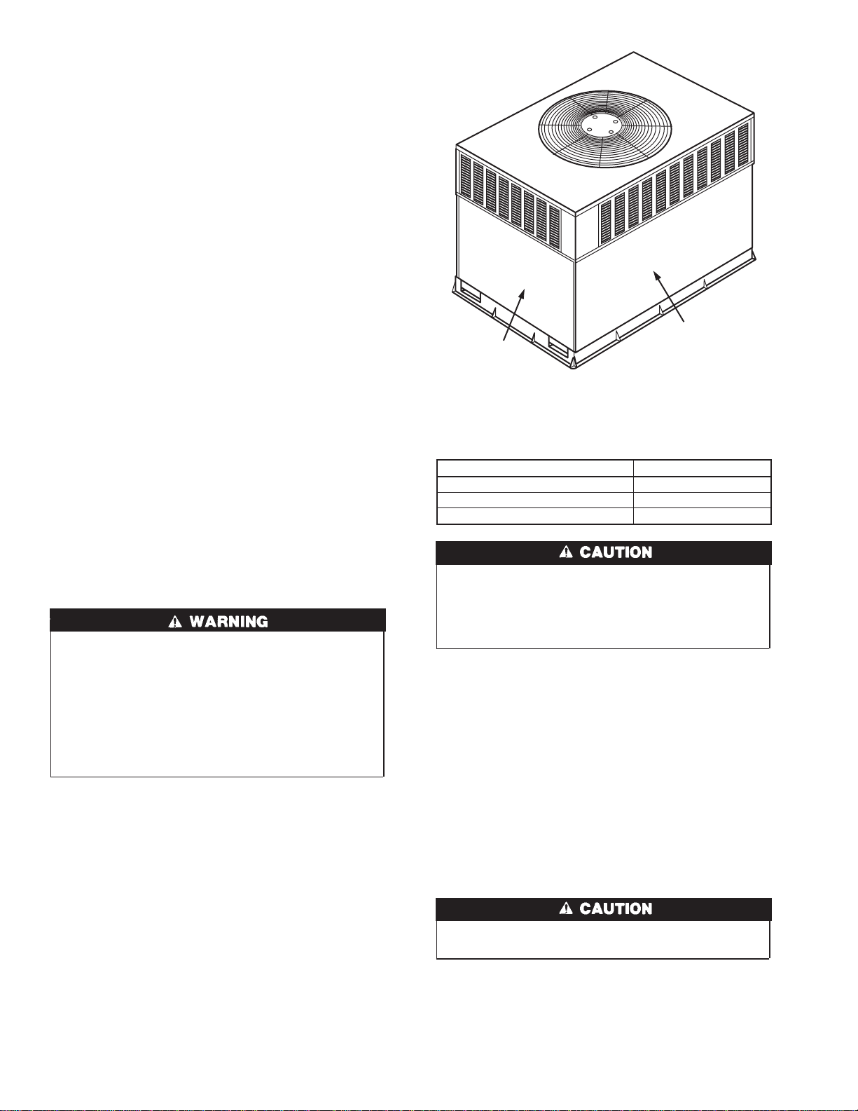
Fig. 2—Filter Access Panel—Vertical Supply
Shown
ACCESS PANEL
FILTER ACCESS
PANEL*
*For accessory filter rack.
Table 1 — Indoor-Air Filter Data
UNIT SIZE FILTER SIZE
50JZ024-030 20x20x1
50JZ036 20x24x1
50JZ042-060 24x30x1
2
REFRIGERANT CIRCUIT — The refrigerant circuit is difficult
to check for leaks without the proper equipment; therefore, if
inadequate cooling is suspected, contact your local dealer for
service.
System under pressure. Relieve pressure and recover all
refrigerant before system repair or final unit disposal to avoid
serious injury or death. Use all service ports and open all
flow-control devices, including solenoid valves.
UNIT PANELS — After performing any maintenance or service
on the unit, be sure all panels are fastened securely in place to
prevent rain from entering unit cabinet and to prevent disruption of
the correct unit airflow pattern.
REGULAR DEALER MAINTENANCE
In addition to the type of routine maintenance you might be willing
to perform, your unit should be inspected regularly by a properly
trained service technician. An inspection (preferably each year, but
at least every other year) should include the following:
1. Inspection and, if required, cleaning of the outdoor and indoor
coils.
2. Inspection and, if required, cleaning of the indoor coil drain
pan.
3. Inspection and cleaning of blower wheel housing and motor.
4. Inspection of all supply-air and return-air ducts for leaks,
obstructions, and insulation integrity. Any problems found
should be resolved at this time.
5. Inspection of the unit base to ensure that no cracks, gaps, etc.,
exist which may cause a hazardous condition.
6. Inspection of the unit casing for signs of deterioration.
7. Inspection of all electrical wiring and components to assure
proper connection.
8. Inspection for leaks in the refrigerant circuit. Pressure-check
to determine appropriate refrigerant charge.
9. Inspection of compressor oil level by service person to ensure
proper oil level is maintained in the compressor when it is
installed and running.
10. Operational check of the unit to determine working condi-
tions. Repair or adjustment should be made at this time.
Your servicing dealer may offer an economical service contract
that covers seasonal inspections. Ask for further details.
Complete service instructions can be found in the unit Installation,
Start-Up and Service Instructions.
WARRANTY CERTIFICATE
Unit 50JZ has a limited warranty. Be sure to read the warranty
carefully to determine the coverage for your unit.
BEFORE YOU CALL FOR SERVICE, CHECK FOR SEV-
ERAL EASILY-SOLVED PROBLEMS
If insufficient heating or cooling is suspected:
( ) Check for sufficient airflow. Check the air filter for dirt. Check
for blocked return-air or supply-air grilles. Be sure they are open
and unobstructed. If these checks do not reveal the cause, call your
servicing dealer.
If your unit is not operating at all, check the following list for easy
solutions:
( ) Check to be sure that your thermostat temperature selector is set
below the indoor temperature during the cooling season or above
the indoor temperature during heating season. Be sure the SYS-
TEM switch or MODE control is in the COOL or HEAT position
and not in the OFF position.
( ) If your unit still fails to operate, call your servicing dealer for
troubleshooting and repairs. Specify the model and serial numbers
of your unit. (Record them in this manual in the space provided.)
If the dealer knows exactly which unit you have, he may be able
to offer suggestions over the phone, or save valuable time through
knowledgeable preparation for the service call.
IN CASE OF TROUBLE
If after performing the above and unit performance is still
unsatisfactory, shut off the unit and call your dealer.
Dealer’s Name..................................................................................
Telephone .........................................................................................
Unit Model .......................................................................................
Unit Serial Number..........................................................................
3
Copyright 2000 CARRIER Corp. • 7310 W. Morris St. • Indianapolis, IN 46231 om5029
Manufacturer reserves the right to discontinue, or change at any time, specifications or designs without notice and without incurring obligations.
Book 1 4
Tab 5a 5a PC 101 Catalog No. 565-070 Printed in U.S.A. Form OM50-29 Pg 4 8-00 Replaces: New