manuals.online logo
Brands
  1. Home
  2. •
  3. Brands
  4. •
  5. Carrier
  6. •
  7. Heat Pump
  8. •
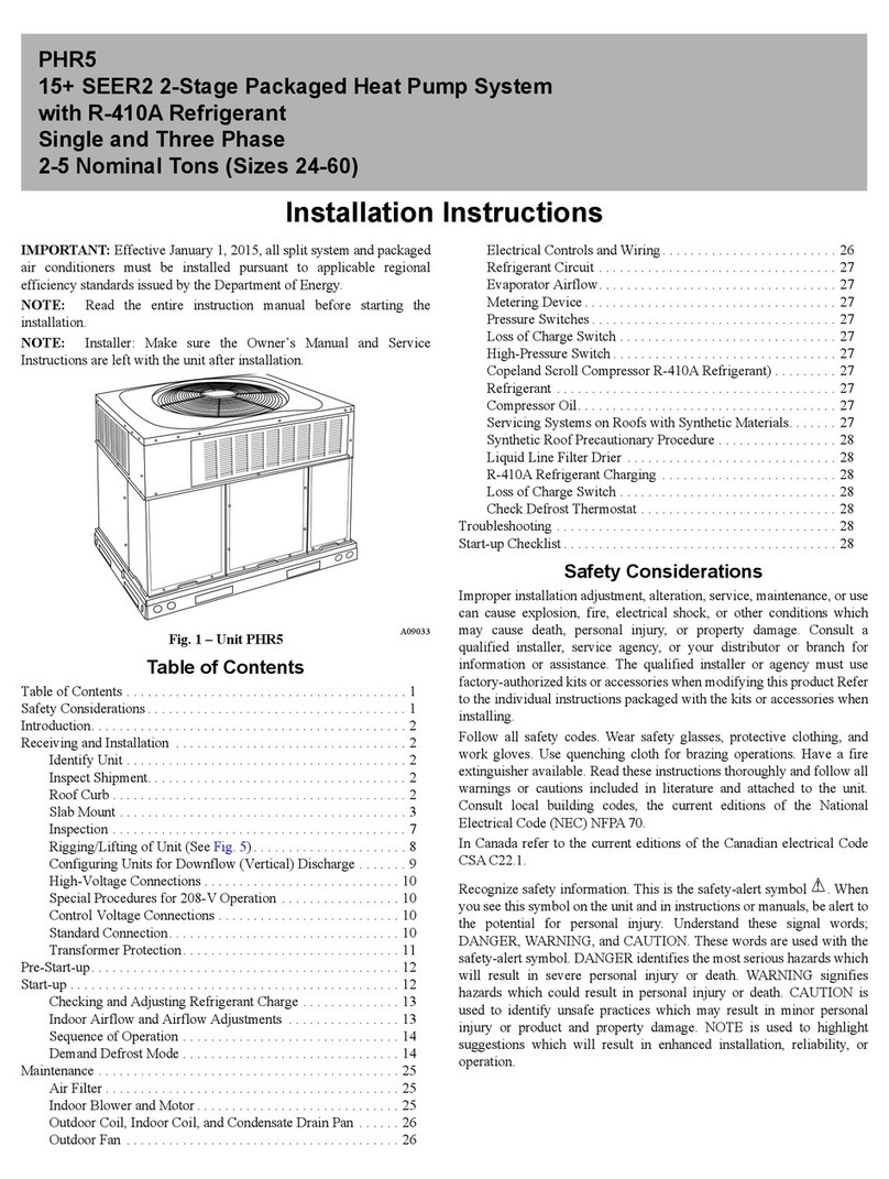
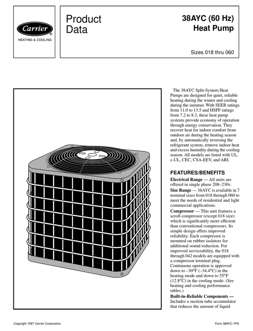
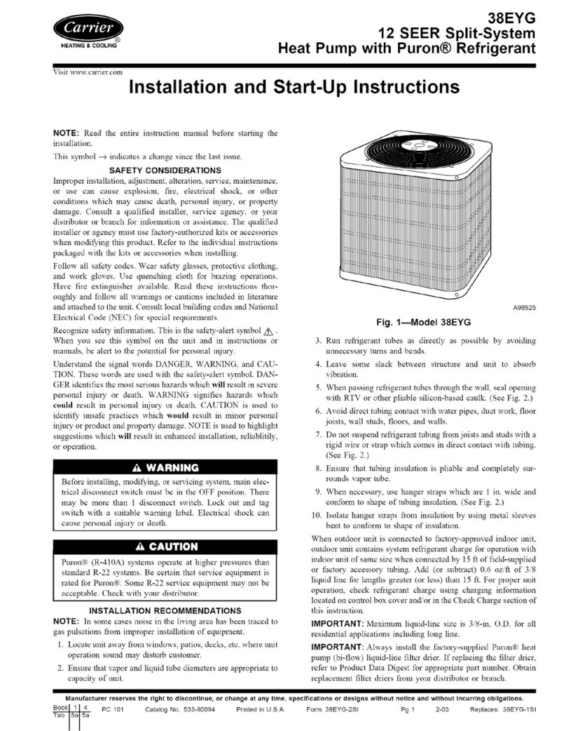
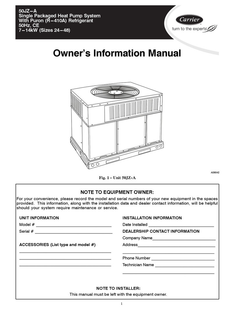
  9. Carrier XCT 7 40VC009-048F-7G-QEE Installation instructions

Carrier XCT 7 40VC009-048F-7G-QEE Installation instructions

Installation and Owner’s Manual
Flex Ceiling Floor
MODEL NAME
40VC009~048F-7G-QEE
Edition: 2020-05
No. 0150543404
Gontents
Xhe indoor unit3 suspended to ceiling or
standing on floor3 renders considerable
operating ease and flexibility5
[ith its ultra4thin design3 dazzling exterior
and space economy3 the indoor unit fits in
well with indoor scenarios5
Foasting superb power and fast temperature
tuning3 the indoor unit delivers undeniable
comforts and pleasures whenever you feel
li e wanting the same5
Lighly efficient silencing technology greatly
reduces operating noises and delivers natural
comforts5
Mn case of sudden blac out during operation3
the indoor unit3 with its Flac out Vetrieval
function preset3 is capable of retrieving its
operating status prior to the blac out when
power supply is restored5
Mntegrated Gontrol is available with the indoor
unit /through integrated controller05
Qulti4connected unit series features ~uniform
control mode*3 i5e53 all indoor units are
restricted to run on heating or cooling mode
at the same time5
Jor the protection of compressor3 the air
conditioning unit shall be powered for over
89 hours5
Mf the supply cord is damaged3 it must be
replaced by the manufacturer3 its service agent
or similarly qualified persons in order to avoid
a hazard5
Xhis appliance is not intended for use by
persons /including children0 with reduced
physical3 sensory or mental capabilities3 or
lac of experience and nowledge3 unless they
have been given supervision or instruction
concerning use of the appliance by a person
responsible for their safety5
Ghildren should be supervised to ensure that
they do not play with the appliance5
Xhis appliance can be used by children aged
from ? years and above and persons with
reduced physical3 sensory or mental
capabilities or lac of experience and
nowledge if they have been given supervision
or instruction concerning use of the appliance
in a safe way and understand the hazards
involved5 Ghildren shall not play with the
appliance5 Gleaning and user maintenance
shall not be made by children without
supervision5
Xhe appliances are not intended to be
operated by means of an external timer or
separate remote4control system5
Oeep the appliance and its cord out of reach
of children less than ? years5
35EB=B;
Yser Qanual
Tarts and Junctions
8
Wafety
:
?
Jault Ghec up
@
Mnstallation Trocedures
8=
Ilectrical [iring
99
Xest Vun . Jault Gode
>
Qaintenance
cooling
dry
heating
indoor
outdoor
indoor
outdoor
max5
min5
max5
min5
max5
min5
max5
min5
HFA :9
[FA 8<
HFA 8?
HFA ;:
HFA 4<
HFA 9>
HFA 8<
HFA 98
HFA 48<
[FA 9:
[FA 8;
[FA 9=
-D9E5G=B; /5B;9 C: x=E yCB8=G=CB9E
9;
Qove and scrap the air conditioning
Qodel ;7ZG77@{79;J4>K4UII
dATKUURT =QJNIHVRT
e7NT =QOKV
f@WVOKV <WNJK AOHVK
g@WVOKV ;OHS
Qodel ;7ZG79?{7;?J4>K4UII
^8RQVTRO AHQKO
_: KTLKQIZ @SKTHVNRQ DYNVIM
`CK RVK 8RQVTRO DNLQHO GNQJRY CKIKNXKT
aARYKT =QJNIHVRT
b@SKTHVNRQ =QJNIHVRT
cEN NQL =QJNIHVRT
8
Tarts and Junctions
Y
^
WV_W
Z
\
]
Y
Tower Wupply
Speration
Ximing
Tressor
Imergency Wwitch
X
[
Jront Tanel
Tower Wupply Speration Ximing Tressor
Imergency Wwitch
Eir Mnlet
TowerWupply Speration Ximing Tressor
ImergencyWwitch
~B8CCE 2B=G
3=B8 z=E97G=CB /9;H@5G=CB
Euto Eirflow
Tress the [ind Hirection button3 outlet guide
plate changes posture as shown below5
M
N
P
Q
qpo nm
LIEXA
Qodel ;7ZG77@{79;J4>K4UII
Qodel ;7ZG79?{7;?J4>K4UII
9
Tarts and Junctions
|=K=B; -HG@9G z=E97G=CB
Hecide upon a proper angle when guide plates move in auto airflow mode and press [ind Hirection
button to fix wind direction5
Ypper6lower flaps commanding airflow directions shall be positioned as follow when fixing wind
directionsA
Ypward in cooling and drying mode
Hownward in heating mode
Qa e sure that outlet plates or flaps are adjusted only and always through the [ind Hirection
button on remote controlB manual adjusting may cause malfunction5
Sutlet guide plates constantly positioned downwards are prohibited when cooling and drying
modes are activated as vapor close to outlet grille may condense and resultant water may drip
down from the unit5
Tlease pay close attention to temperature regulation values when operating the unit in places
where infants3 children3 old people and patients are to be found5
Eir Kuide Tlate
Tositioning Wwing Vange
m
n
o
p
q
mo
mo
np
oq
mq/Ell Govered0
mno pq
GSSP6HV]6JERA
Euto Eirflow
Tress Yp6Hown Eirflow button3 outlet guide
plate changes posture as follows
q
m
n
o
p
Ypper6Power Kuide Tlates Wwing VangeA
Vecommended angles at which swinging guide
plate stops
Gooling and Hrying
Eir Helivery along
Lorizontal Hirection
Hownward Eir Helivery
Leating
:
Wafety
Mf the air conditioner is transferred to a new user3 this manual shall be transferred to the user3
together with the conditioner5
Fefore installation3 be sure to read Wafety Gonsiderations in this manual for proper installation5
Xhe safety considerations stated below is divided into ~ [arning*and ~ Ettention*5 Xhe
matters on severe accidents caused from wrong installation3 which is li ely to lead to death or
serious injury3 are listed in ~ [arning*5 Lowever3 the matters listed in ~ Ettention*are also
li ely cause the severe accidents5 Mn general3 both of them are the important items related to
the security3 which should be strictly abided by5
Efter the installation3 perform test run to ma e sure everything is in normal conditions3 and then
operate and maintain the air conditioner in accordance with the Yser Qanual5 Xhe Yser Qanual
should be delivered to the user for proper eeping5
T
[arning
T T
T T
Tlease as the special maintenance station for installation and repair5 [ater lea age3 electric
shoc s or fire accidents might be caused from improper installation if you conduct the installation
by your own5
Xhe installation should be conducted properly according to this manual5 [ater lea age3 electric
shoc s or fire accidents might be caused from improper installation5
Tlease ma e sure to install the air conditioner on the place where can bear the weight of the
air conditioner5 Xhe air conditioner can}t be installed on the grids such as the non4special metal
burglar4proof net5 Xhe place with insufficient support strength might cause the dropdown of the
machine3 which may lead to personal injuries5
Xhe installation should be ensured against typhoons and earthqua es3 etc5 Xhe installation
unconformable to the requirements will lead to accidents due to the turnover of the machine5
Wpecific cables should be used for reliable connections of the wirings5 Tlease fix the terminal
connections reliably to avoid the outside force applied on the cables from being impressed on
the cables5 Mmproper connections and fixings might lead to such accidents as heating or fire
accidents5
Gorrect shapes of wirings should be ept while the embossed shape is not allowed5 Xhe wirings
should be reliably connected to avoid the cover and the plate of the electrical cabinet lipping
the wiring5 Mmproper installation might cause such accidents as heating or fire accidents5
[hile placing or reinstalling the air conditioner3 except the specific refrigerant /V;87E03 don}t
let the air go into the refrigeration cycle system5 Xhe air in the refrigeration cycle system might
lead to the crac ing or personal injuries due to abnormal high pressure of the refrigeration cycle
system5
Huring installation3 please use the accompanied spare parts or specific parts5 Mf not3 water
lea age3 electric shoc s3 fire accidents or refrigerant lea age might be caused5
Hon}t drain the water from the drainpipe to the waterspout where may exist harmful gases such
as sulfureted gas to avoid the harmful gases entering into the room5
Huring installation3 if refrigerant lea age occurs3 ventilation measures should be ta en3 for the
refrigerant gas might generate harmful gases upon contacting the flame5
Efter installation3 chec if any refrigerant lea age exists5 Mf the refrigerant gas lea s in the room3
such things as air blowing heaters and stoves3 etc5 may generate harmful gases5
;
Wafety
Hon}t install the air conditioner at the places where the flammable gases may lea 5 Mn case the
gas lea age occurs around the machine3 such accidents as fire disasters may be caused5
Xhe drainpipe should be properly mounted according to this manual as to ensure the smooth
drainage5 Mn addition3 heat preservation should be ta en to avoid condensation5 Mmproper drainpipe
mounting might cause water lea age3 which will get the articles at home wet5
Xhe refrigerant gas pipe and liquid pipe should be heat insulated to preserve heat5 Jor inappropriate
heat insulation3 the water caused from the condensation will drop to get the article at home wet5
T
Ettention
Xhe air conditioner should be effectively grounded5 Ilectric shoc s may occur if the air conditioner
is ungrounded or inappropriately grounded5 Xhe wire for earthing shouldn}t be connected to the
connections on the gas pipe3 water pipe3 lightning rod or telephone5
Xhe brea er for electricity lea age should be mounted5 Mf not3 accidents such as electric shoc s
may happen5
Xhe installed air conditioner should be chec ed for electricity lea age by being powered5
Mf the ambient humidity bigger than ?7-3 when the water discharge hole be bloc ed or the filter
becomes dirty3 or airflow speed change3 there maybe leads to condensing water drop down3
and at the same time there maybe some drops of water spit out5
<
Wafety
Xhe machine operation must be controlled
by the control5
LintsA
Es air conditioners absorb heat from the
environment and release it to the room3
heating effects will be influenced by the
temperature in and out of the room5
HefrostingA
Huring heating running3 the air conditioner
would defrost automatically if there is frost
on heat exchanger of outdoor units5
Ho not rotate fans of both indoor units and
outdoor units during defrosting5
Efter finishing defrosting3 the air conditioner
will resume running automatically5
Vegulating [ind HirectionA
Mt is recommended not to ma e the wind
deflector downwards for a long time to avoid
condensation at air outlet port during
refrigerating or dehumidifying5
[ater dropping might appear at the air
outlet port in refrigerating or dehumidifying
mode5
Evoid cold wind from blowing out5
Huring heating running3 the fan of indoor
units will not rotate immediately as to
prevent cold wind from blowing out5
wait for a moment
`
Ghanging [ind WpeedsA
Mn the state of refrigerating3 with automatic
blowing mode3 the wind speed automatically
decreases when the room temperature
approaches the setting5
Mn the state of heating3 when the room
temperature reaches the setting temperature
the compressor stops wor ing and the fan
turns to low wind or stops5 [ind speed
changes automatically in the dehumidifying
mode5
Glean the filter regularly5
Gooling or heating performance will be
degraded if the filter is bloc ed3 resulting
in large power consumption3 failure3 and
water dripping
at freezing5
Hon}t touch the outlet while the flap is
moving5 Hon}t put anything in the grid in
case danger may occur5
Mtems with this warning sign concerning the product}s safety and the personal
security must be performed strictly5
Mtems with this forbidding sign refer to absolutely forbidden behaviors5 Mf not3 they
may cause machine damage or endanger operator}s personal safety5
=
Wafety
TEttention
Tay attention to the
aeration condition
to avoid anoxic
symptom5
Mt is not allowed to put any heating
apparatus under the indoor units3 for the
heat may cause distortion of the units5
Jlammable apparatus should not be placed
in the place where the air conditioner wind
could reach directly3 or incomplete burning
of the apparatus
may be caused5
:4minute protection
Xo protect the unit3 compressor can be
actuated with at least :4minute delay after
stopping5
,CG=79F 8HE=B; -D9E5G=CB
Glose the window to avoid outdoor air
getting in5
Gurtains or window
shutters can be put
down to avoid the
sunshine5
Ho not put flammable spray close to the air
conditioner5
Hon}t inject flammable spray towards the
air conditioner3 which may
cause fire5
Wtopping fan rotation
Xhe unit which stops operating will actuate
the fan for a 94? min swing every :74=7
minutes for protecting the unit while other
indoor unit are in the operating state5
Tower should be cut off when the air
conditioner is left unused for a long period5
Tower will be consumed if the air
conditioner is not powered off5 Xhe power
switch of the outdoor unit switch should be
powered on 89 hours in advance before
operation to protect the unit after a long
period of storage5
Hefrosting during heating
Xo improve the heating effect3 the outdoor
unit will perform defrosting automatically
when frost appears on the outdoor unit
during heating /approximately 9487 min05
Huring defrosting3 the fan of the indoor unit
runs at a low speed or stops while that of
the outdoor unit stops running5
Ho not use water heater or li e next to the
indoor unit and the wired controller5
[ater6power lea age or short circuit may
happen if the steam generating apparatus
is wor ing next to machine5
Yse the fuse with proper capacity5
Qetal wires and copper wires3 etc53
may cause fire or other faults5
Mt cannot be used for the preservation of
food3 living creature3 precise instrument
and artwor s3 etc3 otherwise damage
may occur5
Tlants and animals should not be put to
the place where wind of the air conditioner
blows directly3 otherwise damage to
them may be caused5
Ghec the mount table
of the air conditioner for damage for a long
period of operation5
Mf placed on the damaged table3 the
unit may drop down causing damage5
Xhis appliance is not intended for use by
persons /including children0 with
reducedphysical3 sensory or mental
capabilities3 or lac of experience and
nowledge3 unless they have been given
supervision or instruction concerning use
of the appliance by a person responsible
for their safety5
Gleaning the unit with water may cause
electric shoc 5
Ho not touch the switch with the wet
hand to avoid power shoc 5
Wtop running and switch off the manual
power switch when cleaning the
unit5
Huring the operation of the control unit3
don}t switch off the manual power switch
and the controller can be used5 Tlease do
not press the liquid crystal zone of
controller to prevent damage
>
Qaintenance
l
Snly when the air cleaner is switched off and disconnected to the power supply can it be cleaned3
or electric shoc and injury may appear5
Qaintenance before and after Sperating Weason
Fefore Sperating WeasonA
85 Tlease ma e the following chec up5 Mf abnormal condition occurs3 consult the after4service
personnel5
Xhere is no bloc age in inlet port and outlet port of outdoor and indoor units5
Xhe ground line and the wiring are in the proper state
95 Efter cleaning3 the air cleaner must be mounted5
:5 Wwitch on to the power5
Efter Sperating WeasonA
85 Mn sunny days3 blowing operation can be performed for half a day to ma e the inside of
machine dry5
95 Ilectrical power should be cut down to economize electricity3 or the machine will still
consume power5Eir cleaner and shell must be mounted after cleaning5
Gleaning [ind HeflectorA
Ho not wipe the wind deflector with water forcibly to avoid falling off5
Gleaning the air outlet port and the shellA
Hon}t use gasoline3 benzene3 diluents3 polishing powder or liquid insecticide to clean them5
Ho not clean them with hot water of above <7]to avoid fading or distorting5
Ettention
[ipe them with soft dry cloth5
[ater or neutral dry cleanser is recommended if the dust cannot be removed5
Xhe [ind Heflector can be dismantled to clean /as below05
Tull the air screen forward to the front side
of the unit to remove it5
Glean up air screens according to their
different types5 Jor more information3
please ma e contact with
after service staff5
Gleaning Eir GleanerA
Hon}t rinse the air cleaner with hot water of above [V]to avoid fading and distorting5
Hon}t put the air cleaner on the fire to dry to avoid catching fire5
Ettention
/F0 Glean it with soft bush in mild detergent
if there is too much dust on it
/G0Xhrow off the water and airing it
in the cool dry condition5
[ipe dust with water or dust collector5
/E0 [ipe dust with dust collector5
?
[ater flow sound
Grac ing sound
Xerrible smell in
outlet air
Jlashing operating
indicator
Ewaiting indication
Wound in
shutdown indoor
unit or white
steam or cold air
Glic ing sound
when switching the
air condition on
Ell these are not problems
Wtart or stop wor ing
automatically
Jailure to wor
Fad cooling .
heating effects
Tlease ma e another chec 5
[hen other abnormal conditions occur5
Ynder the following circumstances3 immediately stop the operation3 disconnect the manual supply
switch and contact the after4service personnel5
[hen buttons are inflexible actuatedB
[hen it cannot still be operated after removing the operation of protective unitB
[hen fuse and brea er have been burnt over and overB
[hen there are foreign objects and water in the refrigeratorB
Tlease chec the following when consigning repair serviceA
Wymptoms Veasons
[ater flow sound can be heard when starting operation3 during
operation or immediately after stopping operation5 [hen it starts
to wor for 94: minutes3 the sound may become louder3 which is
the flowing sound of refrigerant or the draining sound of condensed
water5
Huring operation3 the air conditioner may ma e the crac ing
sound3 which is caused from the temperature changes or the
slight dilation of heat exchanger5
Xhe terrible smell3 caused from walls3 carpet3 furniture3 clothing3
cigarette and cosmetics3 attaches on the conditioner5
[hen switching it on again after power failure3 turn on the manual
power switch and the operating indicator flashes5
Mt displays the awaiting indication as it fails to perform refrigerating
operation while other indoor units are in heating operation5 [hen
the operator set it to the refrigerating or heating mode and the
operation is opposite to the setting3 it displays the awaiting indication5
Xo prevent oil and refrigerant from bloc ing the shutdown indoor
units3 refrigerant flows in the short time and ma e the sounds
of refrigerant flowing5 Stherwise3 when other indoor units performs
heating operation3 white steam may occurB during refrigerating
operation3 cold air may appear5
[hen the conditioner is powered on3 the sound is made due
to the resetting of the expansion valve5
Ghec if it is in the state of Ximer4SR and Ximer4SJJ5
Ghec if there is a power failure5
Ghec if the manual power switch is turned off5
Ghec if the supply fuse and brea er are disconnected5
Ghec if the protective unit is wor ing5
Ghec if refrigerating and heating functions are selected
simultaneously with the awaiting indication on line control5
Ghec if air inta e port and air outlet port of outdoor units are
bloc ed5
Ghec if the door and windows are open5
Ghec if the filtering screen of air cleaner is bloc ed with sludge
or dust5
Ghec if the setting of wind quantity is at low wind5
Ghec if the setting of operation is at the Jan Speration state5
Ghec if the temperature setting is proper5
Jault Ghec up
@
Mnstallation Trocedures
Xhis manual does not cover all user casesB please contact Garrier mar eting centers in local
places to propose new requirements and clear new doubts and problems5
85 Xhe distance from air outlet to floor surface shall not exceed 95>m5
95 Qa e sure that outlet airflow covers the whole room areaB and arrange connecting tubes3 wires
and drain pipes to proper outdoor positions5
:5 Qa e sure that ceiling structures are capable of bearing unit weight5
;5 Gonnecting tubes3 drain pipes and connecting wires can be put across walls to connect indoor
unit and outdoor unit5
<5 Gonnecting tubes and drain pipes between indoor and outdoor units shall be shorter for better5
=5 Tlease refer to outdoor installation manual when refrigerant charging volume adjusting is
necessary5
>5 Noint flanges shall be prepared by users5
?5 Zaluables /e5g53 XZ sets3 instruments3 equipments3 artwor s3 pianos3 wireless devices0 shall
not be placed below the indoor unit lest condensed water drips upon the same5
~BFG5@@=B; ~B8CCE 2B=G
>7mm
Mndoor Wide
[all Lole
[all Xhic ness
Jigure 8 /[all Lole in Wection0
Sutdoor Wide
qp zE=@@=B; 35@@ }C@9F
Mnstalling and Jixing
Hrill a wall hole /dia5>7mm3 see figure 803 slightly tilted
downwards on the outsideB fix guard ring to finalize
before sealing the wall hole with gesso or putty5
Tlaces /in coastal areas0 where salinity is highB where sulfurized gases are usual /areas where
springs flourish and copper tube and braze easily get corroded0B where oils /machinery oils0
and steam are usualB where organic solvents are put to useB where machines radiating high
frequency electromagnetic waves exist /which cause control system malfunctions0B where
contact with humid air near windows and doors is pervasive /ma ing for easy condensation0
andB where special sprayers are put to frequent use5
l
z97=89 HDCB D@579F GC =BFG5@@ G<9 =B8CCE HB=GwD@579F J<9E9 9I9B 7=E7H@5G=CB C: 7CC@
5B8 J5EA 5=E 75B 69 89@=I9E98 F<5@@ 69 F9@97G98w5B8 D@579F 69@CJ F<5@@ 69 5IC=898v
Jigure 9 Qodel ;7ZG77@{79;J4>K4UII Jigure : Qodel ;7ZG79?{7;?J4>K4UII
TowerWupply Speration Ximing Tressor
ImergencyWwitch
rp .E9D5E5G=CB DE=CE GC ~BFG5@@=B; ~B8CCE 2B=G
Spen inlet grille according to figure 9 and figure :5
Wtandard installation tools are recommended according to installation requirements5
Jor information about standard model series accessories3 see pac ing listB other necessary parts
to be installed shall be prepared by users as required by installation service networ stations5
87
Mnstallation Trocedures
Hownwards
Fac wards
_Eccording to figure on the right3 choose a certain direction to
lead out drain pipeB drain holes are available on both right and
left sidesB practical conditions shall be considered5 Efter deciding
upon the directions to lead out pipelines3 wires and drain pipes3
drill wall holes according to required drilling processes5
`Mnstall wall mount rac according to figure below5
Mn case of model 9948;73 fix drain pipes to drain holes on left and right sides /as shown in figure
; and figure <05
Mnstall as follows /see figure below0A
Tlug drain pipe in water pan in the first place3 as shown by figure3 then3 bind the two tight together
and tie up junction area with heat insulant5
[ater Tan [ater Tan
Hrain Tipe Hrain Tipe
Fond
Leat Mnsulant
aMnstalling Hrain Tipe
sp|@CCE 1LD9 ~BFG5@@5G=CB
^Jix four rubber feet to the bottom of the unit with ;\8= bolts
and 89 spacers /applicable to floor type units only05
Jigure < Qodel ;7ZG79?{7;?J4>K4UII
Vight Wide Hrain LolePeft Wide Hrain Lole
Vight Wide
Hrain Lole
Peft Wide
Hrain Lole
Jigure ; Qodel ;7ZG77@{79;J4>K4UII
Geiling Qount Vac
Idge
13
i
[all Lole >7mm
=<<mm
@@7mm
<77mm 9;<mm
=<mm
89<mm 877mm
=<mm
<:7mm
;>:mm
Qodel ;7ZG77@{79;J4>K4UII
88
Mnstallation Trocedures
Ettention to distance from the unit to household usables or obstacles /as shown with figure05
Peft
Vight
Sver :7cmSver :7cm
GEYXMSRA drain pipe leading4out direction shown with figure below5
tpy9=@=B; ~BFG5@@5G=CB
;7ZG77@{79;J4>K4UII
;7ZG79?{7;?J4>K4UII
Sver :7cm
ab
Qodel
Sver ?7cm
Sver :7cm
Sver 8<7cm
Sver 9cm
c
Sver 87cm
Geiling Mnstallation
^Yse 87 hanger bolts3 prepared on the site5
Tlease refer to figure on the right when installing5
F/Langer Folt Glearance0
Langer Folt
Pess than ;7mm
=<< 8><977
G/mm0 H/mm0 I/mm0
@77
E/mm0 F/mm0
@@7
Qodel
;7ZG77@{79;J4>K4UII
;7ZG77@{79;J4>K4UII
[rong
[rong
Hrain Tipe
Gorrect
Hrain pipe shall be positioned
high on the inside and low
on the outside5
Peft
Vight
Geiling
a
c
b
Folt Lole for Mnstallation
/Langer Folt Glearance0
;489x9>Lole
F
E
c
b
a
Langer Folt Qounting Tosition
/Langer Folt Glearance0
89
Mnstallation Trocedures
Langer Folt Trotrudes :74<7mm
Geiling Spening WizeA 8<:7mm
;7mm ;7mm
Geiling
Geiling Spening WizeA =;7mm
Geiling
8<mm
Mnstallation Wpace Himension
Langer Folt Glearance 8<:7mm
:7mm :7mm
87mm
8<<mm
:77mm
Yse Q87 hanger bolt /prepared on the site0 featuring =7mm hole depth3 clearance fixed according
to size proposed in the air conditioner external viewB install according to different building structure
specifications to guard against safety faultsB and leveling instruments shall be available to ensure
balanced installation5
;7ZG79?{7;?J4>K4UII
_Mnstalling Langer Folt
`Tlease use hexagon bolts when installing
/ 870
Hotted line suggests
position behind the unitB
please cut off before use5
Mndoor Ynit
Folt
?48:mm
Tosition of Langer Folt
F/mm0 /internal hanging0
9
8:
Mnstallation Trocedures
bMnstalling Heco Tlate and Mnlet Krille /after pipeline laying and electric wiring are done05
Langer Folt
Folt Wleeve
Lexagon Folt
Qounting Vac
jZVee
Jlat Wpacer
Houble Rut
Ynit
dWV
Geiling
Langer bolt is ;7mm below ceiling5
Folt
Qounting Vac
Eccording to requirements on the site3
drain pipes shall be prepared by users
on their own resources and ma e sure
that these are connected to drain pipes
previously available with the unit /ma e
sure that measures are ta en to guard
against water lea age in junction areas0B
heat preservation shall be available with
certain indoor drain pipes through using
heat insulant to prevent condensation5
GEYXMSRA drain pipe shall be positioned
high inside and low outside5
/[all0
/Geiling0
aEir Gonditioner Mnstallation Hiagram
_Mnstalling Wtatus of Qounting Vac ^Langer Ghain Loo
`Mnstalling Eir GonditioneraHrain Tipe Peading4out Hirection
Wcrew tight hexagon bolt to fix air
conditioner
Mnsert hexagon bolt into slot
Peveling is forbidden after air conditioner
is installedB please ma e adjustment
according to diagram indication5
8;
Mnstallation Trocedures
Tiping
Qaterial
Leat Mnsulating
Qaterial
Lard TZG tube ZT:85<mm
/inner bore0
Zesicant polythene
thic nessA over >mm
heat insulating
material
hose hose clamp
attached heat
insulating material horniness pvc pipe
Huring the test run3 chec the condition of water
drainage and ma e sure that there is no lea age on
the connection of piping3 which should also be
performed during the winter5
Gonfirming water drainage
Jor normal drainage3 the water drainage piping should be connected according to the
installation manual5 Leat insulation should be performed to avoid condensation5 Mmproper
pipe connection may cause water going into the machine5
Ettention
r
Lose
Xhe drainage hose is made of 8@57<mm /:6;*0 TZG tube3 which can adjust the eccentricity and
the angle of the hard TZG tube5
Wtretch the hose directly to ma e connections as to avoid distortion5 Xhe soft end of the hose
should be positioned with a clamp5
Xhe hose should be used in the horizon direction5
Leat Mnsulating XreatmentA
[rap the connection between the clamp and the root segment of the indoor unit without any
gap with heat insulating materials as shown in the drawing
Tiping Qaterials . Leat Mnsulating Qaterials
Es to prevent condensation3 heat
insulating treatment should be
performed5 Xhe heat insulating treatment
for piping should be done respectively5
VequirementsA
85<m{9m support
heat
insulating
material
down gradient of over 86877 W4shape elbow ZT:7
max5 height /about 87cm0
down gradient
of over 86877
Leat insulating treatment should be made for the water drainpipes of the indoor units5
Leat preservation should be made for the connection with the indoor units5 Mmproper heat
preservation may cause condensing5
Xhe drainpipe should be designed with a down gradient of 868775 Xhe midway of the elbow
shouldn}t be made in W shape5 Sr abnormal noise may be caused5
Xhe lateral length of the drainpipe should be ept within 97m5 Ynder the condition of long pipe3
a support should be provided every 85<9{9m to avoid unevenness5
Xhe central piping can be connected according the following figure5
Hon}t apply external force to the connection of drainpipes5
8<
Mnstallation Trocedures
=5:<
895>
@5<9
8<5??
Xubing Termissible Pength . Leight Hifference
Tlease refer to the attached manual of outdoor units5
Xubing Qaterials . Wpecifications
Vefrigerant Jilling Emount
Edd the refrigerant according to the installation instruction of outdoor unit5 Xhe addition of V;87E
refrigerant must be performed with a measure gage to ensure the specified amount while compressor
failure can be caused by filling too much or little refrigerant5
Gonnecting Trocedures of Vefrigerant Xubing
Troceed the flare tube connecting operation to connect all the refrigerant tubes5
Suter
Hiameter of
Xubing /mm0
Qounting
Xorque /R4m0 Mncrease mounting
Xorque /R4m0
=5:<
@5<9
895>
8<5??
885?/859 gf4m0
9;5</95< gf4m0
;@57/<57 gf4m0
>?5;/?57 gf4m0
8:5>/85; gf4m0
9@5;/:57 gf4m0
<:5@/<5< gf4m0
@?57/8757 gf4m0
Gutting and Inlarging
Gutting or enlarging pipes should be proceeded
by installation personnel according to the
operating criterion if the tube is too long or flare
opening is bro en5
Zacuumizing
Zacuumize from the stop valve of outdoor units
with vacuum pump5 Vefrigerant sealed in indoor
machine is not allowed to use for vacuumization5
Spen Ell Zalves
Spen all the valves of outdoor units5 ^RFA oil
balancing stop valve must be shut up completely
when connected one main unit5_
Ghec up for Eir Pea age
Ghec if there is any lea age at the connecting
part and bonnet with hydrophone or soapsuds5
Gonnecting
85 Gonnecting circular terminalsA
Gonnecting
circular terminalsA
Xhe connecting method of circular terminal is
shown in the Jig5 Xa e off the screw3 connect
it to the terminal tier after heading it through the
ring at the end of the lead and then tighten it5
9UGonnecting straight terminalsA
Xhe connection methods for the circular terminals
are shown as followsA loosen the screw before
putting the line terminal into the terminal tier3
tighten the screw and confirm it has been
clamped by pulling the line gently5
:UTressing connecting line
Efter connecting line is completed3 press the
connecting line with clips which should press on
the protective sleeve of the connecting line5
correct
pressing
terminal tier
pressing clip
wrong
pressing
Xubing Qaterial
Qodel
Xubing Wize
/mm0
Kas pipe
Piquid pipe
Thosphor deoxybronze seamless pipe /XT90 for air conditioner
wrench
2.F8./0[./5;-4<-B::
Hual wrenches must be used in the connection
of indoor unit tubing5
Qounting torque refers to the right table
2.F8..6;-4<-B::
=5:<
@5<9
2.F8.02[.25;-4<-B::
8=
35EB=B;
xGG9BG=CB
Wupply [iring Hrawing
Wub Ynit 8 of Sutdoor
Ynit
Wub Ynit 9 of Sutdoor
Ynit
WupplyA:R{3:?74;77Z3<76=7Lz WupplyA:R{3:?74;77Z3<76=7Lz WupplyA:R{3:?74;77Z3<76=7Lz
Mndoor Ynit 8
WupplyA8TL399749:7Z{3<76=7Lz WupplyA8TL399749:7Z{3<76=7Lz WupplyA8TL399749:7Z{3<76=7Lz
wall mounted type Mndoor Ynit 9 wall mounted type Mndoor Ynit 9
except wall mounted type
>/>0 >1 ? < >/>0 >1 ? < >/>0 >1 ? <
> ?
> ?/ 0
EG1 EG/ > ?/ 0
EG1 EG/
Frea er for
Ilectricity Pea age
Sverflow Frea er
Frea er for
Ilectricity Pea age
Sverflow Frea er
Frea er for
Ilectricity Pea age
Sverflow Frea er
Qain Ynit of Sutdoor
Ynit
Frea er for
Ilectricity Pea age
Frea er for
Ilectricity Pea age
Frea er for
Ilectricity Pea age
Sverflow Frea er Sverflow Frea er Sverflow Frea er
Ilectrical construction should be made with specific mains circuit by the qualified personnel according
to the installation instruction5 Ilectric shoc and fire may be caused if the capacity of power supply
is not sufficient5
Huring arranging the wiring layout3 specified cables should be used as the mains line3 which accords
with the local regulations on wiring5 Gonnecting and fastening should be performed reliably to avoid
the external force of cables from transmitting to the terminals5 Mmproper connection or fastness may
lead to burning or fire accidents5
Xhere must be the ground connection according to the criterion5 Ynreliable grounding may cause
electrical shoc s5 Ho not connect the grounding line to the gas pipe3 water pipe3 lightening rod and
telephone line5
Snly copper wire can be used5 Frea er for electric lea age should be provided3 or electric shoc
may occur5
Xhe wiring of the mains line is of ] type5 Xhe power plug P should be connected to the live wire
and plug R connected to null wire while should be connected to the ground wire5 Jor the type
with auxiliary electrically heating function3 the live wire and the null wire should not be misconnected3
or the surface of electrical heating body will be electrified5 Mf the power line is damaged3 replace it
by the professional personnel of the manufacturer or service center5
Xhe power line of indoor units should be arranged according to the installation instruction of indoor
units5
Xhe electrical wiring should be out of contact with the high4temperature sections of tubing as to avoid
melting the insulating layer of cables3 which may cause accidents5
Efter connected to the terminal tier3 the tubing should be curved into be a Y4type elbow and fastened
with the pressing clip5
Gontroller wiring and refrigerant tubing can be arranged and fixed together5
Xhe machine can}t be powered on before electrical operation5 Qaintenance should be done while
the power is shut down5
Weal the thread hole with heat insulating materials to avoid condensation5
Wignal line and power line are separately independent3 which can}t share one line5 ^RoteA the power
line3 signal line are provided by users5 Tarameters for power lines are shown as belowA :|/857485<0
mm9B parameters for signal lineA 9|/75><4859<0mm9/ shielded line0_
< butt lines /85<mm0 are equipped in the machine before delivery3 which are used in connection
between the valve box and the electrical system of the machine5 Xhe detailed connection is displayed
in the circuit diagram5
Mndoor units and outdoor units should be connected to the power source separately5 Mndoor units
must share one single electrical source3 but its capacity and specifications should be calculated5
Mndoor . outdoor units should be equipped with the power lea age brea er and the overflow brea er5
Ilectrical [iring
8>
Ilectrical [iring
TUEFG
TUEF G TUEFG TUE F G TUEF G TUEFG
EFG
EFG EFG EFG EFG
TUEF G TUEFG TUE F G TUEF G TUEFG
EFG
EFG EFG EFG EFG
EFG EFG
TUEF G TUEFG TUE F G TUEF G TUEFG
EFG EFG EFG EFG
EFG
TUE F G TUEF G TUEF G TUEF G
wired
controller
EFG
control wire for wired controller
with polarity
communication wire with polarity
outdoor 8 outdoor 9 outdoor :
TUEFGEFG
indoor 8 indoor 9 indoor : indoor ; indoor <
indoor = indoor > indoor ? indoor @ indoor 87
indoor 88 indoor 89 indoor 8: indoor 8; indoor 8<
indoor 8= indoor 8> indoor 8? indoor 8@ indoor 97
wired
controller
wired
controller
wired
controller
wired
controller
wired
controller
wired
controller
wired
controller
wired
controller
wired
controller wired
controller
wired
controller
wired
controller
wired
controller
wired
controller
wired
controller
wired
controller
Wignal [iring Hrawing
Sutdoor units are of parallel connection via three lines with polarity5 Xhe main unit3 central control and all
indoor units are of parallel connection via two lines without polarity5
Xhere are three connecting ways between line control and indoor unitsA
E5 Sne line control controls multiple units3 i5e5 948= indoor units3 as shown in the above figure3 /84< indoor
units05 Xhe indoor unit < is the line4controlled main unit and others are the ine4controlled sub units5 Xhe
remoter control and the main unit /directly connected to the indoor unit of line control0 are connected via
three lines with polarity5 Sther indoor units and the main unit are connected via two lines with polarity5W[78
on the main unit of line control is set to 7 while W[78 on other sub units of line control are set to 83 93 :
and so on in turn5 /Tlease refer to the code setting at page 8@0
F5 Sne line control controls one indoor unit3 as shown in the above figure/indoor unit =48@05 Xhe indoor unit
and the line control are connected via three lines with polarity5
G5 Xwo line controls control one indoor unit3 as shown in the figure /indoor unit 9705 Iither of the line controls
can be set to be the master line control while the other is set to be the auxiliary line control5 Xhe master
line control and indoor units3 and the master and auxiliary line controls are connected via three lines with
polarity5
[hen the indoor units are controlled by the remote control3 switch over the modes by Wwitching Qode of
Pine4Gontrolled Qain Ynit6 Pine4Gontrolled Wub Ynits6 Vemote4Gontrolled Xypes5 Xhe signal terminals needn}t
to be equipped with wires and connected to the line control5
lWwitching Qode of Pine4Gontrolled Qain Ynit6 Pine4Gontrolled Wub
Ynits6 Vemote4Gontrolled Xypes can be used for switching over l
8?
Ilectrical [iring
Xhe combination of multiple indoor units can be controlled by wired controller or remote controller5
RoteA;7ZG789{79;J4>K4UII models are set to remote4 controlled type before delivery
Wetting
Qode [ireless Vemote
Gontroller
Woc et6
Hip switch
W[784^8_^9_^:_^;_
GR98 Woc et Rull Gonnect to
remote receiver
Ell SJJ^7_^7_^7_^8_
Qaster Vemote [ired
Gontroller
8, Vemote [ired
Gontroller
Xerminal Floc
/Gontrol0
Rull
E3F3G connect with [ireless
Vemote Gontroller
F3G connect with [ireless
Vemote Gontroller E3F3G Rull
Ell SJJ
lXhe electrical power line and signal lines must be fastened tightly5
lIvery indoor unit must have the ground connection5
lXhe power line should be enlarged if it exceeds the permissible length5
lWhielded lays of all the indoor and outdoor units should be connected together3 with the shielded
lay at the side of signal lines of outdoor units grounded at one point5
lMt is not permissible if the whole length of signal line exceeds 8777m5
Xhe wiring for the power line of indoor unit3 the wiring between indoor and outdoor units as well
as the wiring between indoor unitsA
h87 9 97 97 97 E3:7 mE3758W or below
k87 and C8< :5< 9< :7 :7 E3:7 mE3758W or below
k8< and C99 <5< :7 ;7 ;7 E3:7 mE3758W or below
k99 and C9> 87 ;7 <7 <7 E3:7 mE3758W or below
Mtems
Xotal
Gurrent
of Mndoor
Ynits /E0
Gross
Wection
/mm90
Pength
/m0
Vated
Gurrent of
Sverflow
Frea er/E0
Vated Gurrent of Tower
Pea age Frea er /E0
Pea ing Gurrent/mE0
Sperating Teriod /W0
Gross Wectional
Erea of Wignal Pine
Sutdoor
4indoor
/mm90
Mndoor
4indoor
/mm90
9 coresi75><4957
mm9shielded line
Wignal [iring of [ired controller
Pength of Wignal Pine /m0
75><mm9\: core shielding line
[iring Himensions
lXhe shielding lay of the signal line must be grounded at one end5
lXhe total length of the signal line shall not be more than 9<7m5
j9<7

Other Carrier Heat Pump manuals

Carrier 38TH Instructions and recipes

Carrier

Carrier 38TH Instructions and recipes

Carrier 25HCB6 Performance Series User manual

Carrier

Carrier 25HCB6 Performance Series User manual

Carrier 38QB Dimensional drawing

Carrier

Carrier 38QB Dimensional drawing

Carrier COMFORT 50EZ-A Instruction Manual

Carrier

Carrier COMFORT 50EZ-A Instruction Manual

Carrier Aquazone 50PSW025 Dimensions and installation guide

Carrier

Carrier Aquazone 50PSW025 Dimensions and installation guide

Carrier Aquazone 50PCH PCV 007 Dimensions and installation guide

Carrier

Carrier Aquazone 50PCH PCV 007 Dimensions and installation guide

Carrier 09DK Series Dimensions and installation guide

Carrier

Carrier 09DK Series Dimensions and installation guide

Carrier 50HS018 Dimensions and installation guide

Carrier

Carrier 50HS018 Dimensions and installation guide

Carrier 50YX Operation manual

Carrier

Carrier 50YX Operation manual

Carrier 38YCA Series Operation manual

Carrier

Carrier 38YCA Series Operation manual

Carrier 42AM Series Manual

Carrier

Carrier 42AM Series Manual

Carrier 25HBR3 Operation manual

Carrier

Carrier 25HBR3 Operation manual

Carrier COMFORT 25HCS User manual

Carrier

Carrier COMFORT 25HCS User manual

Carrier 30AW User manual

Carrier

Carrier 30AW User manual

Carrier GT-PW (50YEW) User manual

Carrier

Carrier GT-PW (50YEW) User manual

Carrier RHW036-060 User manual

Carrier

Carrier RHW036-060 User manual

Carrier SOPRANO 50 User manual

Carrier

Carrier SOPRANO 50 User manual

Carrier 38AUQ 25 Series Dimensions and installation guide

Carrier

Carrier 38AUQ 25 Series Dimensions and installation guide

Carrier 38YH Operation manual

Carrier

Carrier 38YH Operation manual

Carrier 25hba User manual

Carrier

Carrier 25hba User manual

Carrier AquaForce 30XW-V Manual

Carrier

Carrier AquaForce 30XW-V Manual

Carrier 50HCQ12 User manual

Carrier

Carrier 50HCQ12 User manual

Carrier PHJ4 Instruction Manual

Carrier

Carrier PHJ4 Instruction Manual

Carrier 50ET Dimensions and installation guide

Carrier

Carrier 50ET Dimensions and installation guide

Popular Heat Pump manuals by other brands

Inter Water INTER HEAT SMART 115IS Installation instructions manual

Inter Water

Inter Water INTER HEAT SMART 115IS Installation instructions manual

Daikin EKHBRD011AAV1 installation manual

Daikin

Daikin EKHBRD011AAV1 installation manual

Viessmann BWC 201.B Connection instructions

Viessmann

Viessmann BWC 201.B Connection instructions

Rotex RRHQ006ADV3 installation manual

Rotex

Rotex RRHQ006ADV3 installation manual

Atlantic ALFEA Excellia mono Series manual

Atlantic

Atlantic ALFEA Excellia mono Series manual

Passion R06SPA User and service manual

Passion

Passion R06SPA User and service manual

AQUAHEAT ASC 70 user manual

AQUAHEAT

AQUAHEAT ASC 70 user manual

Acson international A5HDC20AR manual

Acson international

Acson international A5HDC20AR manual

Dometic 441003.701 installation instructions

Dometic

Dometic 441003.701 installation instructions

Bard QW Series installation instructions

Bard

Bard QW Series installation instructions

Immergas MAGIS M 4 Instructions and warning

Immergas

Immergas MAGIS M 4 Instructions and warning

Vagner Pool RAPID Series RM04N Installation and user manual

Vagner Pool

Vagner Pool RAPID Series RM04N Installation and user manual

Daikin Super Multi NX FVXS35FV1B Service manual

Daikin

Daikin Super Multi NX FVXS35FV1B Service manual

Heat Controller AS-W093E7Y0 Service manual

Heat Controller

Heat Controller AS-W093E7Y0 Service manual

Hisense AHM-044HCDSAA Service handbook

Hisense

Hisense AHM-044HCDSAA Service handbook

Clint FIW Series Instructions for installation, use and maintenance manual

Clint

Clint FIW Series Instructions for installation, use and maintenance manual

Nordyne Q3RD User's manual & installation instructions

Nordyne

Nordyne Q3RD User's manual & installation instructions

Hitachi RAS-4-6FSVNME instruction manual

Hitachi

Hitachi RAS-4-6FSVNME instruction manual

manuals.online logo
manuals.online logoBrands
  • About & Mission
  • Contact us
  • Privacy Policy
  • Terms and Conditions

Copyright 2025 Manuals.Online. All Rights Reserved.