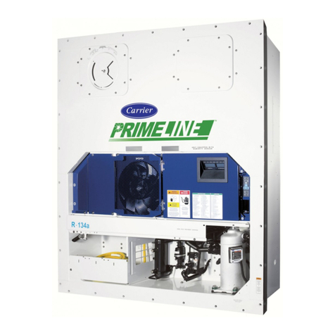
Carrier 69NT40-541-001 Operation manual

Container Refrigeration
OPERATIONS AND SERVICE
For
69NT40-541-001 TO 199
Container Refrigeration Units
T-316 Rev D


OPERATIONS AND SERVICE
For
69NT40-541-001 TO 199
Container Refrigeration Units
© 2017 Carrier Corporation ● Printed in USA July 2017


i T-316
TABLE OF CONTENTS
PARAGRAPH NUMBER PAGE
SAFETY SUMMARY . . . . . . . . . . . . . . . . . . . . . . . . . . . . . . . . . . . . . . . . . . . . . . . . . . . . . . . . . . . . . . . . . . . 1–1
1.1 GENERAL SAFETY NOTICES . . . . . . . . . . . . . . . . . . . . . . . . . . . . . . . . . . . . . . . . . . . . . . . . . . 1–1
1.2 FIRST AID . . . . . . . . . . . . . . . . . . . . . . . . . . . . . . . . . . . . . . . . . . . . . . . . . . . . . . . . . . . . . . . . . . 1–1
1.3 OPERATING PRECAUTIONS . . . . . . . . . . . . . . . . . . . . . . . . . . . . . . . . . . . . . . . . . . . . . . . . . . . 1–1
1.4 MAINTENANCE PRECAUTIONS . . . . . . . . . . . . . . . . . . . . . . . . . . . . . . . . . . . . . . . . . . . . . . . . 1–1
1.5 UNIT LABEL IDENTIFICATION . . . . . . . . . . . . . . . . . . . . . . . . . . . . . . . . . . . . . . . . . . . . . . . . . . 1–1
1.6 SPECIFIC WARNING AND CAUTION STATEMENTS . . . . . . . . . . . . . . . . . . . . . . . . . . . . . . . . 1–2
INTRODUCTION . . . . . . . . . . . . . . . . . . . . . . . . . . . . . . . . . . . . . . . . . . . . . . . . . . . . . . . . . . . . . . . . . . . . . . 2–1
2.1 INTRODUCTION . . . . . . . . . . . . . . . . . . . . . . . . . . . . . . . . . . . . . . . . . . . . . . . . . . . . . . . . . . . . . 2–1
2.2 CONFIGURATION IDENTIFICATION . . . . . . . . . . . . . . . . . . . . . . . . . . . . . . . . . . . . . . . . . . . . . 2–1
2.3 OPTION DESCRIPTION . . . . . . . . . . . . . . . . . . . . . . . . . . . . . . . . . . . . . . . . . . . . . . . . . . . . . . . 2–1
2.3.1 Battery . . . . . . . . . . . . . . . . . . . . . . . . . . . . . . . . . . . . . . . . . . . . . . . . . . . . . . . . . . . . . . . . . 2–1
2.3.2 Dehumidification . . . . . . . . . . . . . . . . . . . . . . . . . . . . . . . . . . . . . . . . . . . . . . . . . . . . . . . . . 2–1
2.3.3 Control Box . . . . . . . . . . . . . . . . . . . . . . . . . . . . . . . . . . . . . . . . . . . . . . . . . . . . . . . . . . . . . 2–1
2.3.4 Temperature Readout . . . . . . . . . . . . . . . . . . . . . . . . . . . . . . . . . . . . . . . . . . . . . . . . . . . . . 2–1
2.3.5 Pressure Readout . . . . . . . . . . . . . . . . . . . . . . . . . . . . . . . . . . . . . . . . . . . . . . . . . . . . . . . . 2–1
2.3.6 USDA . . . . . . . . . . . . . . . . . . . . . . . . . . . . . . . . . . . . . . . . . . . . . . . . . . . . . . . . . . . . . . . . . . 2–1
2.3.7 Interrogator . . . . . . . . . . . . . . . . . . . . . . . . . . . . . . . . . . . . . . . . . . . . . . . . . . . . . . . . . . . . . 2–1
2.3.8 Remote Monitoring . . . . . . . . . . . . . . . . . . . . . . . . . . . . . . . . . . . . . . . . . . . . . . . . . . . . . . . . 2–2
2.3.9 Communications . . . . . . . . . . . . . . . . . . . . . . . . . . . . . . . . . . . . . . . . . . . . . . . . . . . . . . . . . 2–2
2.3.10 Compressor . . . . . . . . . . . . . . . . . . . . . . . . . . . . . . . . . . . . . . . . . . . . . . . . . . . . . . . . . . . . . 2–2
2.3.11 Condenser Coil . . . . . . . . . . . . . . . . . . . . . . . . . . . . . . . . . . . . . . . . . . . . . . . . . . . . . . . . . . 2–2
2.3.12 Autotransformer . . . . . . . . . . . . . . . . . . . . . . . . . . . . . . . . . . . . . . . . . . . . . . . . . . . . . . . . . . 2–2
2.3.13 Temperature Recorder . . . . . . . . . . . . . . . . . . . . . . . . . . . . . . . . . . . . . . . . . . . . . . . . . . . . . 2–2
2.3.14 Gutters . . . . . . . . . . . . . . . . . . . . . . . . . . . . . . . . . . . . . . . . . . . . . . . . . . . . . . . . . . . . . . . . . 2–2
2.3.15 Handles . . . . . . . . . . . . . . . . . . . . . . . . . . . . . . . . . . . . . . . . . . . . . . . . . . . . . . . . . . . . . . . . 2–2
2.3.16 Thermometer Port . . . . . . . . . . . . . . . . . . . . . . . . . . . . . . . . . . . . . . . . . . . . . . . . . . . . . . . . 2–2
2.3.17 Water Cooling . . . . . . . . . . . . . . . . . . . . . . . . . . . . . . . . . . . . . . . . . . . . . . . . . . . . . . . . . . . 2–2
2.3.18 Back Panels . . . . . . . . . . . . . . . . . . . . . . . . . . . . . . . . . . . . . . . . . . . . . . . . . . . . . . . . . . . . . 2–2
2.3.19 460 Volt Cable . . . . . . . . . . . . . . . . . . . . . . . . . . . . . . . . . . . . . . . . . . . . . . . . . . . . . . . . . . . 2–2
2.3.20 230 Volt Cable . . . . . . . . . . . . . . . . . . . . . . . . . . . . . . . . . . . . . . . . . . . . . . . . . . . . . . . . . . . 2–2
2.3.21 Cable Restraint . . . . . . . . . . . . . . . . . . . . . . . . . . . . . . . . . . . . . . . . . . . . . . . . . . . . . . . . . . 2–2
2.3.22 Upper Air (Fresh Air Make Up) . . . . . . . . . . . . . . . . . . . . . . . . . . . . . . . . . . . . . . . . . . . . . . 2–3
2.3.23 Lower Air (Fresh Air Make Up) . . . . . . . . . . . . . . . . . . . . . . . . . . . . . . . . . . . . . . . . . . . . . . 2–3
2.3.24 Arctic Mode . . . . . . . . . . . . . . . . . . . . . . . . . . . . . . . . . . . . . . . . . . . . . . . . . . . . . . . . . . . . . 2–3
2.3.25 Power Correction . . . . . . . . . . . . . . . . . . . . . . . . . . . . . . . . . . . . . . . . . . . . . . . . . . . . . . . . . 2–3
2.3.26 Evaporator . . . . . . . . . . . . . . . . . . . . . . . . . . . . . . . . . . . . . . . . . . . . . . . . . . . . . . . . . . . . . . 2–3
2.3.27 Evaporator Fan Operation . . . . . . . . . . . . . . . . . . . . . . . . . . . . . . . . . . . . . . . . . . . . . . . . . . 2–3
2.3.28 Labels . . . . . . . . . . . . . . . . . . . . . . . . . . . . . . . . . . . . . . . . . . . . . . . . . . . . . . . . . . . . . . . . . 2–3
2.3.29 Plate Set . . . . . . . . . . . . . . . . . . . . . . . . . . . . . . . . . . . . . . . . . . . . . . . . . . . . . . . . . . . . . . . 2–3
2.3.30 Controller . . . . . . . . . . . . . . . . . . . . . . . . . . . . . . . . . . . . . . . . . . . . . . . . . . . . . . . . . . . . . . . 2–3
2.3.31 Condenser Grille . . . . . . . . . . . . . . . . . . . . . . . . . . . . . . . . . . . . . . . . . . . . . . . . . . . . . . . . . 2–3
DESCRIPTION . . . . . . . . . . . . . . . . . . . . . . . . . . . . . . . . . . . . . . . . . . . . . . . . . . . . . . . . . . . . . . . . . . . . . . . . 3–1
3.1 GENERAL DESCRIPTION . . . . . . . . . . . . . . . . . . . . . . . . . . . . . . . . . . . . . . . . . . . . . . . . . . . . . . 3–1

T-316 ii
3.1.1 Refrigeration Unit - Front Section . . . . . . . . . . . . . . . . . . . . . . . . . . . . . . . . . . . . . . . . . . . . .3–1
3.1.2 Fresh Air Makeup Vent . . . . . . . . . . . . . . . . . . . . . . . . . . . . . . . . . . . . . . . . . . . . . . . . . . . . . 3–1
3.1.3 Evaporator Section . . . . . . . . . . . . . . . . . . . . . . . . . . . . . . . . . . . . . . . . . . . . . . . . . . . . . . . . 3–2
3.1.4 Compressor Section . . . . . . . . . . . . . . . . . . . . . . . . . . . . . . . . . . . . . . . . . . . . . . . . . . . . . . . 3–3
3.1.5 Air-Cooled Condenser Section . . . . . . . . . . . . . . . . . . . . . . . . . . . . . . . . . . . . . . . . . . . . . . . 3–4
3.1.6 Water-Cooled Condenser Section . . . . . . . . . . . . . . . . . . . . . . . . . . . . . . . . . . . . . . . . . . . . 3–5
3.1.7 Control Box Section . . . . . . . . . . . . . . . . . . . . . . . . . . . . . . . . . . . . . . . . . . . . . . . . . . . . . . . 3–6
3.1.8 Communications Interface Module . . . . . . . . . . . . . . . . . . . . . . . . . . . . . . . . . . . . . . . . . . . . 3–6
3.2 REFRIGERATION SYSTEM DATA . . . . . . . . . . . . . . . . . . . . . . . . . . . . . . . . . . . . . . . . . . . . . . . 3–7
3.3 ELECTRICAL DATA . . . . . . . . . . . . . . . . . . . . . . . . . . . . . . . . . . . . . . . . . . . . . . . . . . . . . . . . . . . 3–8
3.4 SAFETY AND PROTECTIVE DEVICES . . . . . . . . . . . . . . . . . . . . . . . . . . . . . . . . . . . . . . . . . . . . 3–9
3.5 REFRIGERATION CIRCUIT . . . . . . . . . . . . . . . . . . . . . . . . . . . . . . . . . . . . . . . . . . . . . . . . . . . . 3–10
MICROPROCESSOR . . . . . . . . . . . . . . . . . . . . . . . . . . . . . . . . . . . . . . . . . . . . . . . . . . . . . . . . . . . . . . . . . . . 4–1
4.1 TEMPERATURE CONTROL MICROPROCESSOR SYSTEM . . . . . . . . . . . . . . . . . . . . . . . . . . . 4–1
4.1.1 Key Pad . . . . . . . . . . . . . . . . . . . . . . . . . . . . . . . . . . . . . . . . . . . . . . . . . . . . . . . . . . . . . . . . 4–2
4.1.2 Display Module . . . . . . . . . . . . . . . . . . . . . . . . . . . . . . . . . . . . . . . . . . . . . . . . . . . . . . . . . . . 4–3
4.1.3 Controller . . . . . . . . . . . . . . . . . . . . . . . . . . . . . . . . . . . . . . . . . . . . . . . . . . . . . . . . . . . . . . . 4–4
4.2 CONTROLLER SOFTWARE . . . . . . . . . . . . . . . . . . . . . . . . . . . . . . . . . . . . . . . . . . . . . . . . . . . . 4–4
4.2.1 Configuration Software (Configuration Variables) . . . . . . . . . . . . . . . . . . . . . . . . . . . . . . . . . 4–4
4.2.2 Operational Software (Function Codes) . . . . . . . . . . . . . . . . . . . . . . . . . . . . . . . . . . . . . . . . 4–4
4.3 MODES OF OPERATION . . . . . . . . . . . . . . . . . . . . . . . . . . . . . . . . . . . . . . . . . . . . . . . . . . . . . . . 4–5
4.3.1 Temperature Control - Perishable Mode . . . . . . . . . . . . . . . . . . . . . . . . . . . . . . . . . . . . . . . . 4–5
4.3.2 Evaporator Fan Operation . . . . . . . . . . . . . . . . . . . . . . . . . . . . . . . . . . . . . . . . . . . . . . . . . .4–5
4.3.3 Defrost Interval . . . . . . . . . . . . . . . . . . . . . . . . . . . . . . . . . . . . . . . . . . . . . . . . . . . . . . . . . . . 4–5
4.3.4 Failure Action . . . . . . . . . . . . . . . . . . . . . . . . . . . . . . . . . . . . . . . . . . . . . . . . . . . . . . . . . . . . 4–5
4.3.5 Generator Protection . . . . . . . . . . . . . . . . . . . . . . . . . . . . . . . . . . . . . . . . . . . . . . . . . . . . . . . 4–5
4.3.6 Condenser Pressure Control . . . . . . . . . . . . . . . . . . . . . . . . . . . . . . . . . . . . . . . . . . . . . . . . 4–6
4.3.7 Arctic Mode . . . . . . . . . . . . . . . . . . . . . . . . . . . . . . . . . . . . . . . . . . . . . . . . . . . . . . . . . . . . . . 4–6
4.3.8 Perishable Mode - Conventional . . . . . . . . . . . . . . . . . . . . . . . . . . . . . . . . . . . . . . . . . . . . . . 4–6
4.3.9 Perishable Mode - Economy . . . . . . . . . . . . . . . . . . . . . . . . . . . . . . . . . . . . . . . . . . . . . . . . . 4–6
4.3.10 Perishable Mode - Dehumidification . . . . . . . . . . . . . . . . . . . . . . . . . . . . . . . . . . . . . . . . . . . 4–7
4.3.11 Perishable, Dehumidification - Bulb Mode . . . . . . . . . . . . . . . . . . . . . . . . . . . . . . . . . . . . . . 4–7
4.3.12 Temperature Control - Frozen Mode . . . . . . . . . . . . . . . . . . . . . . . . . . . . . . . . . . . . . . . . . . 4–8
4.3.13 Frozen Mode - Conventional . . . . . . . . . . . . . . . . . . . . . . . . . . . . . . . . . . . . . . . . . . . . . . . . .4–8
4.3.14 Frozen Mode - Economy . . . . . . . . . . . . . . . . . . . . . . . . . . . . . . . . . . . . . . . . . . . . . . . . . . . . 4–8
4.4 CONTROLLER ALARMS . . . . . . . . . . . . . . . . . . . . . . . . . . . . . . . . . . . . . . . . . . . . . . . . . . . . . . . 4–8
4.5 UNIT PRE-TRIP DIAGNOSTICS . . . . . . . . . . . . . . . . . . . . . . . . . . . . . . . . . . . . . . . . . . . . . . . . . 4–9
4.6 DATACORDER . . . . . . . . . . . . . . . . . . . . . . . . . . . . . . . . . . . . . . . . . . . . . . . . . . . . . . . . . . . . . . 4–10
4.6.1 Description . . . . . . . . . . . . . . . . . . . . . . . . . . . . . . . . . . . . . . . . . . . . . . . . . . . . . . . . . . . . . 4–10
4.6.2 DataCORDER Software . . . . . . . . . . . . . . . . . . . . . . . . . . . . . . . . . . . . . . . . . . . . . . . . . . . 4–11
4.6.3 Sensor Configuration (dCF02) . . . . . . . . . . . . . . . . . . . . . . . . . . . . . . . . . . . . . . . . . . . . . . 4–11
4.6.4 Logging Interval (dCF03) . . . . . . . . . . . . . . . . . . . . . . . . . . . . . . . . . . . . . . . . . . . . . . . . . .4–14
4.6.5 Thermistor Format (dCF04) . . . . . . . . . . . . . . . . . . . . . . . . . . . . . . . . . . . . . . . . . . . . . . . . 4–14
4.6.6 Sampling Type (dCF05 & dCF06) . . . . . . . . . . . . . . . . . . . . . . . . . . . . . . . . . . . . . . . . . . . . 4–14
4.6.7 Alarm Configuration (dCF07 - dCF10) . . . . . . . . . . . . . . . . . . . . . . . . . . . . . . . . . . . . . . . . 4–14
4.6.8 DataCORDER Power-Up . . . . . . . . . . . . . . . . . . . . . . . . . . . . . . . . . . . . . . . . . . . . . . . . . . 4–14
4.6.9 Pre-Trip Data Recording . . . . . . . . . . . . . . . . . . . . . . . . . . . . . . . . . . . . . . . . . . . . . . . . . . .4–14
4.6.10 DataCORDER Communications . . . . . . . . . . . . . . . . . . . . . . . . . . . . . . . . . . . . . . . . . . . . . 4–15
iii T-316
4.6.11 USDA Cold Treatment . . . . . . . . . . . . . . . . . . . . . . . . . . . . . . . . . . . . . . . . . . . . . . . . . . . . 4–15
4.6.12 USDA Cold Treatment Procedure . . . . . . . . . . . . . . . . . . . . . . . . . . . . . . . . . . . . . . . . . . . 4–16
4.6.13 DataCORDER Alarms . . . . . . . . . . . . . . . . . . . . . . . . . . . . . . . . . . . . . . . . . . . . . . . . . . . . 4–17
OPERATION . . . . . . . . . . . . . . . . . . . . . . . . . . . . . . . . . . . . . . . . . . . . . . . . . . . . . . . . . . . . . . . . . . . . . . . . . 5–1
5.1 INSPECTION (BEFORE STARTING) . . . . . . . . . . . . . . . . . . . . . . . . . . . . . . . . . . . . . . . . . . . . . 5–1
5.2 CONNECT POWER . . . . . . . . . . . . . . . . . . . . . . . . . . . . . . . . . . . . . . . . . . . . . . . . . . . . . . . . . . . 5–1
5.2.1 Connection To 380/460 vac Power . . . . . . . . . . . . . . . . . . . . . . . . . . . . . . . . . . . . . . . . . . . 5–1
5.2.2 Connection to 190/230 vac Power . . . . . . . . . . . . . . . . . . . . . . . . . . . . . . . . . . . . . . . . . . . . 5–1
5.3 ADJUST FRESH AIR MAKEUP VENT . . . . . . . . . . . . . . . . . . . . . . . . . . . . . . . . . . . . . . . . . . . . 5–2
5.3.1 Upper Fresh Air Makeup Vent . . . . . . . . . . . . . . . . . . . . . . . . . . . . . . . . . . . . . . . . . . . . . . . 5–2
5.3.2 Lower Fresh Air Makeup Vent . . . . . . . . . . . . . . . . . . . . . . . . . . . . . . . . . . . . . . . . . . . . . . . 5–3
5.3.3 Fresh Air Position Sensor . . . . . . . . . . . . . . . . . . . . . . . . . . . . . . . . . . . . . . . . . . . . . . . . . . 5–4
5.4 CONNECT WATER-COOLED CONDENSER . . . . . . . . . . . . . . . . . . . . . . . . . . . . . . . . . . . . . . . 5–4
5.4.1 Water-Cooled Condenser with Water Pressure Switch . . . . . . . . . . . . . . . . . . . . . . . . . . . . 5–4
5.4.2 Water-Cooled Condenser with Condenser Fan Switch . . . . . . . . . . . . . . . . . . . . . . . . . . . . 5–4
5.5 CONNECT REMOTE MONITORING RECEPTACLE . . . . . . . . . . . . . . . . . . . . . . . . . . . . . . . . . 5–5
5.6 STARTING AND STOPPING INSTRUCTIONS . . . . . . . . . . . . . . . . . . . . . . . . . . . . . . . . . . . . . . 5–5
5.6.1 Starting the Unit . . . . . . . . . . . . . . . . . . . . . . . . . . . . . . . . . . . . . . . . . . . . . . . . . . . . . . . . . . 5–5
5.6.2 Stopping the Unit . . . . . . . . . . . . . . . . . . . . . . . . . . . . . . . . . . . . . . . . . . . . . . . . . . . . . . . . . 5–5
5.7 START-UP INSPECTION . . . . . . . . . . . . . . . . . . . . . . . . . . . . . . . . . . . . . . . . . . . . . . . . . . . . . . 5–5
5.7.1 Physical Inspection . . . . . . . . . . . . . . . . . . . . . . . . . . . . . . . . . . . . . . . . . . . . . . . . . . . . . . . 5–5
5.7.2 Check Controller Function Codes . . . . . . . . . . . . . . . . . . . . . . . . . . . . . . . . . . . . . . . . . . . . 5–5
5.7.3 Start Temperature Recorder . . . . . . . . . . . . . . . . . . . . . . . . . . . . . . . . . . . . . . . . . . . . . . . . 5–5
5.7.4 Complete Inspection . . . . . . . . . . . . . . . . . . . . . . . . . . . . . . . . . . . . . . . . . . . . . . . . . . . . . . 5–6
5.8 PRE-TRIP DIAGNOSIS . . . . . . . . . . . . . . . . . . . . . . . . . . . . . . . . . . . . . . . . . . . . . . . . . . . . . . . . 5–6
5.9 OBSERVE UNIT OPERATION . . . . . . . . . . . . . . . . . . . . . . . . . . . . . . . . . . . . . . . . . . . . . . . . . . 5–8
5.9.1 Crankcase Heater . . . . . . . . . . . . . . . . . . . . . . . . . . . . . . . . . . . . . . . . . . . . . . . . . . . . . . . . 5–8
5.9.2 Probe Check . . . . . . . . . . . . . . . . . . . . . . . . . . . . . . . . . . . . . . . . . . . . . . . . . . . . . . . . . . . . 5–8
5.10 SEQUENCE OF OPERATION . . . . . . . . . . . . . . . . . . . . . . . . . . . . . . . . . . . . . . . . . . . . . . . . . . . 5–8
5.10.1 Sequence of Operation - Perishable Mode Cooling . . . . . . . . . . . . . . . . . . . . . . . . . . . . . . 5–10
5.10.2 Sequence of Operation - Perishable Mode Heating . . . . . . . . . . . . . . . . . . . . . . . . . . . . . 5–11
5.10.3 Sequence of Operation - Frozen Mode Cooling . . . . . . . . . . . . . . . . . . . . . . . . . . . . . . . . 5–11
5.10.4 Sequence of Operation - Defrost . . . . . . . . . . . . . . . . . . . . . . . . . . . . . . . . . . . . . . . . . . . . 5–12
5.11 EMERGENCY OPERATION . . . . . . . . . . . . . . . . . . . . . . . . . . . . . . . . . . . . . . . . . . . . . . . . . . . 5–14
5.11.1 Emergency Bypass Operation . . . . . . . . . . . . . . . . . . . . . . . . . . . . . . . . . . . . . . . . . . . . . . 5–14
5.11.2 Emergency Defrost Operation. . . . . . . . . . . . . . . . . . . . . . . . . . . . . . . . . . . . . . . . . . . . . . 5–14
TROUBLESHOOTING . . . . . . . . . . . . . . . . . . . . . . . . . . . . . . . . . . . . . . . . . . . . . . . . . . . . . . . . . . . . . . . . . . 6–1
6.1 UNIT WILL NOT START OR STARTS THEN STOPS . . . . . . . . . . . . . . . . . . . . . . . . . . . . . . . . . 6–1
6.2 UNIT OPERATES LONG OR CONTINUOUSLY IN COOLING . . . . . . . . . . . . . . . . . . . . . . . . . . 6–1
6.3 UNIT RUNS BUT HAS INSUFFICIENT COOLING . . . . . . . . . . . . . . . . . . . . . . . . . . . . . . . . . . . 6–2
6.4 UNIT WILL NOT HEAT OR HAS INSUFFICIENT HEATING . . . . . . . . . . . . . . . . . . . . . . . . . . . . 6–2
6.5 UNIT WILL NOT TERMINATE HEATING . . . . . . . . . . . . . . . . . . . . . . . . . . . . . . . . . . . . . . . . . . 6–2
6.6 UNIT WILL NOT DEFROST PROPERLY . . . . . . . . . . . . . . . . . . . . . . . . . . . . . . . . . . . . . . . . . . 6–2
6.7 ABNORMAL PRESSURES (COOLING) . . . . . . . . . . . . . . . . . . . . . . . . . . . . . . . . . . . . . . . . . . . 6–3
6.8 ABNORMAL NOISE OR VIBRATIONS . . . . . . . . . . . . . . . . . . . . . . . . . . . . . . . . . . . . . . . . . . . . 6–3
6.9 CONTROLLER MALFUNCTION . . . . . . . . . . . . . . . . . . . . . . . . . . . . . . . . . . . . . . . . . . . . . . . . . 6–3
6.10 NO EVAPORATOR AIR FLOW OR RESTRICTED AIR FLOW . . . . . . . . . . . . . . . . . . . . . . . . . . 6–4
6.11 THERMOSTATIC EXPANSION VALVE MALFUNCTION . . . . . . . . . . . . . . . . . . . . . . . . . . . . . . 6–4

T-316 iv
6.12 AUTOTRANSFORMER MALFUNCTION . . . . . . . . . . . . . . . . . . . . . . . . . . . . . . . . . . . . . . . . . . . 6–4
6.13 WATER-COOLED CONDENSER OR WATER PRESSURE SWITCH . . . . . . . . . . . . . . . . . . . . . 6–4
SERVICE . . . . . . . . . . . . . . . . . . . . . . . . . . . . . . . . . . . . . . . . . . . . . . . . . . . . . . . . . . . . . . . . . . . . . . . . . . . . . 7–1
7.1 SECTION LAYOUT . . . . . . . . . . . . . . . . . . . . . . . . . . . . . . . . . . . . . . . . . . . . . . . . . . . . . . . . . . . . 7–1
7.2 SERVICE VALVES . . . . . . . . . . . . . . . . . . . . . . . . . . . . . . . . . . . . . . . . . . . . . . . . . . . . . . . . . . . . 7–1
7.3 MANIFOLD GAUGE SET . . . . . . . . . . . . . . . . . . . . . . . . . . . . . . . . . . . . . . . . . . . . . . . . . . . . . . . 7–2
7.4 PUMPING THE UNIT DOWN . . . . . . . . . . . . . . . . . . . . . . . . . . . . . . . . . . . . . . . . . . . . . . . . . . . .7–4
7.5 REFRIGERANT LEAK CHECKING . . . . . . . . . . . . . . . . . . . . . . . . . . . . . . . . . . . . . . . . . . . . . . . 7–5
7.6 EVACUATION AND DEHYDRATION . . . . . . . . . . . . . . . . . . . . . . . . . . . . . . . . . . . . . . . . . . . . . . 7–5
7.6.1 General . . . . . . . . . . . . . . . . . . . . . . . . . . . . . . . . . . . . . . . . . . . . . . . . . . . . . . . . . . . . . . . . . 7–5
7.6.2 Preparation . . . . . . . . . . . . . . . . . . . . . . . . . . . . . . . . . . . . . . . . . . . . . . . . . . . . . . . . . . . . . . 7–5
7.6.3 Procedure - Complete System . . . . . . . . . . . . . . . . . . . . . . . . . . . . . . . . . . . . . . . . . . . . . . . 7–6
7.6.4 Procedure - Partial System . . . . . . . . . . . . . . . . . . . . . . . . . . . . . . . . . . . . . . . . . . . . . . . . . . 7–7
7.7 REFRIGERANT CHARGE . . . . . . . . . . . . . . . . . . . . . . . . . . . . . . . . . . . . . . . . . . . . . . . . . . . . . .7–7
7.7.1 Checking the Refrigerant Charge . . . . . . . . . . . . . . . . . . . . . . . . . . . . . . . . . . . . . . . . . . . . . 7–7
7.7.2 Adding Refrigerant to System (Full Charge) . . . . . . . . . . . . . . . . . . . . . . . . . . . . . . . . . . . . . 7–7
7.7.3 Adding Refrigerant to System (Partial Charge) . . . . . . . . . . . . . . . . . . . . . . . . . . . . . . . . . . . 7–8
7.8 COMPRESSOR . . . . . . . . . . . . . . . . . . . . . . . . . . . . . . . . . . . . . . . . . . . . . . . . . . . . . . . . . . . . . . 7–8
7.8.1 Removal and Replacement of Compressor . . . . . . . . . . . . . . . . . . . . . . . . . . . . . . . . . . . . . 7–8
7.8.2 Compressor Disassembly . . . . . . . . . . . . . . . . . . . . . . . . . . . . . . . . . . . . . . . . . . . . . . . . . . 7–10
7.8.3 Compressor Reassembly . . . . . . . . . . . . . . . . . . . . . . . . . . . . . . . . . . . . . . . . . . . . . . . . . . 7–14
7.8.4 Preparation . . . . . . . . . . . . . . . . . . . . . . . . . . . . . . . . . . . . . . . . . . . . . . . . . . . . . . . . . . . . . 7–14
7.8.5 Installing the Components . . . . . . . . . . . . . . . . . . . . . . . . . . . . . . . . . . . . . . . . . . . . . . . . .7–15
7.8.6 Compressor Oil Level . . . . . . . . . . . . . . . . . . . . . . . . . . . . . . . . . . . . . . . . . . . . . . . . . . . . . 7–16
7.9 HIGH PRESSURE SWITCH . . . . . . . . . . . . . . . . . . . . . . . . . . . . . . . . . . . . . . . . . . . . . . . . . . . . 7–17
7.9.1 Replacing High Pressure Switch . . . . . . . . . . . . . . . . . . . . . . . . . . . . . . . . . . . . . . . . . . . . . 7–17
7.9.2 Checking High Pressure Switch . . . . . . . . . . . . . . . . . . . . . . . . . . . . . . . . . . . . . . . . . . . . . 7–17
7.10 CONDENSER COIL . . . . . . . . . . . . . . . . . . . . . . . . . . . . . . . . . . . . . . . . . . . . . . . . . . . . . . . . . . 7–17
7.11 CONDENSER FAN AND MOTOR ASSEMBLY . . . . . . . . . . . . . . . . . . . . . . . . . . . . . . . . . . . . . 7–18
7.12 WATER-COOLED CONDENSER CLEANING . . . . . . . . . . . . . . . . . . . . . . . . . . . . . . . . . . . . . . 7–18
7.13 FILTER-DRIER . . . . . . . . . . . . . . . . . . . . . . . . . . . . . . . . . . . . . . . . . . . . . . . . . . . . . . . . . . . . . . 7–21
7.14 THERMOSTATIC EXPANSION VALVE . . . . . . . . . . . . . . . . . . . . . . . . . . . . . . . . . . . . . . . . . . . 7–21
7.14.1 Checking Superheat. . . . . . . . . . . . . . . . . . . . . . . . . . . . . . . . . . . . . . . . . . . . . . . . . . . . . . 7–22
7.14.2 Hermetic Valve Replacement . . . . . . . . . . . . . . . . . . . . . . . . . . . . . . . . . . . . . . . . . . . . . . . 7–22
7.15 EVAPORATOR COIL AND HEATER ASSEMBLY . . . . . . . . . . . . . . . . . . . . . . . . . . . . . . . . . . . 7–23
7.15.1 Evaporator Coil Replacement . . . . . . . . . . . . . . . . . . . . . . . . . . . . . . . . . . . . . . . . . . . . . . . 7–23
7.15.2 Evaporator Heater Replacement . . . . . . . . . . . . . . . . . . . . . . . . . . . . . . . . . . . . . . . . . . . . 7–24
7.16 EVAPORATOR FAN AND MOTOR ASSEMBLY . . . . . . . . . . . . . . . . . . . . . . . . . . . . . . . . . . . . 7–24
7.16.1 Replacing The Evaporator Fan Assembly . . . . . . . . . . . . . . . . . . . . . . . . . . . . . . . . . . . . . 7–24
7.16.2 Disassemble The Evaporator Fan Assembly . . . . . . . . . . . . . . . . . . . . . . . . . . . . . . . . . . . 7–24
7.16.3 Assemble The Evaporator Fan Assembly . . . . . . . . . . . . . . . . . . . . . . . . . . . . . . . . . . . . . . 7–25
7.17 EVAPORATOR FAN MOTOR CAPACITORS . . . . . . . . . . . . . . . . . . . . . . . . . . . . . . . . . . . . . . 7–25
7.17.1 When To Check For A Defective Capacitor . . . . . . . . . . . . . . . . . . . . . . . . . . . . . . . . . . . . 7–25
7.17.2 Removing The Capacitor . . . . . . . . . . . . . . . . . . . . . . . . . . . . . . . . . . . . . . . . . . . . . . . . . .7–26
7.17.3 Checking The Capacitor . . . . . . . . . . . . . . . . . . . . . . . . . . . . . . . . . . . . . . . . . . . . . . . . . . .7–26
7.18 SUCTION MODULATION VALVE . . . . . . . . . . . . . . . . . . . . . . . . . . . . . . . . . . . . . . . . . . . . . . . . 7–26
7.18.1 Precheck Procedure . . . . . . . . . . . . . . . . . . . . . . . . . . . . . . . . . . . . . . . . . . . . . . . . . . . . . . 7–27
7.18.2 Checking The Stepper Valve . . . . . . . . . . . . . . . . . . . . . . . . . . . . . . . . . . . . . . . . . . . . . . . 7–27

v T-316
7.18.3 Checking The Controller . . . . . . . . . . . . . . . . . . . . . . . . . . . . . . . . . . . . . . . . . . . . . . . . . . 7–28
7.18.4 Emergency Repair Procedures: . . . . . . . . . . . . . . . . . . . . . . . . . . . . . . . . . . . . . . . . . . . . . 7–28
7.19 AUTOTRANSFORMER . . . . . . . . . . . . . . . . . . . . . . . . . . . . . . . . . . . . . . . . . . . . . . . . . . . . . . . 7–28
7.20 CONTROLLER . . . . . . . . . . . . . . . . . . . . . . . . . . . . . . . . . . . . . . . . . . . . . . . . . . . . . . . . . . . . . 7–29
7.20.1 Handling Controller . . . . . . . . . . . . . . . . . . . . . . . . . . . . . . . . . . . . . . . . . . . . . . . . . . . . . . 7–29
7.20.2 Controller Trouble-Shooting . . . . . . . . . . . . . . . . . . . . . . . . . . . . . . . . . . . . . . . . . . . . . . . . 7–30
7.20.3 Controller Programming Procedure . . . . . . . . . . . . . . . . . . . . . . . . . . . . . . . . . . . . . . . . . . 7–30
7.20.4 Removing and Installing the Controller . . . . . . . . . . . . . . . . . . . . . . . . . . . . . . . . . . . . . . . 7–31
7.20.5 Battery Replacement . . . . . . . . . . . . . . . . . . . . . . . . . . . . . . . . . . . . . . . . . . . . . . . . . . . . . 7–32
7.21 TEMPERATURE SENSOR SERVICE . . . . . . . . . . . . . . . . . . . . . . . . . . . . . . . . . . . . . . . . . . . . 7–32
7.21.1 Sensor Checkout Procedure . . . . . . . . . . . . . . . . . . . . . . . . . . . . . . . . . . . . . . . . . . . . . . . 7–32
7.21.2 Sensor Replacement . . . . . . . . . . . . . . . . . . . . . . . . . . . . . . . . . . . . . . . . . . . . . . . . . . . . . 7–32
7.21.3 Sensor Re-Installation . . . . . . . . . . . . . . . . . . . . . . . . . . . . . . . . . . . . . . . . . . . . . . . . . . . . 7–34
7.22 VENT POSITION SENSOR (VPS) . . . . . . . . . . . . . . . . . . . . . . . . . . . . . . . . . . . . . . . . . . . . . . . 7–35
7.23 ELECTRONIC PARTLOW TEMPERATURE RECORDER . . . . . . . . . . . . . . . . . . . . . . . . . . . . 7–36
7.23.1 Replacing the Recorder . . . . . . . . . . . . . . . . . . . . . . . . . . . . . . . . . . . . . . . . . . . . . . . . . . . 7–37
7.23.2 Changing the Chart . . . . . . . . . . . . . . . . . . . . . . . . . . . . . . . . . . . . . . . . . . . . . . . . . . . . . . 7–37
7.23.3 Adjusting the Recorder Stylus . . . . . . . . . . . . . . . . . . . . . . . . . . . . . . . . . . . . . . . . . . . . . . 7–38
7.23.4 Re-zeroing the Recording Thermometer . . . . . . . . . . . . . . . . . . . . . . . . . . . . . . . . . . . . . . 7–38
7.24 MAINTENANCE OF PAINTED SURFACES . . . . . . . . . . . . . . . . . . . . . . . . . . . . . . . . . . . . . . . 7–39
7.25 COMPOSITE CONTROL BOX REPAIRS . . . . . . . . . . . . . . . . . . . . . . . . . . . . . . . . . . . . . . . . . 7–39
7.25.1 Introduction . . . . . . . . . . . . . . . . . . . . . . . . . . . . . . . . . . . . . . . . . . . . . . . . . . . . . . . . . . . . 7–39
7.25.2 Cracks . . . . . . . . . . . . . . . . . . . . . . . . . . . . . . . . . . . . . . . . . . . . . . . . . . . . . . . . . . . . . . . . 7–39
7.25.3 Chips And Holes . . . . . . . . . . . . . . . . . . . . . . . . . . . . . . . . . . . . . . . . . . . . . . . . . . . . . . . . 7–39
7.25.4 Inserts . . . . . . . . . . . . . . . . . . . . . . . . . . . . . . . . . . . . . . . . . . . . . . . . . . . . . . . . . . . . . . . . 7–39
7.25.5 Door Hinge Inserts . . . . . . . . . . . . . . . . . . . . . . . . . . . . . . . . . . . . . . . . . . . . . . . . . . . . . . . 7–40
7.26 COMMUNICATIONS INTERFACE MODULE INSTALLATION . . . . . . . . . . . . . . . . . . . . . . . . . 7–43
7.27 POWER FACTOR CORRECTOR CAPACITORS (PFC) . . . . . . . . . . . . . . . . . . . . . . . . . . . . . . 7–43
ELECTRICAL WIRING SCHEMATICS . . . . . . . . . . . . . . . . . . . . . . . . . . . . . . . . . . . . . . . . . . . . . . . . . . . . . 8–1
8.1 INTRODUCTION . . . . . . . . . . . . . . . . . . . . . . . . . . . . . . . . . . . . . . . . . . . . . . . . . . . . . . . . . . . . . 8–1
INDEX . . . . . . . . . . . . . . . . . . . . . . . . . . . . . . . . . . . . . . . . . . . . . . . . . . . . . . . . . . . . . . . . . . . . . . . . . . . INDEX–1

T-316 vi

T-316 vii
LIST OF ILLUSTRATIONS
FIGURE NUMBER Page
Figure 3.1 Refrigeration Unit - Front Section . . . . . . . . . . . . . . . . . . . . . . . . . . . . . . . . . . . . . . . . . . . . . . . . . . 3–1
Figure 3.2 Evaporator Section . . . . . . . . . . . . . . . . . . . . . . . . . . . . . . . . . . . . . . . . . . . . . . . . . . . . . . . . . . . . . 3–2
Figure 3.3 Compressor Section . . . . . . . . . . . . . . . . . . . . . . . . . . . . . . . . . . . . . . . . . . . . . . . . . . . . . . . . . . . . 3–3
Figure 3.4 Air-Cooled Condenser Section . . . . . . . . . . . . . . . . . . . . . . . . . . . . . . . . . . . . . . . . . . . . . . . . . . . . 3–4
Figure 3.5 Water-Cooled Condenser Section . . . . . . . . . . . . . . . . . . . . . . . . . . . . . . . . . . . . . . . . . . . . . . . . . 3–5
Figure 3.6 Control Box Section . . . . . . . . . . . . . . . . . . . . . . . . . . . . . . . . . . . . . . . . . . . . . . . . . . . . . . . . . . . . 3–6
Figure 3.7 Refrigeration Circuit Schematic . . . . . . . . . . . . . . . . . . . . . . . . . . . . . . . . . . . . . . . . . . . . . . . . . . 3–11
Figure 4.1 Temperature Control System . . . . . . . . . . . . . . . . . . . . . . . . . . . . . . . . . . . . . . . . . . . . . . . . . . . . . 4–1
Figure 4.2 Key Pad . . . . . . . . . . . . . . . . . . . . . . . . . . . . . . . . . . . . . . . . . . . . . . . . . . . . . . . . . . . . . . . . . . . . . 4–2
Figure 4.3 Display Module . . . . . . . . . . . . . . . . . . . . . . . . . . . . . . . . . . . . . . . . . . . . . . . . . . . . . . . . . . . . . . . . 4–3
Figure 4.4 Micro-Link 3 Controller . . . . . . . . . . . . . . . . . . . . . . . . . . . . . . . . . . . . . . . . . . . . . . . . . . . . . . . . . . 4–3
Figure 4.5 Standard Configuration Report . . . . . . . . . . . . . . . . . . . . . . . . . . . . . . . . . . . . . . . . . . . . . . . . . . . 4–13
Figure 4.6 DataReader . . . . . . . . . . . . . . . . . . . . . . . . . . . . . . . . . . . . . . . . . . . . . . . . . . . . . . . . . . . . . . . . . 4–15
Figure 5.1 Autotransformer . . . . . . . . . . . . . . . . . . . . . . . . . . . . . . . . . . . . . . . . . . . . . . . . . . . . . . . . . . . . . . . 5–2
Figure 5.2 Make Up Air Flow Chart . . . . . . . . . . . . . . . . . . . . . . . . . . . . . . . . . . . . . . . . . . . . . . . . . . . . . . . . . 5–3
Figure 5.3 Controller Operation - Perishable Mode . . . . . . . . . . . . . . . . . . . . . . . . . . . . . . . . . . . . . . . . . . . . . 5–9
Figure 5.4 Controller Operation - Frozen Mode . . . . . . . . . . . . . . . . . . . . . . . . . . . . . . . . . . . . . . . . . . . . . . . . 5–9
Figure 5.5 Perishable Mode Cooling . . . . . . . . . . . . . . . . . . . . . . . . . . . . . . . . . . . . . . . . . . . . . . . . . . . . . . . 5–10
Figure 5.6 Perishable Mode Heating . . . . . . . . . . . . . . . . . . . . . . . . . . . . . . . . . . . . . . . . . . . . . . . . . . . . . . . 5–11
Figure 5.7 Frozen Mode . . . . . . . . . . . . . . . . . . . . . . . . . . . . . . . . . . . . . . . . . . . . . . . . . . . . . . . . . . . . . . . . 5–12
Figure 5.8 Defrost . . . . . . . . . . . . . . . . . . . . . . . . . . . . . . . . . . . . . . . . . . . . . . . . . . . . . . . . . . . . . . . . . . . . . 5–13
Figure 7.1 Service Valve . . . . . . . . . . . . . . . . . . . . . . . . . . . . . . . . . . . . . . . . . . . . . . . . . . . . . . . . . . . . . . . . . 7–1
Figure 7.2 Manifold Gauge Set . . . . . . . . . . . . . . . . . . . . . . . . . . . . . . . . . . . . . . . . . . . . . . . . . . . . . . . . . . . . 7–2
Figure 7.3 R-134a Manifold Gauge/Hose Set . . . . . . . . . . . . . . . . . . . . . . . . . . . . . . . . . . . . . . . . . . . . . . . . . 7–3
Figure 7.4 Refrigeration System Service Connections . . . . . . . . . . . . . . . . . . . . . . . . . . . . . . . . . . . . . . . . . . 7–4
Figure 7.5 Compressor Service Connections . . . . . . . . . . . . . . . . . . . . . . . . . . . . . . . . . . . . . . . . . . . . . . . . . 7–6
Figure 7.6 Compressor . . . . . . . . . . . . . . . . . . . . . . . . . . . . . . . . . . . . . . . . . . . . . . . . . . . . . . . . . . . . . . . . . . 7–9
Figure 7.7 Exploded View of Valve Plate . . . . . . . . . . . . . . . . . . . . . . . . . . . . . . . . . . . . . . . . . . . . . . . . . . . 7–10
Figure 7.8 Bottom Plate Removed . . . . . . . . . . . . . . . . . . . . . . . . . . . . . . . . . . . . . . . . . . . . . . . . . . . . . . . . 7–11
Figure 7.9 Oil Pump and Bearing Head . . . . . . . . . . . . . . . . . . . . . . . . . . . . . . . . . . . . . . . . . . . . . . . . . . . . . 7–12
Figure 7.10 Low Profile Oil Pump . . . . . . . . . . . . . . . . . . . . . . . . . . . . . . . . . . . . . . . . . . . . . . . . . . . . . . . . . 7–12
Figure 7.11 Motor End Cover . . . . . . . . . . . . . . . . . . . . . . . . . . . . . . . . . . . . . . . . . . . . . . . . . . . . . . . . . . . . 7–13
Figure 7.12 Equalizing Tube and Lock Screw Assembly . . . . . . . . . . . . . . . . . . . . . . . . . . . . . . . . . . . . . . .7–13
Figure 7.13 Crankshaft Assembly . . . . . . . . . . . . . . . . . . . . . . . . . . . . . . . . . . . . . . . . . . . . . . . . . . . . . . . . . 7–14
Figure 7.14 Suction Valve & Positioning Springs . . . . . . . . . . . . . . . . . . . . . . . . . . . . . . . . . . . . . . . . . . . . . 7–14
Figure 7.15 Piston Ring . . . . . . . . . . . . . . . . . . . . . . . . . . . . . . . . . . . . . . . . . . . . . . . . . . . . . . . . . . . . . . . . . 7–15
Figure 7.16 High Pressure Switch Testing . . . . . . . . . . . . . . . . . . . . . . . . . . . . . . . . . . . . . . . . . . . . . . . . . . 7–17
Figure 7.17 Water-Cooled Condenser Cleaning - Forced Circulation . . . . . . . . . . . . . . . . . . . . . . . . . . . . . . 7–20
Figure 7.18 Water-cooled Condenser Cleaning - Gravity Circulation . . . . . . . . . . . . . . . . . . . . . . . . . . . . . . 7–20
Figure 7.19 Thermostatic Expansion Valve Bulb . . . . . . . . . . . . . . . . . . . . . . . . . . . . . . . . . . . . . . . . . . . . . . 7–21
Figure 7.20 Thermostatic Expansion Valve . . . . . . . . . . . . . . . . . . . . . . . . . . . . . . . . . . . . . . . . . . . . . . . . . . 7–22
Figure 7.21 Hermetic Thermostatic Expansion Valve Brazing Procedure . . . . . . . . . . . . . . . . . . . . . . . . . . . 7–23

T-316 viii
Figure 7.22 Evaporator Fan Assembly . . . . . . . . . . . . . . . . . . . . . . . . . . . . . . . . . . . . . . . . . . . . . . . . . . . . . 7–25
Figure 7.23 Suction Modulation Valve (SMV) . . . . . . . . . . . . . . . . . . . . . . . . . . . . . . . . . . . . . . . . . . . . . . . . 7–26
Figure 7.24 Controller Section of the Control Box . . . . . . . . . . . . . . . . . . . . . . . . . . . . . . . . . . . . . . . . . . . . . 7–29
Figure 7.25 Sensor Types . . . . . . . . . . . . . . . . . . . . . . . . . . . . . . . . . . . . . . . . . . . . . . . . . . . . . . . . . . . . . . . 7–33
Figure 7.26 Sensor and Cable Splice . . . . . . . . . . . . . . . . . . . . . . . . . . . . . . . . . . . . . . . . . . . . . . . . . . . . . . 7–34
Figure 7.27 Supply Sensor Positioning . . . . . . . . . . . . . . . . . . . . . . . . . . . . . . . . . . . . . . . . . . . . . . . . . . . . . 7–34
Figure 7.28 Return Sensor Positioning . . . . . . . . . . . . . . . . . . . . . . . . . . . . . . . . . . . . . . . . . . . . . . . . . . . . . 7–34
Figure 7.29 Electronic Partlow Temperature Recorder . . . . . . . . . . . . . . . . . . . . . . . . . . . . . . . . . . . . . . . . . 7–37
Figure 7.30 Door Hinge Repair . . . . . . . . . . . . . . . . . . . . . . . . . . . . . . . . . . . . . . . . . . . . . . . . . . . . . . . . . . . 7–40
Figure 7.31 Insert Location . . . . . . . . . . . . . . . . . . . . . . . . . . . . . . . . . . . . . . . . . . . . . . . . . . . . . . . . . . . . . . 7–42
Figure 7.32 Communications Interface Installation . . . . . . . . . . . . . . . . . . . . . . . . . . . . . . . . . . . . . . . . . . . . 7–43
Figure 7.33 R-134a Compressor Pressure and Motor Current Curves vs Ambient Temp (1 of 2) . . . . . . . . 7–48
Figure 7.34 R-134a Compressor Pressure and Motor Current Curves vs Ambient Temp (2 of 2) . . . . . . . . 7–49
Figure 8.1 LEGEND . . . . . . . . . . . . . . . . . . . . . . . . . . . . . . . . . . . . . . . . . . . . . . . . . . . . . . . . . . . . . . . . . . . . . 8–2
Figure 8.2 SCHEMATIC DIAGRAM . . . . . . . . . . . . . . . . . . . . . . . . . . . . . . . . . . . . . . . . . . . . . . . . . . . . . . . . 8–3
Figure 8.3 SCHEMATIC DIAGRAM -- Units with Single Evaporator Fan Capability . . . . . . . . . . . . . . . . . . . . 8–4
Figure 8.4 SCHEMATIC DIAGRAM -- TransFRESH and Vent Position Sensors (VPS) . . . . . . . . . . . . . . . . . 8–5
Figure 8.5 SCHEMATIC DIAGRAM -- Emergency Bypass . . . . . . . . . . . . . . . . . . . . . . . . . . . . . . . . . . . . . . . 8–6
Figure 8.6 SCHEMATIC DIAGRAM, WIRING DIAGRAM-- Electronic Partlow Recorder . . . . . . . . . . . . . . . . 8–7
Figure 8.7 UNIT WIRING DIAGRAM (Sheet 1 of 2) . . . . . . . . . . . . . . . . . . . . . . . . . . . . . . . . . . . . . . . . . . . . 8–8
Figure 8.8 UNIT WIRING DIAGRAM (Sheet 2 of 2) . . . . . . . . . . . . . . . . . . . . . . . . . . . . . . . . . . . . . . . . . . . . 8–9
Figure 8.9 UNIT WIRING DIAGRAM (single fan capability) (Sheet 1 of 2) . . . . . . . . . . . . . . . . . . . . . . . . . . 8–10
Figure 8.10 UNIT WIRING DIAGRAM (single fan capability) (Sheet 2 of 2) . . . . . . . . . . . . . . . . . . . . . . . . . 8–11

ix T-316
LIST OF TABLES
TABLE NUMBER Page
Table 3–1 Safety and Protective Devices . . . . . . . . . . . . . . . . . . . . . . . . . . . . . . . . . . . . . . . . . . . . . . . . . . . . 3–9
Table 4–1 Key Pad Function . . . . . . . . . . . . . . . . . . . . . . . . . . . . . . . . . . . . . . . . . . . . . . . . . . . . . . . . . . . . . 4–2
Table 4–2 DataCORDER Configuration Variables . . . . . . . . . . . . . . . . . . . . . . . . . . . . . . . . . . . . . . . . . . . . 4–11
Table 4–3 DataCORDER Standard Configurations . . . . . . . . . . . . . . . . . . . . . . . . . . . . . . . . . . . . . . . . . . . 4–12
Table 4–4 Controller Configuration Variables . . . . . . . . . . . . . . . . . . . . . . . . . . . . . . . . . . . . . . . . . . . . . . . . 4–17
Table 4–5 Controller Function Codes . . . . . . . . . . . . . . . . . . . . . . . . . . . . . . . . . . . . . . . . . . . . . . . . . . . . . . 4–19
Table 4–6 Controller Alarm Indications . . . . . . . . . . . . . . . . . . . . . . . . . . . . . . . . . . . . . . . . . . . . . . . . . . . . 4–23
Table 4–7 Controller Pre-Trip Test Codes . . . . . . . . . . . . . . . . . . . . . . . . . . . . . . . . . . . . . . . . . . . . . . . . . . 4–27
Table 4–8 DataCORDER Function Code Assignments . . . . . . . . . . . . . . . . . . . . . . . . . . . . . . . . . . . . . . . . 4–32
Table 4–9 DataCORDER Pre-Trip Result Records . . . . . . . . . . . . . . . . . . . . . . . . . . . . . . . . . . . . . . . . . . . 4–33
Table 4–10 DataCORDER Alarm Indications . . . . . . . . . . . . . . . . . . . . . . . . . . . . . . . . . . . . . . . . . . . . . . . . 4–34
Table 5–1 Pre-Trip Selection Menu . . . . . . . . . . . . . . . . . . . . . . . . . . . . . . . . . . . . . . . . . . . . . . . . . . . . . . . . 5–6
Table 7–1 Sensor Temperature/Resistance Chart . . . . . . . . . . . . . . . . . . . . . . . . . . . . . . . . . . . . . . . . . . . . 7–32
Table 7–2 Crack, Chip & Hole Repair Kit . . . . . . . . . . . . . . . . . . . . . . . . . . . . . . . . . . . . . . . . . . . . . . . . . . . 7–41
Table 7–3 Insert Repair Kit . . . . . . . . . . . . . . . . . . . . . . . . . . . . . . . . . . . . . . . . . . . . . . . . . . . . . . . . . . . . . . 7–41
Table 7–4 Drill Information . . . . . . . . . . . . . . . . . . . . . . . . . . . . . . . . . . . . . . . . . . . . . . . . . . . . . . . . . . . . . . 7–41
Table 7–5 Recommended Bolt Torque Values (Dry, Non-Lubricated for 18-8 Stainless Steel) . . . . . . . . . . 7–45
Table 7–6 Wear Limits For Compressors . . . . . . . . . . . . . . . . . . . . . . . . . . . . . . . . . . . . . . . . . . . . . . . . . . . 7–45
Table 7–7 Compressor Torque Values . . . . . . . . . . . . . . . . . . . . . . . . . . . . . . . . . . . . . . . . . . . . . . . . . . . . . 7–46
Table 7–8 R-134a Temperature - Pressure Chart . . . . . . . . . . . . . . . . . . . . . . . . . . . . . . . . . . . . . . . . . . . . 7–47


1–1 T-316
SECTION 1
SAFETY SUMMARY
1.1 GENERAL SAFETY NOTICES
The following general safety notices supplement the specific warnings and cautions appearing elsewhere in this
manual. They are recommended precautions that must be understood and applied during operation and mainte-
nance of the equipment covered herein. The general safety notices are presented in the following three sections
labeled: First Aid, Operating Precautions and Maintenance Precautions. A listing of the specific warnings and cau-
tions appearing elsewhere in the manual follows the general safety notices.
1.2 FIRST AID
An injury, no matter how slight, should never go unattended. Always obtain first aid or medical attention immediately.
1.3 OPERATING PRECAUTIONS
Always wear safety glasses.
Keep hands, clothing and tools clear of the evaporator and condenser fans.
No work should be performed on the unit until all circuit breakers, start-stop switches are turned off, and power
supply is disconnected.
Always work in pairs. Never work on the equipment alone.
In case of severe vibration or unusual noise, stop the unit and investigate.
1.4 MAINTENANCE PRECAUTIONS
Beware of unannounced starting of the evaporator and condenser fans. Do not open the condenser fan grille or
evaporator access panels before turning power off, disconnecting and securing the power plug.
Be sure power is turned off before working on motors, controllers, solenoid valves and electrical control switches.
Tag circuit breaker and power supply to prevent accidental energizing of circuit.
Do not bypass any electrical safety devices, e.g. bridging an overload, or using any sort of jumper wires. Problems
with the system should be diagnosed, and any necessary repairs performed, by qualified service personnel.
When performing any arc welding on the unit or container, disconnect all wire harness connectors from the mod-
ules in both control boxes. Do not remove wire harness from the modules unless you are grounded to the unit
frame with a static safe wrist strap.
In case of electrical fire, open circuit switch and extinguish with CO2(never use water).
1.5 UNIT LABEL IDENTIFICATION
To help identify the label hazards on the unit and explain the level of awareness each one carries, an explanation
is given with the appropriate consequences:
DANGER
!
DANGER - means an immediate hazard which WILL result in severe personal injury or death.
WARNING
!
WARNING - means to warn against hazards or unsafe conditions which COULD result in
severe personal injury or death.
CAUTION
!
CAUTION - means to warn against potential hazard or unsafe practice which could result in
minor personal injury, product or property damage.

T-316 1–2
1.6 SPECIFIC WARNING AND CAUTION STATEMENTS
The statements listed below are applicable to the refrigeration unit and appear elsewhere in this manual. These
recommended precautions must be understood and applied during operation and maintenance of the equipment
covered herein.
WARNING
!
Beware of unannounced starting of the evaporator and condenser fans. The unit may cycle the
fans and compressor unexpectedly as control requirements dictate.
WARNING
!
Do not attempt to remove power plug(s) be fore turning OFF start-stop switch (ST), unit circuit
breaker(s) and external power source.
WARNING
!
Make sure the power plugs are clean and dry before connecting to any power receptacle.
WARNING
!
Make sure that the unit circuit breaker(s) (CB-1 & CB-2) and the START-STOP switch (ST) are in
the “O” (OFF) position before connecting to any electrical power source.
WARNING
!
Never use air for leak testing. It has been determined that pressurized, mixtures of refrigerant
and air can undergo combustion when exposed to an ignition source.
WARNING
!
Make sure power to the unit is OFF and power plug disconnected before replacing the com-
pressor.
WARNING
!
Before disassembly of any external compressor component make sure to relieve possible
internal pressure by loosening the bolts and tapping the component with a soft hammer to
break the seal.
WARNING
!
Do not use a nitrogen cylinder without a pressure regulator. Do not use oxygen in or near a
refrigeration system as an explosion may occur.
WARNING
!
Do not open the condenser fan grille before turning power OFF and disconnecting power plug.

1–3 T-316
WARNING
!
Oakite No. 32 is an acid. Be sure that the acid is slowly added to the water. DO NOT PUT
WATER INTO THE ACID - this will cause spattering and excessive heat.
WARNING
!
Wear rubber gloves and wash the solution from the skin immediately if accidental contact
occurs. Do not allow the solution to splash onto concrete.
WARNING
!
Always turn OFF the unit circuit breakers (CB-1 & CB-2) and disconnect main power supply
before working on moving parts.
WARNING
!
Make sure power to the unit is OFF and power plug disconnected before removing capaci-
tor(s).
WARNING
!
With power OFF discharge the capacitor before disconnecting the circuit wiring.
WARNING
!
The unit power plug must be disconnected to remove power from circuit breaker CB1.
CAUTION
!
Do not remove wire harnesses from controller unless you are grounded to the unit frame with a
static safe wrist strap.
CAUTION
!
Unplug all controller wire harness connectors before performing arc welding on any part of the
container.
CAUTION
!
Pre-trip inspection should not be per formed with critical temperature cargoes in the container.
CAUTION
!
When Pre-Trip key is pressed, dehumidification and bulb mode will be deactivated. At the com-
pletion of Pre-Trip activity, dehumidification and bulb mode must be reactivated.

T-316 1–4
CAUTION
!
When condenser water flow is below 11 lpm (3 gpm) or when water-cooled operation is not in
use, the CFS switch MUST be set to position “1” or the unit will not operate properly.
CAUTION
!
When a failure occurs during automatic testing the unit will suspend operation awaiting opera-
tor intervention.
CAUTION
!
When Pre-Trip test Auto 2 runs to completion without being interrupted, the unit will terminate
pre-trip and display “Auto 2" “end.” The unit will suspend operation until the user depresses
the ENTER key!
CAUTION
!
The unit will remain in the full cooling mode as long as the emergency bypass switch is in the
BYPASS position. If the cargo may be damaged by low temperatures, the operator must moni-
tor container temperature and manually cycle operation as required to maintain temperature
within required limits.
CAUTION
!
The unit will remain in the DEFROST mode as long as the emergency defrost switch is in the
DEFROST position. To prevent cargo damage, the operator must monitor container tempera-
ture and manually cycle operation as required to maintain temperature within required limits.
CAUTION
!
To prevent trapping liquid refrigerant in the manifold gauge set be sure set is brought to suc-
tion pressure before disconnecting.
CAUTION
!
Removing the compressor motor press-fit stator in the field is not recommended. The rotor
and stator are a matched pair and should not be separated.
CAUTION
!
The copper tube which connects to the oil suction strainer extends out the bottom with the
bottom plate removed. Take pre cautions to avoid bending or breaking it while changing crank-
case positions.
CAUTION
!
Ensure that thrust washer does not fall off dowel pins while installing oil pump.

1–5 T-316
CAUTION
!
The set screw on the crankshaft must be removed for this type of oil pump.
CAUTION
!
Use only Carrier Transicold approved Polyol Ester Oil (POE) - Mobil ST32 compressor oil with
R-134a. Buy in quantities of one quart or smaller. When using this hygroscopic oil, immediately
reseal. Do not leave container of oil open or contamination will occur.
CAUTION
!
Take necessary steps (place plywood over coil or use sling on motor) to prevent motor from
falling into condenser coil.
CAUTION
!
If the thermostatic expansion valve is found to be in need of replacement, then the powerhead
and cage assembly are to replaced as a pair. They are a matched pair and replacing one with-
out the other will affect the superheat setting.
CAUTION
!
DO NOT disassemble piston from NEW suction modulating valve power-head assembly. Doing
so may result in damage to piston.
CAUTION
!
The unit must be OFF whenever a program ming card is inserted or removed from the control-
ler programming port.
CAUTION
!
Do not allow moisture to enter wire splice area as this may affect the sensor resistance.
CAUTION
!
Do not allow the recorder stylus to snap back down. The stylus arm base is spring loaded, and
damage may occur to the chart, or the stylus force may be altered.
CAUTION
!
The inside mechanism of the recorder, particularly the inside of the element housing should
never be oiled, however, control mechanisms should be sprayed periodically (every 60 days)
with corrosion inhibiting CRC 3-36a or 6-66 or LPS no. 2.
CAUTION
!
Recorder element capillary tubing may be bent, but never sharper than 1/2” radius; extra care
should be taken when bending adjacent to welds. The bulb should never be bent, as this will
affect calibration.

This manual suits for next models
198
Table of contents
Other Carrier Industrial Equipment manuals

Carrier
Carrier 1184802 User manual

Carrier
Carrier EverFRESH Guide

Carrier
Carrier 336771-752-CBP User manual

Carrier
Carrier 336774-752-CPB User manual

Carrier
Carrier 336774-752-CBP User manual

Carrier
Carrier 48LC Series Installation and user guide

Carrier
Carrier EconoMiser X User manual

Carrier
Carrier 38AUQ16-25 Dimensions and installation guide

Carrier
Carrier PrimeLINE Operation manual