9
d. Attach field-supplied disconnect switch and field-
supplied 4-in. length of ROMEX cable to the
mounting bracket.
e. Slip flange of mounting bracket under top cover
flange, between top cover and side of unit. Line up
holes in mounting bracket with screw holes in unit.
f. With screws removed in Step a, attach mounting
bracket to unit.
g. Connect ROMEX cable to unit. Seal penetration
with RTV sealant to prevent rain water from being
drawn into the unit.
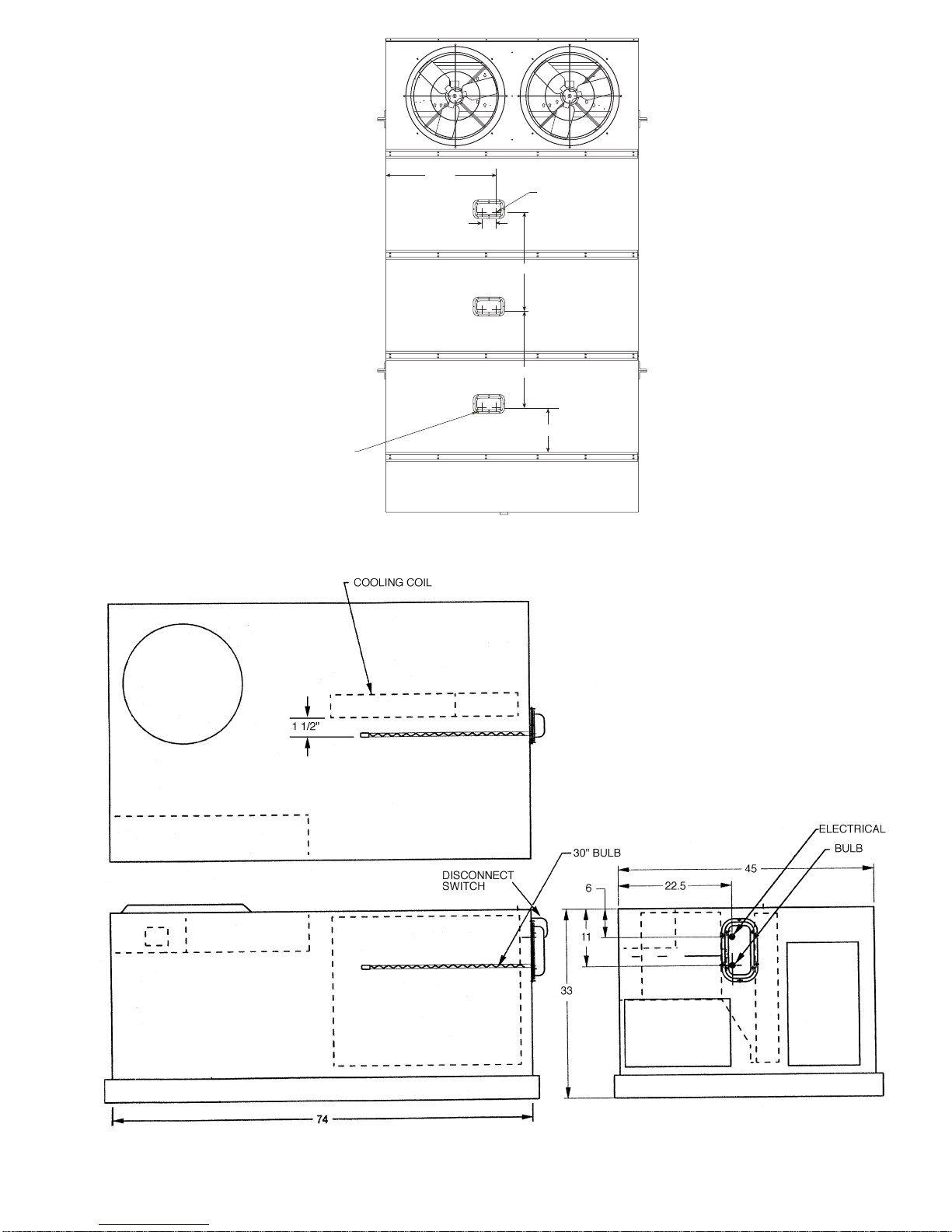
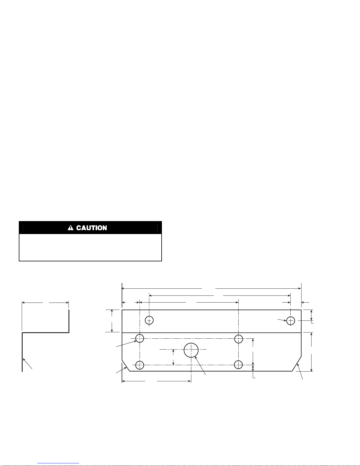
Size 008-014 Units:
A mounting bracket is not required. Disconnect switch
mounts directly onto the unit. See Fig. 15 and 16 for
location of disconnect switch on size 008-014 units.
Drill 0.875-in. hole in side of unit for wiring to discon-
nect switch. See Fig. 16 for wiring hole location.
Match up wiring hole in disconnect switch with wiring
hole drilled into side of unit. Mount disconnect switch
to unit with 4 self-tapping screws (field-provided).
Seal disconnect switch housing with RTV sealant to
prevent rain water from being drawn into the unit.
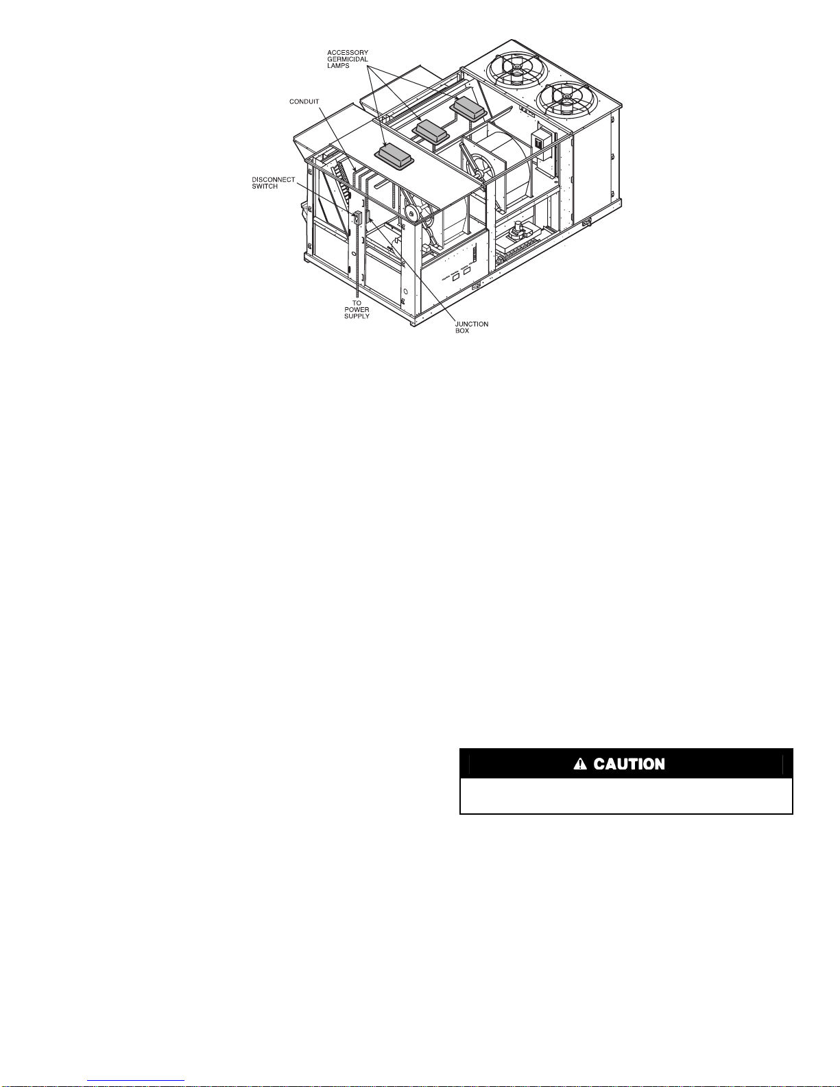
5. A separate source power supply must be routed to the
accessory germicidal lamp’s unit mounted disconnect
switch per applicable codes. Unit wiring and control
box connections should not be used. Refer to the Pack-
age Usage table for electrical characteristics of power
supply. Power source must be a suitable fused,
grounded, protected source with the correct voltage.
Other voltages will permanently damage the germi-
cidal lamp.
Wire per Table 1.
6. Any hinged potential access panel or door to the instal-
lation area must be interlocked with the accessory
power source to turn the lamp off if the door is opened.
Access doors should be labelled with appropriate
warnings about exposure to ultra-violet light.
A pushbutton door interlock switch (Carrier Part No.
HR54ZA101) is required on all hinged access panels.
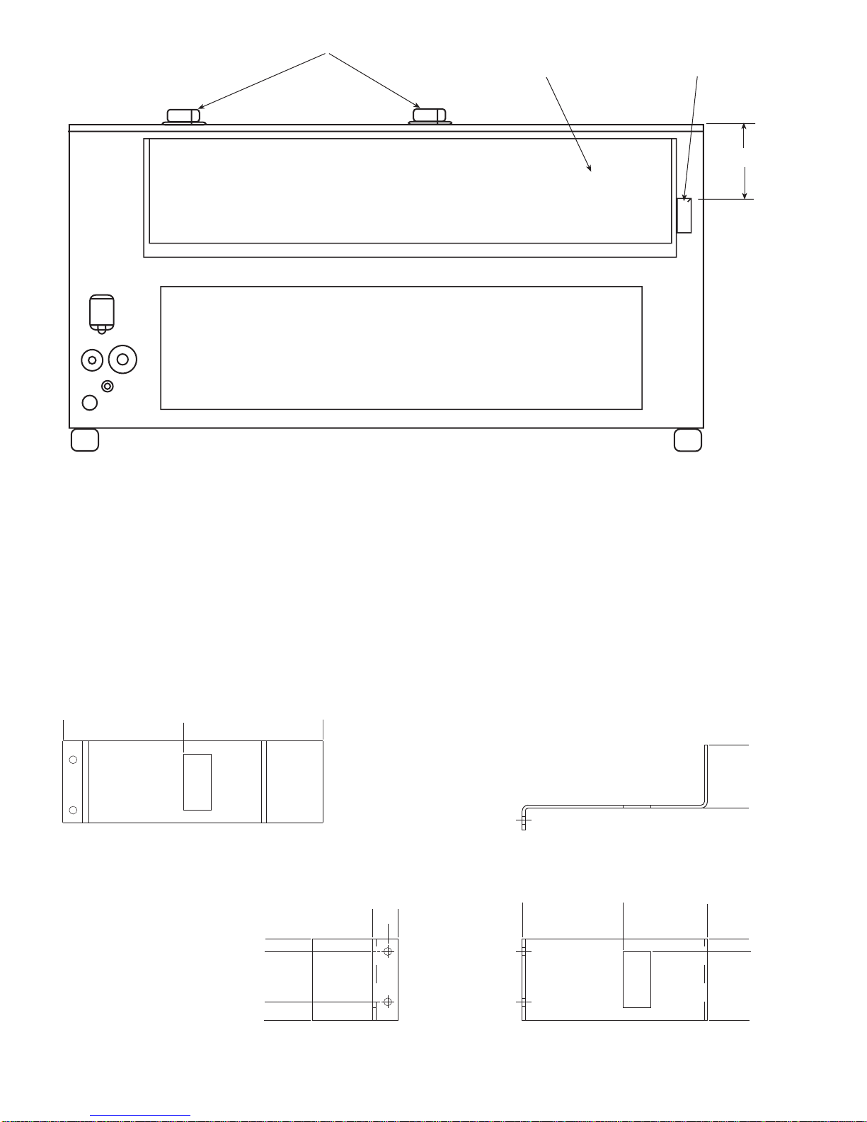
Use a field-fabricated and -installed bracket to mount
the door interlock switch. See Fig. 17 and 18. Drill
0.406-in. hole in unit z-flange 1.75-in. from end of
door for pushbutton of interlock switch. Push button
will go through unit z-flange and will be contacted by
door. See Fig. 15.
Use insulated sleeve terminals for connection to inter-
lock switch. The pushbutton door interlock switch is
not required on non-hinged access panels. Door inter-
lock switch should be located on the side of the access
door that opens. Locate the switch near the top of the
door so it will not be in a location where it interferes
with maintenance or service.
Run wiring into disconnect switch. Door interlock
switch should be wired into the power (Black) lead,
between the disconnect switch and the germicidal
lamp, to break power to the accessory when the door is
opened.
7. Using the accessory as a template, mark two 1-in.
insertion holes on the mounting surface. Mark 8 holes
for accessory mounting. See Fig. 3 and 4 for location.
The 1-in. holes are used for electrical connections and
the germicidal bulb. See Fig. 5.
8. Drill 1-in. holes in unit where marked.
9. Use field-supplied No. 10 self-drilling screws to attach
accessory to unit.
NOTE: Holes can be drilled in unit if self-drilling
screws are not used. Drill 8 holes for eight no. 10
screws used to attach accessory to unit. Using eight no.
10 screws provided, attach accessory to unit.
Be sure accessory has a watertight seal against unit
wall. Use standard 1/2-in. strain relief connectors
when running wiring through any hole in unit.
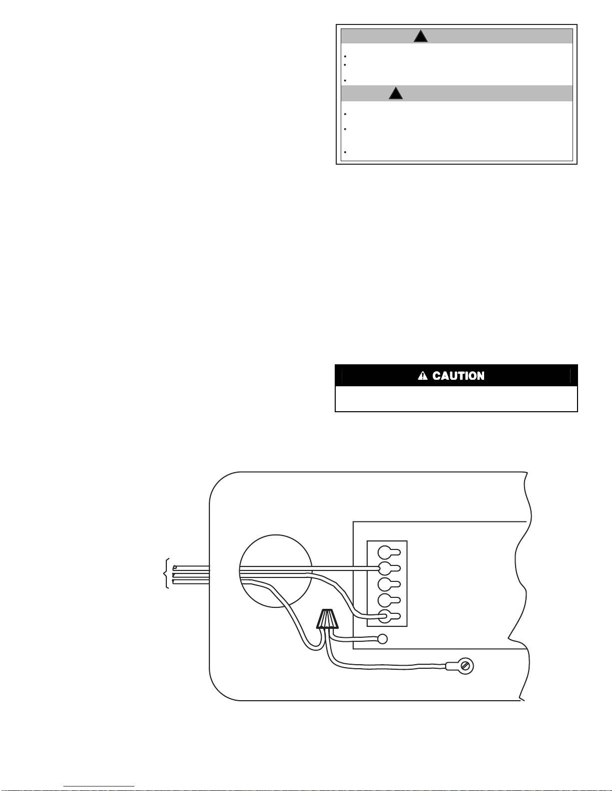
10. Wire accessory germicidal lamp to disconnect switch.
See Table 1 for wiring recommendations. Use UVC
resistant wire, outdoor duty, 14-gage ROMEX cable or
1/2-in. conduit for all wiring. Wire power, neutral, and
ground leads to disconnect switch. Do not ground to
unit. Ultra-violet lamps should be operated continu-
ously from power source. Lamps should not be con-
nected to indoor fan power source or any power source
where they would be cycled more than twice per day.
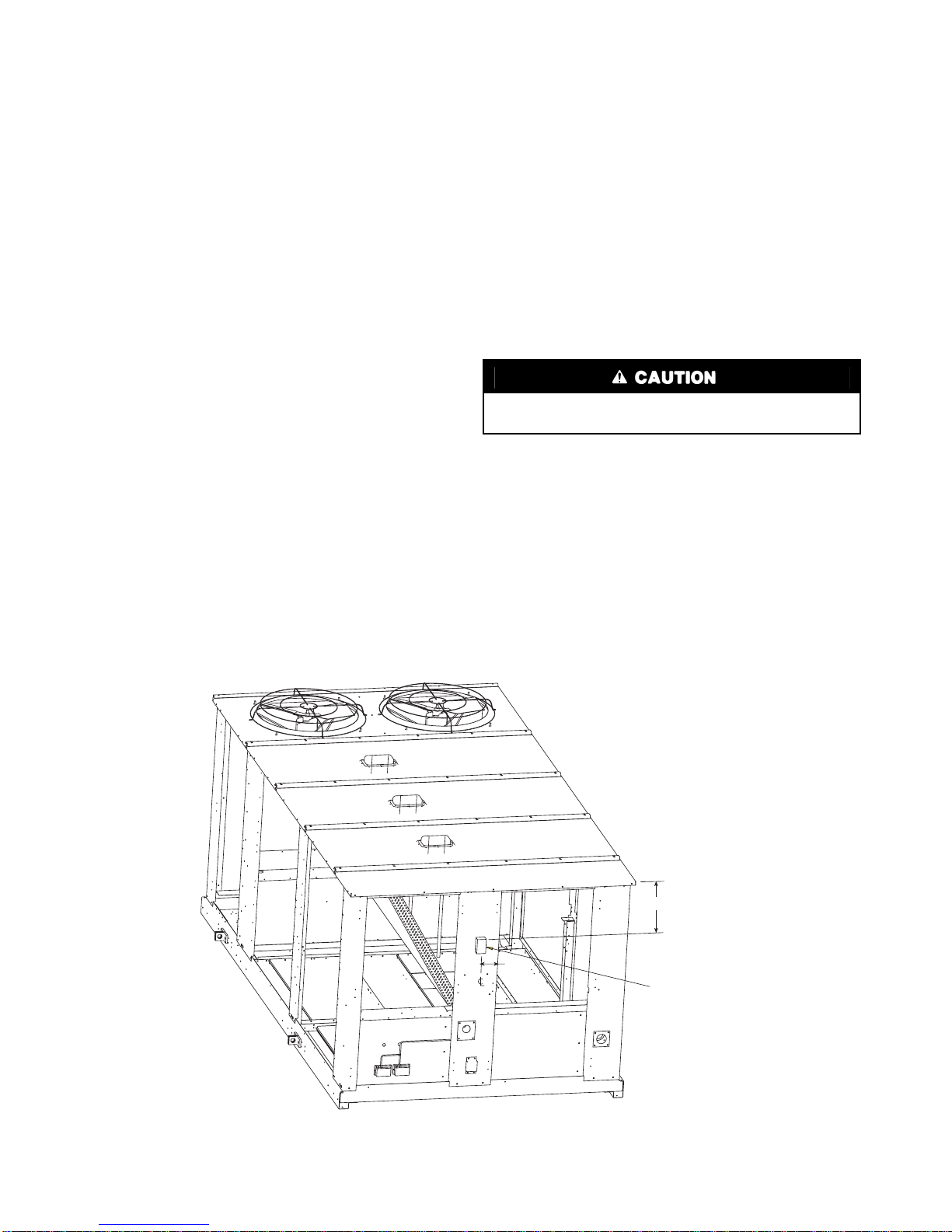
Be careful not to drill into coil, refrigerant lines, or other
objects inside the HVAC unit. Damage to unit can result.
Fig. 12 — Junction Box Installation — 48/50EJ,EK,EW,EY Units (48EJ024 Shown)