Carrier AQUASMART User manual

42GW
42WH
42Y
42JW - 42EL
001
•
L
L
O
Y
D
'
S
R
E
G
I
S
T
E
R
Q
U
A
L
I
T
Y
A
S
S
U
R
A
N
C
E
I
S
O
9
0
0
1
AQUASMART
Room Controller
INSTALLATION MANUAL

AQUASMART Room Controller
GB - 1
Installation manual
ENGLISH
This control system only operates with water indoor units of the following type:
42GW Cassette, 42WHC/WHE Hi-Wall, 42Y Fan coil, 42JW“Satellite”and 42EL “Aqualia”.
For installation instructions of this unit, refer to the relevant manuals.
Contents Page
General information .................................................................................................................... 2
Choosing the installation site...................................................................................................... 2
Installation .................................................................................................................................. 3
Electrical connections................................................................................................................. 4
Room controller configuration ................................................................................................. 5/7
Troubleshooting.......................................................................................................................... 7
INSTALLATION FLOW CHART
Read manual
Install
Room Controller
Wire Room Controller
and unit network
Configure
Room Controller
Test System
Operate
Room Controller
Dimension (mm)
108
70
20

GB - 2
AQUASMART Room Controller
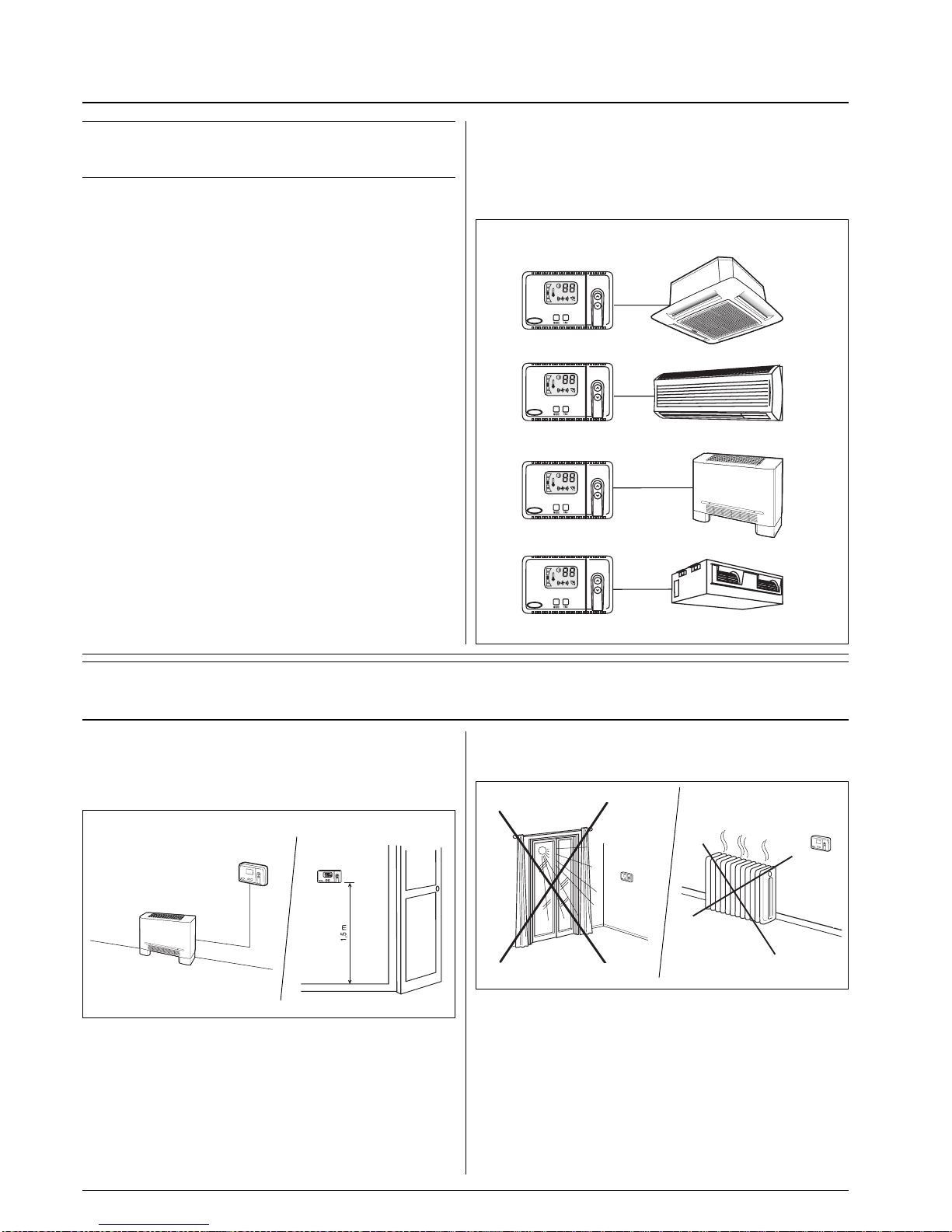
The Room Controller Location
The Room Controller can be positioned on the unit or fitted to
the wall.
If fitted to a wall, the Room Controller must be mounted:
•In the same area where the unit is located, preferably on an
inside partitioning wall.
•Approximately 1.5 m from floor.
•On a section of wall without pipes or duct work.
General information and choosing the installation site
IMPORTANT:
Read the entire instruction manual before starting the
installation.
•For trouble-free installation, which should be carried out by a
qualified installer, follow the installation chart sequence.
•Follow all current national safety code requirements. In particular
ensure that a properly sized and connected ground wire is in place.
•After installation thoroughly test the system operation and
explain all system functions to the owner.
•Leave this manual with the owner for consultation during
future periodic maintenance.
•Dispose of packaging material in accordance with local
requirements.
•The manufacturer denies any responsibility and warranty shall
be void if these installation instructions are not observed.
•Inspect equipment for damage due to improper transportation or
handling: file an immediate claim with the shipping company.
Do not install or use damaged units.
•In case of any malfunctioning turn the unit off, disconnect the
mains power supply and contact a qualified service engineer.
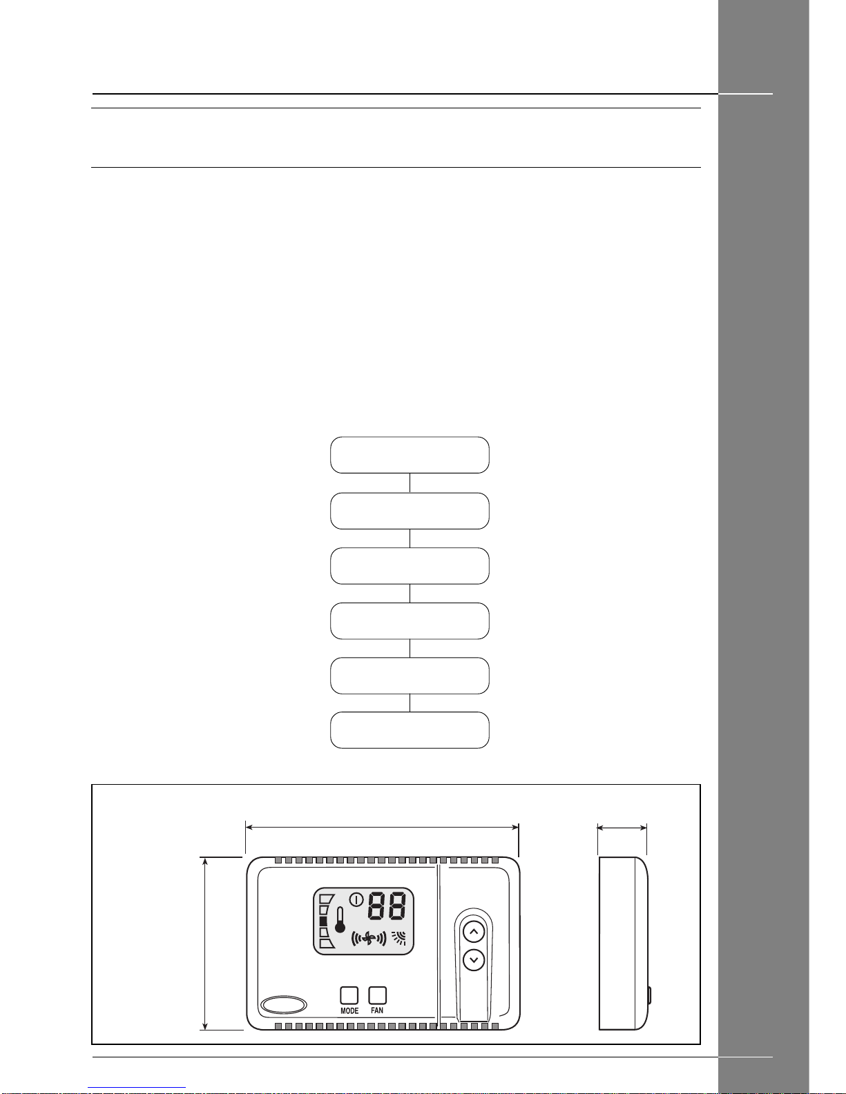
Models
Products that the Room Controller can interface with
42GW CASSETTE
42WHC/WHE HI-WALL
42Y FAN COIL
42JW SATELLITE
42EL AQUALIA
Room Controller
Power
Note that the Room Controller requires no batteries and is not
“power stealing”. It requires 12 VDC to be connected for
proper operation, which is easily obtained from the Unit
connected to it.
The Room Controller will not operate without this connection.
If the indoor air sensor on the Room Controller has been
selected, it should NOT be mounted:
•Close to a window, on an outside wall, or next to a door
leading to the outside.
•Exposed to direct light and heat from a lamp, sun, fireplace,
or other temperature-radiating object which may cause a false
reading.
•Close to or in direct airflow of a heating or cooling supply.
•In areas with poor air circulation, such as behind a door or in
an alcove.
•Maximum of 150 m of total network wiring.
Choosing the installation site and installation
Minimum clearances

GB - 3
AQUASMART Room Controller
ENGLISH
•Match and connect equipment wires to proper terminals in the
connector block.
Both power and communication wires must be connected
correctly for proper Room Controller operation.
•Push any excess wire into the wall and against mounting
base.
If the air sensor is being used on the Room Controller, seal
hole in wall to prevent air leaks.
Leaks can affect sensor operation.
•Push the Room Controller snap hinge to the base.
Mounting
WARNING:
Before installing the Room Controller, turn off all power to
the Unit that will supply power to the Room Controller.
Electrical shock can cause personal injury or death.
• Turn OFF all power to unit.
•Open the Room Controller rear mounting base to expose
mounting holes.
The base can be removed to simplify mounting (snap apart
carefully at hinge to separate mounting base from remainder
of the Room Controller).
•Route the Room Controller wires through the large hole in
the mounting base.
Level mounting base against wall (for aesthetic value only the
Room Controller need not be level for proper operation) and
mark the wall through the 2 mounting holes.
•Drill two 5 mm mounting holes in wall where marked.
•Secure mounting base correctly ( ) to wall with 2 screws
and anchors provided, (additional anchoring holes available
for more secure mounting if needed) making sure all wires
extend through hole in mounting base.
•Adjust length and routing of each wire to reach the proper
terminal in the connector block on the mounting base, with 6
mm of extra wire (strip only 6 mm of insulation from each wire
to prevent adjacent wires from shorting together when
connected).
Installation
햲Mounting screws
햴To indoor unit
햵Rigid PVC
conduit inside
ø30mm min.
햶Plaster approx
30 mm
햷Room
Controller
햸Connector
block
햳Connection cable
햳Connection cable
햴
햵
햶
햷햸
G
P
C
햳
G
P
C
햳
G
P
C

GB - 4
AQUASMART Room Controller
Electrical connections
Wiring Room Controller to the unit
WARNING:
Before connecting any wiring to the Room Controller,
turn off all power to the unit that will supply power to the
Room Controller.
Electrical shock can cause personal injury or death.
The Room Controller is connected to the unit using the
following instructions.
Reference Diagram 1 or 2 when making these connections.
Power cable and communication connections Room
controller to the unit (3 conductor cable).
•Slacken the terminal screws P (DC Power), G (GROUND) and
C (SIGNAL), present on the rear base of the Room Controller.
- P (DC power)
- G (Ground)
- C (Signal)
•Make the connections on the terminal block of the Room
Controller as per diagram 1.
•Connect the other end of the cables to the terminal block of
the unit as per diagram 1.
•Power cable installation is now complete.
•Slacken the terminal screws P (DC Power), G (GROUND)
and C (SIGNAL), present on the rear base of the Room
Controller.
- P (DC power)
- G (Ground)
- C (Signal)
•Make the connections on the terminal block of the Room
Controller as per diagram 2.
•Connect the other end of the cables to the terminal block of
the unit as per diagram 2.
•Power cable installation is now complete.
Wiring Materials required
(supplied by installer)
•1 small screwdriver
•3 x 0,5 mm2multiple cables, double insulated.
Suggested type: H03VV-F.
Diagram 2:
Connection diagram for the 42Y unit
Wire colours
ABrown
BBlue
Y/G Yellow/green
쐃Room Controller
쐇Unit
햴Terminal block in the Room Controller
햵Terminal block in the unit
햶Window contact (if present)
햷Local Bus; maximum 6 units
Diagram 1:
Connection diagram for the following units:
42GW
42WHC/WHE
42JW
42EL
쐃
쐇햴
D.C. POWER
GROUND
(SIGNAL)
P
G
C
7
6
5
4
3
2
1
햷
햵
햶
A
B
Y/G
A
B
Y/G
쐃
쐇햴
D.C. POWER
GROUND
(SIGNAL)
P
G
C
5
4
3
2
1
햷
햵
햶
A
B
Y/G
A
B
Y/G
Wire colours
ABrown
BBlue
Y/G Yellow/green
쐃Room Controller
쐇Unit
햴Terminal block in the Room Controller
햵Terminal block in the unit
햶Window contact (if present)
햷Local Bus; maximum 6 units

GB - 5
AQUASMART Room Controller
ENGLISH
Access to the configuration menu
Press and hold down the “MODE”button for around 5 seconds
until “1-”appears on the display..
This indicates that the user could set configuration item
number 1.
1- FAHRENHEIT OR CELSIUS: SELECTION
Select between Fahrenheit (F) or Celsius (C) operation.
Factory default is Celsius.
To select while in configuration mode:
•The Configuration Option (“1-”) and the current selection
should be displayed.
•Press the “MODE”button to alter the current selection.
•Use either the “UP”or “DOWN”button to change between “F”or “C”.
•To end configuration do not press any buttons for 10 seconds.
To move to the next setting, press the “UP”button again and the
“2-”will be displayed.
Press the “DOWN”button and the display will change to “1-”.
up
down
up
down
2- AIR SENSOR SELECTION
Program if you want to use the air temperature sensor
present in the Room Controller “On”or the one present in the
units “OF”.
The default setting is OF.
To select while in configuration mode:
•Press “UP”botton until “2-”is displayed.
•Press the “MODE”button to change the current selection
•Use either the “UP”o “DOWN”to change between “OF”(OFF)
and “On”(ON).
•To end configuration do not press any buttons for 10 seconds.
3- UNITTYPE
It allows to determine appropriately which unit type is
connected to the Room Controller.
To select while in “UNIT CONFIGURATION”mode:
•Press and hold down the “UP”and “DOWN”keys at the same
time for around 5 seconds, until “-2”appears on the display.
•Press “MODE”button to alter the current selection (the “-”will
disappear).
up
down
up
down
Room Controller configuration
up
down

GB - 6
AQUASMART Room Controller
Room Controller configuration
•Press either the “UP”or “DOWN”button until the appropriate
number is displayed. Please refer to the following table for
proper selection:
Unit type Application Size Selected
value
Hi-Wall 42WHC/WHE
All All 1
Cassette 42GW All All 3
Fan Coil 42Y Vertical All 4
Fan Coil 42Y Horizontal All 5
Above ceiling 42JW All All 5
Above ceiling 42EL All All 5
If your unit is not included in the above models, refer to unit
installation manual to determine the selected value.
An error in the selected value, causes a malfunction or
absent swing of the louver and a bad comfort in the
heating mode.
•To end “UNIT CONFIGURATION”mode do not press any buttons for
10 seconds.
4- WINDOW CONTACT SELECTION
It is possible to configure the window contact in the NO
condition (normally open) or in the NC (normally closed)
condition.
To perform this configuration, proceed as follows:
•Press and hold down the “UP”and “DOWN”keys at the same
time for around 5 seconds.
•Press “UP”button until “-4”is displayed.
•Press the “MODE”button to select the mode.
up
down
up
down
up
down
•Press the “UP”or “DOWN”per passare dalla modalitàbutton to
go from the “O”mode (open) to the “C”mode (closed).
•To end configuration do not press any buttons for 10 seconds.
5- BOOSTER HEATING SELECTION
(supplementary heating)
Units fitted with electric heaters can be enabled for the
“Booster Heating”function (supplementary heating)
This function permits heating using hot water and the electric
heaters at the same time.
To perform the configuration proceed as follows:
•Press and hold down the “UP”and “DOWN”keys at the same
time for around 5 seconds.
•Press “UP”button until “-5”is displayed.
•Press the “MODE”button to select the mode.
•Press the “UP”or “DOWN”button to go from the “OFF”mode
(Booster Heating not enabled) to the “ON”mode (Booster
Heating enabled).
•To end configuration do not press any buttons for 10 seconds.
up
down
up
down
up
down
up
down

GB - 7
AQUASMART Room Controller
ENGLISH
6-SELECTINGTHETYPE OF APPLICATION
(2 Pipes / 4 Pipes)
With this selection we choose the type of application:
2 Pipes The unit is equipped with just one valve which heats
(winter) when supplied with hot water and cools
(summer) when supplied with cold water.
4 Pipes The unit is equipped with two valves (hot water valve
and a cold water valve).
To make the configuration, proceed as follows:
•Press and hold down the “UP”and “DOWN”keys at the same
time for around 5 seconds.
•Press “UP”button until “-6”is displayed.
up
down
up
down
Room Controller configuration,troubleshooting
•Press the “MODE”button to select the mode.
•Press the “UP”or “DOWN”button to go from the “P2”(2 pipes)
mode to the “P4”(4 pipes) mode.
•To end configuration do not press any buttons for 10 seconds.
up
down
Troubleshooting
+12 volts applied
to Room
Controller at the
correct terminals
and still does not
operate
Symptom Possible Cause Things to check Solution
No LCD display 1) mis-wiring of the 12 volt
power to Room Controller control.
2) Power not online
3) No 12 volts between P
and G of terminal block.
1)The Room Controller
is damaged.
1) Verify that +12V and Ground are connected to the
proper terrminals of the Controller.
Reference Installation wiring section for correct
connections
1) Check that the units main power is connected. The
main control board should be operating normally
1) Check the installation of the J6 plug on the main
control board.
After disconnecting the power,
correct the wiring problem and
re-cycle power.
After verifing the wiring to the
Room Controllerl, re-cycle the
unit power.
After disconnecting the power,
correct the wiring problem and
re-cycle power.
Change the Room Controller
and re-cycle power.

L010123H56 - 0901
Via R. Sanzio, 9 - 20058 Villasanta (MI) Italy - Tel. 039/3636.1
The manufacturer reserves the right to change any product specifications without notice.
Order No. 16005-74, September 2001. Supersedes Order No. 16005-74, May 2001. Printed in Italy
Other manuals for AQUASMART
1
Table of contents
Other Carrier Temperature Controllers manuals

Carrier
Carrier NSB-10K-2-O-BB2 Owner's manual

Carrier
Carrier EQT1-4 User manual

Carrier
Carrier Atmosphera 42EM series Manual

Carrier
Carrier Room Controller User manual

Carrier
Carrier ComfortChoice EDGE Instructions and recipes

Carrier
Carrier NSB-10K-2-I-2-BB2 Owner's manual

Carrier
Carrier Infinity SYSTXCCUIZ01 Instructions and recipes

Carrier
Carrier ZS Standard User manual

Carrier
Carrier T-55 User manual

Carrier
Carrier Sensitech TempTale GEO Ultra User manual