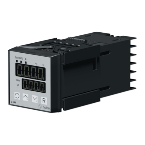
hotset hotcontrol cDT+ User manual

Rev. 1.00.05
11/2017
Start-up-, Service- and Operation
Manual
Translation of original manual
Start-up-, Service- and Operation
hotcontrol cDT+


1
Start-up-, Service- and Operation Manual hotcontrol cDT+
Rev. 1.00.05
Subject to technical changes
hotcontrol cDT+ 5
Typographical Conventions 6
Additional and continuative documents 7
Product safety and quality certification 7
Security References 8
Security References for User 8
Intended use 9
Maintenance 9
Warranty Conditions 10
Transport and Storage 10
Transport 10
Unpacking 10
Storage 10
Lift and carry 10
Disposal 10
Immediately after Switch ON 11
hotcontrol cDT+ starts 12
Dialog box for switch-on of hot runner controller 13
Operation by Control&User Interface - general specification 14
Control&User Interface CUI07 Operation (gestures) 15
Current view 16
Messages, Symbols in Header 17
Alarm key 18
Function keys 18
Show views 19
Main keys 20
Color of key 20
Scroll 20
Pinyin 21
Main keys 22
Heating ON/OFF 22
Boost 24
Standby 26
Login/Logout 27
Standard Operation 29
Change of setpoint value / Change of parameters 30
Change output value / Activate manual mode 31
Views 33
Standard view 34
Zoom level 35
Colour coding for zone 36

2
Rev. 1.00.05
Subject to technical changes
Group view 37
Table view 38
View All 39
MoldCheck view 40
View Alarm 41
Trend view 42
Trend settings 43
Input dialog zones 46
Parameter list [A] 47
Parameter-Field [B] 48
Numeric keypad [C] 49
Zone selection keys [D] 50
Edit group 52
Copy parameters from one zone to another 55
DIRECT zone selection [E] 58
Zone Selection Overview [F] 60
Function keys 61
Program 61
Allocation of program and tool coding 65
MoldSnapshot 67
Activate current transfer 70
Alarms 71
Messages - Alarms, Status, Functions 73
Alarms 74
Status 75
Functions 76
Trouble Shooting 77
Sensor break TCb 78
Sensor incorrect polarity TCp 78
Sensor alarm TCs 79
Potential error Pot 79
Current tolerance error 80
Thyristor alarm Thy 80
Residual current RC 81
Current alarm Cur 81
Total breakdown of heater HBr 82
Temperature outside limit value range 82
Temperature alarm Tmp 83
Fuse failure Fus 83
Phase missing FUS 83
Heater alarm HST 84
Channel data error Cha. 85
Channel data error card Cha 85
System data error SYS. 85
System data error card SYS 86
Message CAN 86
Message CAN - Change in system configuration 86
Message CAN - Failure of HTC-Card 86
Message CAN. - No more actual values 87
Message CANID - Same NodeID 87
Status indication on HTC-Card 88

3
Start-up-, Service- and Operation Manual hotcontrol cDT+
Rev. 1.00.05
Subject to technical changes
Infocenter 89
System settings 90
Change temperature unit 90
Key arrangement 92
Ampere / Watt 94
Activate current transfer 96
System parameters 98
Communication 99
User Administration 101
Change password 105
Generate USB key 107
Configure table view 109
Software Download Slave 112
Hardware Setup 116
Scan 117
Read software version 118
Load factory setting 119
Fan test 120
Language 121
Date / Time 123
Inputs / Outputs 125
Start learning phase of process monitoring 129
Cleaning 129
Product information / Status Info Process & Hot runner controller 131
Messages 132
Possible messages 133
Pairing Mode 135
Functions 138
Heating current measuring - and - monitoring 138
Automatic ramp 139
Heat'n'Dry 141
Auto Tuning (Identification) 142
Start-up mode 143
Leading zone operation 143
Auto Standby 144
Hot Runner Controller overall functions 146
Reset password 147
USB support 148
Relay heating 149
MoldCheck 150
MoldCheck Trouble Shooting 157
Process Monitoring 160
Process Monitoring Mode: Intelligent 163
Process Monitoring Mode: Fully automatic 166
Process Monitoring Mode: Manual 168
Process monitoring at a glance 171
Update-Process 172
Update Firmware CUI07 172
Update language-file 175
Technical Data 177
hotcontrol cDT+ 178

4
Rev. 1.00.05
Subject to technical changes
System Configuration 179
Rear side Hot Runner Controller - Connections 179
Interfaces and Digital inputs 181
Interface XS1 RS485 181
Interface XS2 CAN 181
Digital inputs XM3 DIO 182
Interface XS3 RJ45 182
Interface XS5 20 mA (Option) 183
Interface XS7 external operation (Option) 183
Alarm Output XM1 Signal Plug 184
Control fuse 184
Sensor inputs and power outputs (Output plug XA*) 185
Power Supply 185
Replacement of single components 186
HTC 06/15 Heating Thermocouple Card - Replace fuses 187
HTC 06/15 Replace Heating Thermocouple Card 189
Replace Control&User Interface CUI07 190
Delivery Status Standard 191
Parameters 191
System parameters 193
Communication parameter 194
Views 195
Functions 195
Info center 196
Appendix 197
Consumable and Spare Parts 197
Version History 198

Hotset GmbH 5
Start-up-, Service- and Operation Manual hotcontrol cDT+
Rev. 1.00.05
Subject to technical changes
1 hotcontrol cDT+
Benefits at a glance
Little space requirement.
Extended range of function - Innovative functions such as Smart Power Limitation SPL and the further develop-
ment of well-known functions, contributing towards process security.
Number of zones can be expanded very quickly and easily by Pairing Mode.
Easy to maintain. Backup exchange or card exchange are not a problem. You only need to release the door,
open it, and you have access to the controller cards. hotcontrol cDT+ is also optionally available with external
fuses.
App for remote control via your Smartphone. Comfortable monitoring and diagnostics.
Hot runner controller with output limitation and intelligent output distribution
The equal control pulse distribution, Smart Peak Reduction SPR, reduces peak loads.
Ultra fast and reaction-free current measurement.
Data exchange, data backup, import and export of tool settings... everything is conveniently possible using the
USB port on the front.
Automatically recognizes new cards.
Available data interfaces and protocols allow connectivity to machine control, process control systems, process
data detection systems or established process optimization systems.

6Chapter 2
Typographical Conventions
Rev. 1.00.05
Subject to technical changes
2 Typographical Conventions
Symbols and conventions are used in this document for faster orientation for you.
Symbols
Caution With this symbol, references and information are displayed which are decisive
for the operation of the device. In case of non-compliance with or inaccurate
compliance there can result damage to the device or injuries to persons.
Note The symbol refers to additional information and declarations, which serve for
improved understanding.
Example With the symbol, a function is explained by means of an example.
Reference With this symbol, information in another document is referred to.
FAQ Here FAQ (Frequently Asked Questions) are answered.
To use ... specifies which materials, components etc. are to be used.
Installation ... indicates how the installationshouldtakeplace,forexample,order,arrange-
ment, etc.
Cross references are marked with this character. In the pdf version of the doc-
ument the objective of the cross reference is reached via the link.
Equations Calculation specifications and examples are represented in this way.
<View> Menu points (e.g. view) are represented in this way.
|Project| Windows (e.g. project) are represented in this way.
n.a. Not applicable, not existing
Warning, Possibility of
electric shock
General warning
sign
In all cases where the adjacent symbol is to see, the start-up, service and op-
eration manual must be consulted.

Hotset GmbH 7
Start-up-, Service- and Operation Manual hotcontrol cDT+
Rev. 1.00.05
Subject to technical changes
2.1 Additional and continuative documents
2.2 Product safety and quality certification
Data sheet hotcontrol cDT+
Start-up
Service
Operation
Information on this topic see document
hotcontrol cDT+ Start-up-, Service- and Operation Manual
Parameters Information on this topic see document
Manual hotcontrol cDT+ Parameters
Protocol PSG II InformationonthistopicseeprotocoldescriptionPSG IIandthecorresponding
object lists
Protocol Modbus Information on this topic see protocol description Modbus and the correspond-
ing object lists
Protocol Modbus/
TCP Information on this topic see protocol description Modbus/TCP and the corre-
sponding object lists
Protocol CANopen Information on this topic see corresponding object lists CAN
Firmware, language files
All available by Internet see www.hotset.com
CE marking

8Chapter 3
Security References
Rev. 1.00.05
Subject to technical changes
3 Security References
For the hot runner controller hotcontrol cDT+ hereinafter referred to as device (consisting of see Technical Data
(page 177)), the following safety instructions must be observed.
3.1 Security References for User
All persons, responsible for the mounting/start-up/operation/maintenance/servicing of the device, have to
be skilled appropriately
consider this start-up, service and operation manual exactly
regard this start-up, service and operation manual as part of the product
keep this start-up, service and operation manual during lifetime of the product
pass this start-up, service and operation manual to all successive owners or operators of the product
make sure, that every obtained amendment is integrated in this start-up, service and operation manual.
Please note the following safety instructions necessarily for protection against electric shock, risks of injuries and
fire.
At start-up, adhere strictly to the local safety regulations as well as the safety instruction.
Consider the regulations for prevention of industrial accidents for electrical installations and equipment by govern-
ment safety organization in industrial facilities.
Do not throw packaging material careless away, thermoplastic foil/ styrofoam parts etc. may get dangerous for
persons.
Protect device against moisture. Do not use in areas with high humidity.
Check, that the specified voltage on the type plate is identical with the mains voltage on-site.
Ensurethatthepowercordand the connecting cables arenotdamagedbyoverrun,squeezing,tearing or suchlike.
Protect the cords/cables against oil, sharp edges and temperatures above 70 °C.
Do not touch the mains plug with wet hands.
Lock the connected counter plug on the rear side of the device with retaining brackets against accidental removal.
Connect the connecting cable only in de-energized status.
Place the connecting cable to prevent stumbling.
Assure yourself that the e.g. connected injection mold is linked to the protective conductor.
Do not place any tanks, filled with liquid, on the top of the device, otherwise a dangerous situation may emerge.
The device is set up so that the main switch is easily accessible so that in emergency, the machine can be shut
down quickly.
Before installation, handling or operation of the device, please read through this start-up, ser-
vice and operation manual completely and carefully.

Hotset GmbH 9
Start-up-, Service- and Operation Manual hotcontrol cDT+
Rev. 1.00.05 Subject to technical changes
The feet of the device may not be removed. Also, make sure that there is on the right and left side of the housing
sufficient distance (desktop housing at least 5 cm ) so that the waste heat can escape. Around the bottom and
below the bottom of the device, the air is drawn to cool the heat sink. This area must be kept clear that the air can
be drawn in unhindered.
Work like e.g. maintenance and repair may be carried out by authorized and skilled qualified personnel only. Only
qualified personnel, skilled and on the risks trained, may use the device. The relevant accidental regulations as
well as other general approved safety-relevant, occupational-medical norms have to be obeyed. Unauthorized
modifications of the device exclude liability of the manufacturer/supplier for resultant damages.
Before working on this device always switch-off the mains switch and make sure that the device is de-energized.
Protect the supply voltage against unintentional reclosing.
For person and property damages, resulting of not considering this Start-up, service and operation manual or not
considering these safety instruction, warranty claim terminates. For these damages the manufacturer assumes no
liability.
3.2 Intended use
The hot runner controller hotcontrol cDT+ is exclusively designed for temperature-dependent control of electric
heaters (e.g. injection molds) determined within the specifications. More specific descriptions are given in this op-
erating instructions.
For the parameterization of customer desired functions, the customer is responsible.
Uses other than the above shall be improper and exclude the liability of the manufacturer/supplier for any related
persons -, property - and consequential damage.
3.3 Maintenance
A further maintenance is not necessary. Maintain a clean surface of the operating unit. For cleaning use a damp
cloth. Avoid the use of solvents, cleansers and abrasives.
Warning, Possibility of
electric shock
General warning
sign
In all cases where the adjacent symbol is to see on the device, note the safety
instructions necessarily on the hot runner controller hotcontrol cDT+ identi-
fied by this symbol/sign/label.
In all cases this Start-up-, Service- and Operation Manual must be consulted.
When properly used, the safety of the user and the device is guaranteed. The device may only
be used for the particular purpose.
With improper use the protection to persons and property may be impaired, and is thus no lon-
ger given.
Check regularly that the ventilation holes, located at the bottom of the device, are free of dust.

10 Chapter 3
Security References
Rev. 1.00.05
Subject to technical changes
3.4 Warranty Conditions
This product is subject to the legal warranty time periods for faults or deficiencies in manufacture.
Content of Warranty
If a malfunction relatively occurs through the manufacture, the manufacturer/supplier repairs or replaces the non-
conforming product, according to their own discretion.
The following repairs do not fall under the warranty and are liable to costs:
Malfunctions after the legal notice periods have expired.
Malfunctions caused through operating error and/or incorrect parameterization of the user (if the device is not
operated as described in the start-up, service and operation manual).
Malfunctions caused through other devices.
Changes or damage to the device which do not originate from the manufacturer/supplier.
If you wish to use services within the framework of this guarantee, please refer to the manufacturer/supplier.
3.5 Transport and Storage
3.5.1 Transport
The hot runner controller hotcontrol cDT+ (all single components together) is packed in a stable shock proofed
carton. This assures sufficient protection in normal case.
3.5.2 Unpacking
Check the packaging and then the device for identifiable damage incurred during transit. If damage is identified,
then please get in touch with the transportation company.
3.5.3 Storage
If you shouldnot put the device into operationimmediately, store it protected against dirt andmoisture. Permissible
temperature -20…70°C, average permissible humidity < 95 % per year, no condensation.
3.6 Lift and carry
The desktop housing device is to be carried by the handles provided, which are mounted on the two side parts.
3.7 Disposal
A manufacturer within the meaning of ElektroG (Electrical and Electronic Equipment), which implements the Eu-
ropean WEEE directive 2002/96/EC in German law, is registered under number WEEE registration number DE
64958116 . The components of this device are considered here too.
To avoid damage, the hot runner controllers must be transported STANDING.
In the case of damage the device may not be brought into operation.

Hotset GmbH 11
Start-up-, Service- and Operation Manual hotcontrol cDT+
Rev. 1.00.05
Subject to technical changes
4 Immediately after Switch ON
Immediately after Switch ON the boot monitor is executed. The system starts up and gets analyzed.
Are any problems detected, the boot monitor gives information on trouble shooting.
The following messages are shown.
The first switch-on after leaving the factory asks for the language to use on the display (see chapter Language
(page 121)).
Is an USB stick, with hex-file on it, plugged in, the system runs directly after switch-on into see chapter Update-
Process (page 172). Otherwise the message occurs: No language file or firmware found on USB.
Note
Identified faults Reason Trouble Shooting
Font missing.
Please update firmware. The in the system used font was not
loaded, and/or causes problems.
Load current firmware for CUI07 from
homepage on USB stick and update firm-
ware (see chapter Update Firmware
CUI07 (page 172)).
No firmware found.
Please update firmware. No firmware was found.
Load current firmware for CUI07 from
homepage on USB stick and update firm-
ware (see chapter Update Firmware
CUI07 (page 172)).
The user language is not com-
patible to the firmware. Please
update the language.
The language file for the 3. language,
currently provided by hotcontrol
cDT+, does not fit any longer (e.g.
texts were added)
Load current firmware for CUI07 from
homepage on USB stick and update firm-
ware (see chapter Update language-
file (page 175)).
We continuously further develop and improve our products and make available online
updates for
CUI07 Control&User Interface 07
HTC 06/15 Heating Thermocouple Card
via Internet.
Call up homepage www.hotset.com and search there for the product. In the download
area you find the latest firmware.

12 Chapter 4
Immediately after Switch ON
Rev. 1.00.05
Subject to technical changes
4.1 hotcontrol cDT+ starts
After successful end of boot monitor, the display changes to Standard view
In the Standard view, the zones are represented with their important characteristics dependent on the zoom level.

Hotset GmbH 13
Start-up-, Service- and Operation Manual hotcontrol cDT+
Rev. 1.00.05
Subject to technical changes
4.1.1 Dialog box for switch-on of hot runner controller
Is the parameter [SP17]Query for MoldCheck start (page 193)=ON, a dialog box is shown after switch-on of the
hot runner controller (also after activation of the heating by key).
Selection
Switch-on; The heaters are switched-on without any further check
MoldCheck; call of function see chapter MoldCheck (page 150)
Quit; Quit this dialog and change to Standard view

14 Chapter 5
Operation by Control&User Interface - general specification
Rev. 1.00.05
Subject to technical changes
5 Operation by Control&User Interface - general specification
Overview of displays and operation elements for control&user interface CUI07 of hotcontrol cDT+ dependent on
basic display.
The displays/views and operation elements presented are exemplarily, because
settings by Infocenter (page 89) may have been modified compared to the standard delivery
other users (not admin) are logged in
other programs are active
other current views are shown
Whether and which keys and views are enabled for the user, see chapter User Ad-
ministration (page 101).
The shown examples are usually for user admin.
Current view (page 16)
Function keys (page 18)
Keys Show views (page 19) Main keys (page 20)
Alarm key (page 18)
Messages, Symbols in Header (page 17)
Views
Date / Time (page 123)
Program (page 61),
Tool Coding
Header
Operation
elements

Hotset GmbH 15
Start-up-, Service- and Operation Manual hotcontrol cDT+
Rev. 1.00.05
Subject to technical changes
5.1 Control&User Interface CUI07 Operation (gestures)
The Control&User Interface CUI07 of hotcontrol cDT+ is operated by Touch-Display.
Tap
Touch screen with your finger
The selected key changes colour
when the keystroke was accepted
as a command.
Wipe down
Wipe up
Touch screen with your finger, pull
in one direction and lift finger off
the screen
E.g. in header over screenedge to
display Infocenter (page 89)
Wipe left/right
Touch screen with your finger, pull
in one direction and lift finger off
the screen
E.g. in zone view, to show further
zones, when existing
Zoom IN
Zoom +
Two fingers are positioned on the
screen and moved apart (Pinch
open)
E.g. zone view for Zoom IN. Thus,
a small number of zones is dis-
played on the screen, but with
more details.
Zoom OUT
Zoom -
Two fingers are positioned on the
screen and moved toward each
other (Pinch open)
E.g. zone view for Zoom OUT.
Thus, a larger number of zones is
displayed on the screen, but with
less details.

16 Chapter 5
Operation by Control&User Interface - general specification
Rev. 1.00.05
Subject to technical changes
5.2 Current view
The current view is selected via key and the view name is displayed in the header .
Views; see chapter Show views (page 19)
The shown arrows indicate, that in the direction of the arrows is
more information available. Navigation by see chapter Con-
trol&User Interface CUI07 Operation (gestures) (page 15).
<current page> / <of maximum pages> <Name of view>.
1/3 Standard
2/3 Standard
3/3 Standard
Exemplary display

Hotset GmbH 17
Start-up-, Service- and Operation Manual hotcontrol cDT+
Rev. 1.00.05
Subject to technical changes
5.3 Messages, Symbols in Header
If at least one message is existing, this is indicated to the user in the header.
Display Infocenter by Wipe down
(page 15) in the header over screen
edge
The following symbols are additionally displayed in the header in the marked field on the left hand,
if CAN-connection between 2 cabinets
(see chapter Hot Runner Controller overall functions (page 146))
if hotcontrol cDT+ by CAN connected, zone numbers are overlap-
ping
(see chapter Hot Runner Controller overall functions (page 146))
if control is stopped, e.g. at Software Download Slave (page 112) or
if the system scans the HTC-cards.
if
input block is active;
e.g. if PC with installed own PC software (operation software
TEMPSoft2) and/or via bus connection to machine control is
connected.
if By this symbol is signalized, that (see chapter) Process
Monitoring (page 160) is activated. Activation of function by system
parameter [SP07]Process monitoring mode (page 193).
if
By this symbol is signalized, that (see chapter) Pairing Mode
(page 135) or interface serial/CAN is activated. Activation of
function Pairing Mode (page 135) by system parameter
[CP24]Pairing Mode (page 194).
if By this symbol is signalized, that (see chapter) Pairing Mode
(page 135) has detected a problem. Possible reasons see
Messages (page 132).

18 Chapter 5
Operation by Control&User Interface - general specification
Rev. 1.00.05
Subject to technical changes
5.4 Alarm key
Whether the key Alarm is activated for the user, see chapter User Administration (page 101).
5.5 Function keys
Whether and which keys are enabled for the user, see chapter User Administration (page 101)
No alarms By selection of the key, the alarm view is displayed (see chapter
Alarms (page 71)).
There are persistent alarms By selection of the key, the alarm view is displayed (see chapter
Alarms (page 71)).
Group Only if Group view was selected before, see chapter Show views
(page 19)
Program The name of the activated program is displayed in the header. See
chapter Program (page 61).
Is tool coding active in hotcontrol cDT+ ,the transferred tool coding
(e.g. 00000001) from the connected tool to hotcontrol cDT+ is vis-
ible in the header alternating with the name of the activated pro-
gram.
MoldSnapshot See ChapterMoldSnapshot (page 67)
Current transfer See ChapterActivate current transfer (page 96)
Table of contents
Other hotset Temperature Controllers manuals
Popular Temperature Controllers manuals by other brands

Victron energy
Victron energy CAN-bus Temp sensor manual

Hakko Electronics
Hakko Electronics FG-100 Calibration instructions

eltherm
eltherm ELTC/L-15 Operation manual

Azel
Azel DST-777 Series Installation and operating instructions

Define Instruments
Define Instruments PRO-TC-LV manual

STIEBEL ELTRON
STIEBEL ELTRON RTF-TC instructions

Jung
Jung KNX 5178TSM-01 Series operating instructions

Vaisala
Vaisala TempCast FMP102 Setup guide

Omron
Omron E5CD-B manual

Rheem
Rheem Raypack Temp-Tracker B-40 Installation & operating instructions

Pentair
Pentair Raychem RTD-200 installation instructions

OEG
OEG Como Operating and installation instructions