Carrier Touch Pilot 33CNTPILOT User manual

This document is the property of Carrier Corporation and is delivered on the express condition that it is not to be disclosed,
reproducedinwholeorinpart,orusedformanufacturebyanyoneotherthanCarrierCorporationwithoutitswrittenconsent,and
that no right is granted to disclose or so use any information contained in said document.
Carrierreservestherightto changeormodify theinformationor productdescribedwithout priornoticeand withoutincurringany
liability.
© 2006,CarrierCorporation 11-808-363-01 03/06
Touch Pilot™
Installation and Operation Instructions
Part Number 33CNTPILOT
Introduction ................................................................. 1
About this Manual .................................................. 1
Safety Considerations .................................................. 1
General ......................................................................... 1
Installation ................................................................... 1
Location................................................................... 1
Power Transformer Wiring ...................................... 1
Carrier Network Communication Bus Wiring ........... 1
Communication Bus Wire Specifications ....... 1
Connection to the Communication Bus .......... 1
Mounting ................................................................ 2
Surface Mount................................................ 2
Decorative Bezel ............................................. 2
Chiller Display Mounting ............................... 2
Operation...................................................................... 4
Power-Up Display.................................................... 4
Default Device Designation............................ 4
Default Group Designation............................. 4
Group Display Screen .............................................. 4
To Remove a Point from a Group Display....... 5
To Add a Point to a Group Display ................ 5
Navigation and Operation Pushbuttons.................. 5
BACK ............................................................. 5
HOME............................................................. 5
MAIN MENU ................................................. 5
PREVIOUS ...................................................... 5
NEXT .............................................................. 5
OK .................................................................. 5
NO .................................................................. 5
CANCEL ......................................................... 5
CLEAR DATA................................................ 5
RESET DATA................................................. 5
ADD ............................................................... 5
REMOVE ........................................................ 5
INC, DEC ........................................................ 5
SCROLL UP, DOWN ...................................... 5
PAGE UP,DOWN........................................... 5
FORCE ............................................................ 5
AUTO ............................................................. 5
MODIFY ......................................................... 5
ALARM INDICATOR LIGHT ........................ 5
START/STOP BUTTON ................................. 6
Main Menu.............................................................. 6
LOGIN ............................................................. 6
LOGOUT ......................................................... 6
SETUP ............................................................ 6
ATTACH ........................................................ 6
TIME .............................................................. 6
ALARMS ....................................................... 7
RESET ............................................................. 7
SCHED ............................................................ 7
STATUS, SETPNT, SERVICE, MAINT OR
CONFIG .......................................................... 7
Setup Menu Screen ................................................. 7
Configuration Tables ................................................... 8
User Configuration (USERCONF) Table.................. 8
BACKLIGHT ALWAYS ON? ......................... 8
FULL ACCESS PASSWORD .......................... 8
LIMITED ACCESS PASSWORD ................... 8
ACTIVE LANGUAGE PASSWORD ............... 8
ACTIVE LANGUAGE ..................................... 8
TIME FORMAT ............................................. 8
DATE FORMAT ............................................ 8
UNITS BASE .................................................. 8
CONTRAST CONTROL ................................. 9
NETWORK MODE ......................................... 9
ALARM ACKNOWLEDGER ......................... 9
BROADCAST ACKNOWLEDGER ................ 9
EQUIPMENT CCN ADDRESS .......................10
BUS NUMBER ...............................................10
ELEMENT NUMBER .....................................10
CONTROL VARIABLES ................................10
EQUIPMENT STATUS .................................10
EQUIPMENT START/STOP .........................10
ALARM STATUS .........................................10
ALARM RESET.............................................10

ii

1
INTRODUCTION
About this Manual – This manual provides instructions
for using the Touch Pilot as a Carrier communicating net-
work (CCN) user interface.
NOTE: All instructions in this manual assume that the Touch
Pilot is physically connected to the CCN Bus (versus di-
rectly to a chiller) and that the Display is in Network mode
operating as a CCN user interface, as specified using the
Main Menu's Setup option.
SAFETY CONSIDERATIONS
Air-conditioning equipment will provide safe and reliable
service when operated within design specifications. The
equipment should be operated and serviced only by autho-
rized personnel who have a thorough knowledge of system
operation, safety devices and emergency procedures.
Good judgement should be used in applying any
manufacturer’s instructions to avoid injury to personnel or
damage to equipment and property.
GENERAL
The Touch Pilot (33CNTPILOT) is a user interface for the
Carrier communicating network and serves as a user inter-
face and configuration tool for the AQUAFORCETM and other
chillers, a Carrier 3VTM zoning system, linkage-compatible
air source, and all Carrier communicating devices.
INSTALLATION
Location — The Touch Pilot is typically located in the
facility manager's office. It should be located where it is
easily accessible and visible to the end user.
Although the Display is approved for outdoor temperatures
under most conditions, it should never be installed with
any of its components directly exposed to the elements.
The Display must be installed in an area where the tempera-
ture remains between -4 to 158 F (-20 to 70 C), and in a non-
condensing environment where the humidity is limited to
10-85% at or below 104 F (40 C), and 10-76% from 104 F to
158 F (40 to 70 C).
Power Transformer Wiring — An individual, field-sup-
plied, 24 Vac power transformer is recommended for each
Touch Pilot. Transformers must be UL Class 2 rated. Stan-
dard applications require a 24 Vac transformer, rated at 20
VA typical. All transformer secondaries are required to be
grounded. Use only stranded copper conductors for all wir-
ing to the Display.
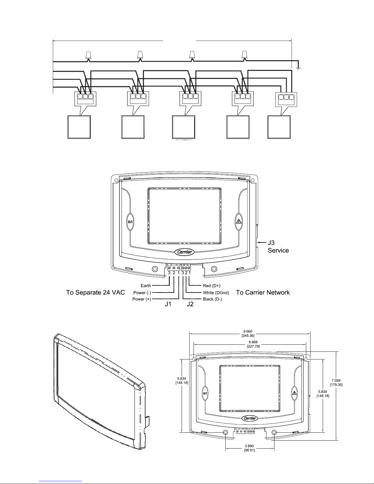
Wiring connections must be made in accordance with NEC
(National Electrical Code) and local codes. Ground one side
of the transformer secondary at the transformer location.
Connect the system ground of the transformer to the Dis-
play terminal J1-3 (EARTH). Connect the 24 Vac– side of
the transformer to the Display terminal J1-2 (24 Vac–). Con-
nect the 24 Vac+ live side of the transformer to the Display
terminal J1-1 (24 Vac+). See Figure 2 on page 3. The power
supply is 24 Vac at 60 Hz ± 15%, 10 VA minimum.
NOTE: Do not run sensor or communication wiring in the
same conduit with line-voltage wiring. Do not run 24 Vac
wiring in the same multi-conductor cable used for sensors
or communications.
Perform the following steps to connect the power trans-
former:
1. Install the field-supplied transformer in an electrical en-
closure that conforms to NEC and local codes.
2. Connect 24 Vac from the transformer as shown in the
wiring diagram (Figure 2). Be sure to observe polarity
when connecting the transformer power. The grounded
terminal must be connected to the transformer ground
terminal as described previously under Power Transformer
Wiring.
If the Display is powered with the same transformer as
the other devices, be sure that polarity is maintained and
that adequate power is available for all devices. Never
power half-wave and full-wave devices on the same trans-
former or damage may occur to one or both devices.
Carrier Network Communication Bus Wiring —
The Touch Pilot connects to the bus in a daisy chain ar-
rangement. See Figure 1 on page 3. It may be installed on a
primary Carrier communication bus or on a local bus wired
to an equipment controller’s LEN (Local Equipment Net-
work) port.
At any baud (9600, 19200, 38400 baud), the number of
controllers is limited to the application requirements. Bus
length may not exceed 4000 ft, with no more than 60 total
devices on any 1000-ft section. Optically isolated RS-485
repeaters are required every 1000 ft.
COMMUNICATION BUS WIRE SPECIFICATIONS —
The communication bus wiring is field-supplied and field
installed. It consists of shielded three-conductor cable with
drain (ground) wire. The cable selected must be identical to
the communication bus wire used for the entire network.
See Table 1 for recommended cable.
Table 1 — Recommended Cables
MANUFACTURER CABLEPARTNO.
Alpha 2413 or 5463
American A22503
Belden 8772
Columbia 02525
NOTE: Conductors and drain wire must be at least 20 AWG (American Wire Gage), stranded,
and tinned copper. Individual conductors must be insulated with PVC, PVC/nylon, vinyl, Teflon,
or polyethylene. An aluminum/polyester 100% foil shield and an outer jacket of PVC, PVC/
nylon, chrome vinyl, or Teflon with a minimum operating temperature range of –20 C to 60 C
is required.
CONNECTION TO THE COMMUNICATION BUS
1. Strip the ends of the red, white, and black conductors of
the communication bus cable.
2. Connect one end of the communication bus cable to the
communication port labeled CCN or COMM1 of the other
devices on the communication bus. See Figure 1. For net-
work applications, the CCN or COMM1 connector is typi-
cally the network bus connector.

2
When connecting the communication bus cable, a color
code system for the entire network is recommended to
simplify installation and checkout. See Table 2 for the
recommended color code.
Table 2 — Color Code Recommendations
SIGNALTYPE CCNBUSWIRECOLOR PLUGPINNO.
+ Red 1
Ground White 2
- Black 3
3. Connect the other end of the communication bus cable to
J2 on the Touch Pilot. See Figure 2. Following the color
code in Table 2, connect the Red (+) wire to Terminal J2-1
(D+). Connect the White (ground) wire to Terminal J2-2
(DGnd). Connect the Black (–) wire to Terminal J2-3 (D-).
4. If connecting to a Carrier communicating network bus,
connect additional devices in a daisy chain fashion, fol-
lowing the color coded wiring scheme in Table 2. See
Figure 1 on page 3.
NOTE: The communication bus drain wires (shield) must
be tied together at each device. If the communication bus is
entirely within one building, the resulting continuous shield
must be connected to ground at only one single point. If
the communication bus cable exits from one building and
enters another building, connect the shields to ground at a
lightning suppressor in each building where the cable en-
ters or exits (one point only).
Mounting —
SURFACE MOUNT — This provides surface mounting
configuration, which allows use of a small hole in the wall.
(See Figure 4 on page 3.) The assembly will mount directly
to the wall, requiring only a small hole in the wall allowing
the wiring connection to pass through. Use four #8 x 1.5 in.
Phillips panhead screws and four wall anchors to fasten the
Display to the wall.
DECORATIVE BEZEL— A decorative bezel is supplied. Af-
ter mounting and wiring the Display snap the decorative
bezel on the Display to cover the mounting holes and screws
and hide the wire connectors. See Figure 3.
DISPLAY MOUNTING — Perform the steps below to mount
the Touch Pilot.
1. Before installing the Display, turn off all power to equip-
ment. There may be more than one power source to dis-
connect.
2. Route wires through large hole in wall if applicable. Level
rear Display against wall and mark wall through four
mounting holes.
3. Drill four 3/16-in. mounting holes in wall where marked in
Step 2.
4. Secure the Display to wall using four screws and anchors
(field-provided).
5. Adjust length and routing of each wire to reach the termi-
nal on the connector at the bottom of the Display. Strip
1/4-in. of insulation from each wire.
6. Match and connect wires to proper terminals on the Dis-
play backplate. See wiring diagram Figure 2.
The connector may be removed from the Display to make
terminal connection easier.
NOTE: Existing wiring must meet wiring specifications
defined in this manual.
7. Push any excess wire into the wall. Seal hole in wall to
prevent any air leaks. Leaks can affect operation.
8. Attach bezel.
9. Turn on power to equipment.

3
Figure 1 — Carrier Communicating Network (CCN) Bus Wiring
Figure 2 — Touch Pilot Wiring
123654123
COMM
GN
D
1000 FT MAXIMUM
DRAIN WIRE (TYP)
BLK (TYP)
WHT (TYP)
RED (TYP)
BYPASS
CONTROLLER ZONE
CONTROLLER SYSTEM
PILOT ZONE
CONTROLLER BRIDGE
(RECOMMENDED)
123123
CCNCCNCCN CCN
CHILLER
DISPLAY
Figure 3 — Touch Pilot Bezel Figure 4 — Touch Pilot Surface Mounting

4
OPERATION
Power-Up Display – When the Touch Pilot is powered-
up it displays an Initialization progress bar and attaches
(initiates communication) to a controller that has been des-
ignated as the Default device. The Touch Pilot then dis-
plays that controller's default Group Display (Figure 5), or if
the controller does not have Group Displays, displays that
controller's generic Controller Default Screen table. If a De-
fault device has not been specified, or if the Display cannot
communicate with it, the the Main Menu (Figure 6) will be
displayed on power-up.
NOTE: Touching the screen anywhere for 5 seconds while
powering-up will promt you to restore contrast and calibra-
tion settings to factory defaults.
DEFAULT DEVICE DESIGNATION –The Default device is
the first entry in the Attach (Network Device) List. This list
is accessed using the Main Menu's Attach option. For ad-
ditional information, refer to Attach, which appears in the
Main Menu section of this manual.
DEFAULT GROUP DESIGNATION – The default group is
one of the attached controller's up to 8 group displays.
Group point complements default to factory-assigned
configurations in the specific CCN device, but are user-
modifiable from the Touch Pilot. Refer to Group Display,
which appears later in this manual. Currently, only the
30XA AQUAFORCETM chiller contains all 8 group displays.
Going forward, more Carrier equipment will support this
group functionality.
Following installation and initial power-up, the installer
should Login and then select the Setup option from the
Main Menu to access the display's various setup and con-
figuration functions. Refer to Login and Setup, which ap-
pear in the Main Menu section of this manual.
Figure 5 - Example of a Group Display Screen
Figure 6 - Main Menu
Figure 7 - Example of a Generic Controller
Default Screen
Group Display Screen – The Touch Pilot supports up
to eight Group Display screens. A Group Display screen
shows status information and nine buttons that display the
first nine point names and values read from the attached
device. Each button displays the point name and the value.
If a point has an alarm, alert, or sensor failure, the point
button will be in inverse video. If there is a communication
failure with the attached device, all point buttons will be in
inverse video and the message Communication failure will
be displayed in the top left line of the screen. The bottom
line contains navigation buttons that allow you to move
between the Group Display screens. Refer to the Naviga-
tion and Operation Pushbuttons section of this manual for
additional information.
Pressing a point button will show the point's Point Data
dialog box (Figure 8 and 9). This box contains buttons that
allow you to remove the point from the group display, and
to apply or remove a force (point override).

5
TO REMOVE A POINT FROM A GROUP DISPLAY – From
the Point Data Dialog box, press the REMOVE button
and follow the prompts. The display will return to
the Group Display screen from which the point was re-
moved, and the button corresponding to the deleted point
will be blank and disabled.
TO ADD A POINT TO A GROUP DISPLAY – From the
Main Menu, press the one of the table type buttons (Sta-
tus, Setpnt, Service, Maint, or Config) and press the but-
ton corresponding to the table that contains the point you
wish to add to the group (the source point). Press the point
button to show the source point's Point Data dialog box
(Figure 8 and 9). From the Point Data Dialog box, press the
ADD button . The Display will show the last Group
Display accessed. Use the and navigation but-
tons to access the destination Group Display. Press an ex-
isting point button or a blank button to update the high-
lighted button with the source point's name. Press
to add the highlighted point to the group and return to the
table display.
Figure 8 - Point Data Dialog Box - Dynamic Point
Figure 9 - Point Data Dialog Box - Static Point
Navigation and Operation Pushbuttons – The Touch
Pilot contains the following pushbuttons to allow you to
operate the display and to navigate within and between
screens.
BACK – Returns to the next higher screen in the
hierarchy.
HOME – Displays the Default screen (Default Group
Display if one is available, the generic Controller Default
Screen (Figure 7) if the attached device has no Group dis-
plays, or the Main Menu if the display is not attached to a
device).
MAIN MENU – Displays the Main Menu screen. A
description of all Main Menu options can be found in the
Main Menu section of this manual.
PREVIOUS – In a group of sequential screens of the
same type, moves to the next earlier screen in the group.
NEXT– In a group of sequential screens of the same
type, advances to the next screen in the group.
OK – Agrees with, or says “yes” to a prompt and
performs the appropriate processing.
NO – Rejects, or says “no” to a prompt and per-
forms the appropriate processing.
CANCEL – Terminates an ongoing action and re-
turns to the current screen without any other processing.
CLEAR DATA – Blanks the data value in a data
entry dialog box.
RESET DATA – Zeros the data value in a data entry
dialog box.
ADD – Adds a point to a Group Display screen.
REMOVE – Deletes a point from a Group Display
screen.
INC, DEC – Modify the value of a field within
its defined limits.
SCROLL UP, DOWN – Shifts the data on the
screen up or down by one item.
PAGE UP, DOWN – If the current table or list
has more data than will fit on the screen, replace the items
currently on the screen with the previous or next group of
items.
FORCE – Begins the process of forcing or overriding
the value of a point.
AUTO – Begins the process of removing a force
from a point.
MODIFY – Begins the process of modifying a con-
figuration value.
ALARM INDICATOR LIGHT – The Touch Pilot fea-
tures an LED alarm indicator light that is activated when a
new alarm condition has occurred on the Carrier communi-
cating network. The alarm indicator light, located on the
right side of the Display, remains activated until it is manu-
ally reset using the Main Menu's Reset button. When the
Display is in Network mode, the alarm indicator light does
not indicate communication failure with the attached de-
vice.

6
NOTE: In order for the Display to receive alarms from a
CCN device, the CCN user interface bit in the device's Alarm
Routing decision must be set to 1.
START/STOP BUTTON – The Touch Pilot includes an
equipment Start/Stop Button that enables you to start or
stop the Chiller.
NOTE: This button is not functional when the Display is in
Network mode.
Main Menu – Press the button to display the Main
Menu as shown in Figure 10 below. An explanation of each
Main Menu option follows.
Figure 10 - Main Menu
LOGIN – Pressing the button displays the Login
dialog box. Press the numbers to enter your four-digit pass-
word and press the OK button. Once you are logged in, the
LOGIN button will changed to LOGOUT, and the Display
will permit or restrict options corresponding to your access
level. Note that when you are logged out, you will have
read-only access. The Login dialog box will, however, be
displayed any time you are logged out and select an op-
tion/feature that requires Limited or Full Access levels. For
additional information on access levels, refer to SETUP in
the Main Menu section of this manual.
LOGOUT– Pressing the Main Menu's button dis-
plays a confirmation message asking you to confirm the
request to logout. Note that whenever you are logged out,
read-only access is still permitted.
Inactivity Timeout Feature - If there is no contact with the
touch screen panel or the Equipment Start/Stop hardware
button for a 15 minute period, the Display will automati-
cally logout and return to the Default display without sav-
ing any changes. While the Display is performing an At-
tach process, however, the inactivity timeout feature will be
disabled.
SETUP – Pressing the Main Menu's button
displays the Setup screen as shown in Figure 11, which is
displayed following this Main Menu section.
ATTACH – Pressing the Main Menu's button
will allow you to display the Attach list where you can
select an existing device or add a new device, and then
establish communication with the selected device. The At-
tach list consists of device name, bus and element num-
bers. The first entry in the Attach list (surrounded by two
**) is referred to as the Default device. It will be the device
to which the Display will automatically attach on power up.
The currently-attached device will be enclosed in angle
brackets (ex.: <<19XLCHR>>).
To Add a device to the Attach list: Add a new device to
the Attach list by pressing any Bus or Element button and
when prompted, entering the device's bus or element num-
ber.
To Attach to a device in the Attach list: Press the Name
button corresponding to the device to which you wish to
attach. You will then be presented with an Attach to this
device? confirmation message.
During the Attach process, the Display will upload all tables,
including any group displays, from the specified device.
On completion of a successful Attach, the Default display
will be shown. Note that the Inactivity Timeout feature will
be disabled while the Display is in the Attach process.
To Remove (reinitialize) an existing device from the At-
tach list: Modify the device's Bus and Element numbers to
zero and then touch the device's Name button.
To Clear (reinitialize) the entire Attach list: Press the
Clear the Controller List button, which is located immedi-
ately past the last device in the Attach list.
TIME – Pressing the Main Menu's button while
in Network mode will allow you to change the attached
device’s time and date and holiday status. If the Display is
unattached, it will display its own time and date (if the time
has been set). If the Broadcast check box on the Time/Date
screen is selected, you will be prompted to broadcast time,
date, and holiday status to all CCN devices on the network
upon exiting the Time/Date screen.

7
ALARMS – Pressing the Main Menu's button
will allow you to display device alarms from a selected Alarm
History table in the attached device or network alarms from
the CCN. To view device alarms, use the Alarm Table but-
tons (if the device has 2 or more alarm tables) or the
History button (if there is only 1 alarm table). To view
alarms from the CCN, use the Network button. Note that if
the Display is unattached or the attached device has no
Alarm History tables, the Table List screen will only con-
tain a Network button. Alarm History is a static screen. To
refresh the alarm list, you must exit and re-select the Alarms
option.
RESET – Pressing the Main Menu's button will
allow you to turn off the Display’s alarm indicator light.
The light will stay off until a new alarm condition is de-
tected.
SCHED – Pressing the Main Menu's button al-
lows you to display a CCN time schedule from the attached
device. If the attached device has just one time schedule,
the Display will bring up the Time Schedule screen. If the
device has multiple time schedules, the Display will show a
list of schedules from which you can select the one you
wish to access. The Time Schedule screen consists of eight
buttons, one for each occupancy period. Press a period
button to show the Period Edit dialog box for that period.
You will be prompted to save changes upon exiting the
Time Schedule screen.
STATUS, SETPNT, SERVICE, MAINT OR CONFIG – Press-
ing the
buttons allows you to display a status display,
setpoint, service configuration, maintenance, or configura-
tion table from the attached device. If there is just one
table of that type the Display will bring up the Table screen.
If the device has multiple tables of that type, the Display
will show a list of tables from which you can select the one
you wish to access.
As you make changes to values in these tables, the new
values will be displayed. On pressing a Navigation
pushbutton to exit the current screen, a confirmation mes-
sage will be displayed. Pressing will save and down-
load the new values to the attached device. Pressing
will exit the screen without saving or downloading the modi-
fied values. Pressing will cancel the changes and re-
turn you to the screen for further changes.
Setup Menu Screen – This screen (shown in Figure 11)
is accessed by pressing the Main Menu's Setup button.
Figure 11 - Setup Menu
The Setup Menu provides access to setup and configura-
tion functions for the Display itself. Table 3 summarizes
Setup Menu functions.
Table 3 - Setup Menu
Pressing Allows you to...
REGIONAL specify the time and date format and units
base.
LANGUAGE select the Display's active language and
font.
CONTRAST adjust the LCD contrast. Press and hold
the button to increase/darken or the
button to decrease/lighten the cur-
rent contrast. If when adjusting contrast
the screen becomes unreadable, follow the
instructions under Calibrate below to re-
turn the screen to the factory default.
BACKLIGHT specify whether backlighting should be
kept on at all times or turned off during
inactive periods.
CALIBRATE adjust the LCD touch screen calibration.
Using a fine point device, touch the
screen in the center of the circular targets
located first in the upper left and then in
the lower right corner of the screen. If,
during the calibration procedure, a mis-
take is made the screen may be reset to
factory defaults by simultaneously touch-
ing the screen and performing a power
cycle. When prompted, touch the screen
anywhere.
(Table 3 - continued on the next page)

8
Table 3 - Setup Menu (continued)
Pressing Allows you to...
PASSWORDS configure limited and full logged-in access
system passwords. Note that you must
be logged in with full access to view and
change the passwords. All passwords
must consist of 4-digits, which you can
enter using the numeric keypad.
Access levels and associated privileges
are as follows:
Limited Logged-in Access - provides you
with read/write access to all available
tables (except service configuration tables,
where you will not be permitted to modify
point data, and Group Display tables,
where you will not be permitted to add
points.) This access level also provides
read/write access to all Display Setup prop-
erties except Display, CCN, and Password.
Full Logged-in Access - provides you
with read/write access to all available
tables for the attached device and all Dis-
play properties.
Note that if you do not log in, you will
have read-only access to all tables in the
attached device. You will be prompted to
log in when attempting to access pass-
word-required functions.
DISPLAY view data from the Display's Ctlr-ID Table
and specify the Display's Operating
Mode. Equipment mode provides access
only to the Default device or to the de-
vice currently connected to the Display's
RS-485 connector (via the Local Equip-
ment Network (LEN) Bus). Network mode
provides access to all devices on the CCN
Bus connected to the Display's RS-485
connector.
NOTE: When changing the operating
mode, a power cycle is required in order
for the new operating mode to take effect.
CCN view and modify the following CCN data:
address and baud rate, alarm
acknowledger and broadcast
acknowledger designation.
CONFIGURATION TABLES
Display operation is controlled by decisions entered in the
the following configuration tables, which are accessible from
a Carrier front end such as the Network Service Tool or
ComfortVIEW:
• CtlrID – Controller Identification Configuration Table
• USERCONF – User Configuration Table
NOTE: You should always perform an Upload to obtain the
latest configuration before making configuration table
changes.
User Configuration (USERCONF) Table – The User
Configuration table is shown in Figure 12. Each decision is
explained below.
Backlight Always On? – Use this decision to indicate
whether to keep the backlight on continuously, or whether
to turn it off after 60 seconds with no activity.
Allowable Entries: No/Yes (No=0 or Yes=1)
Default Value: No
Full Access Password – Use this decision to specify the
full access password. Refer to Table 1 - Setup Menu for
additional information on passwords.
Allowable Entries: 0 through 9999
Default Value: 3333
Limited Access Password – Use this decision to specify
the limited access password.
Allowable Entries: 0 through 9999
Default Value: 2222
Active Language – Use this decision to specify the Display's
active language. All translatable text will be displayed in
this language.
Allowable Entries: 0 through 1
Default Value: 0
Time Format – Use this decision to specify the format for
display of time.
Allowable Entries: 0 = H:MM AM/PM without leading
zero
1 = HH:MM with leading zero when
necessary
Default Value: 0
Date Format – Use this decision to specify the format for
display of date.
Allowable Entries: 0 = MM-DD-YYYY with leading zero
when necessary
1 = DD-MM-YYYY with leading zero
when necessary
2 = YYYY-MM-DD
Default Value: 0
Units Base – Use this decision to specify engineering
units.
Allowable Entries: 0 = U.S.
1 = Metric
Default Value: 0
Contrast Control – Use this decision to enable or disable

9
the Display's auto contrast adjustment feature. When en-
abled, the Display's contrast will be automatically adjusted
as required, based on temperature.
Allowable Entries: 0 = Manual
(Auto Contrast Adjustment Disabled)
1 = Auto
(Auto Contrast Adjustment Enabled)
Default Value: 1
Network Mode – Use this decision to set the Display's
operating mode. For additional information on operating
mode, refer to Display in Table 1 - Setup Menu. This deci-
sion will be ignored and the mode will default to Equipment
when the Display is connected to a device (the LEN Bus).
NOTE: A power cycle is required for this decision to take
effect.
Allowable Entries: 0 = Equipment Mode
1 = Network Mode
Default Value: 0
Network Settings
Alarm Acknowledger – Use this decision to specify
whether the Touch Pilot will act as the alarm acknowledger
for its CCN. There must be only one alarm acknowledger
per CCN. Therefore, if another CCN device such as
ComfortVIEW, the Autodial Gateway or TeLINK is already
set as the Alarm Acknowledger for the CCN then this deci-
sion should be set to No.
NOTE: The Display must be in Network mode and con-
nected to the primary CCN Bus and this decision set to Yes
for alarm acknowledgement to be enabled.
Allowable Entries: 0 = No
1 = Yes
Default Value: 0
Broadcast Acknowledger – Use this decision to indicate
whether the Touch Pilot will act as the broadcast
acknowledger for its CCN Bus. There must be 1 (and only
1) broadcast acknowledger per CCN Bus.
NOTE: The Display must be in Network mode and this
Figure 12 - User (USERCONF) Configuration
Table

10
decision set to Yes for broadcast acknowledgement to be
enabled.
Allowable Entries: 0 = No
1 = Yes
Default Value: 0
Equipment CCN Address –
When in equipment mode (USERCONF Table's Network
Mode decision is set to Disable), the Bus Number and
Element Number decisions are used to specify the CCN ad-
dress of the piece of equipment to which you wish to com-
municate. You must perform an Attach or cycle power for
changes to these decisions to take effect. These decisions
will be ignored when the Display is connected to the LEN
bus or in Network mode. In network mode, you specify the
bus and element number of the equipment to which you
wish to communicate using the Display's Attach function.
For additional information, see Attach in the Main Menu
section of this manual.
NOTE: In Network mode, these decisions will be overwrit-
ten with the Default device address if it is changed through
the Attach process.
Bus Number – Use this decision to specify the Equipment
Controller bus number .
Allowable Entries: 0 through 239
Default Value: 0
Element Number – Use this decision to specify the Equip-
ment Controller element number .
Allowable Entries: 1 through 239
Default Value: 1
Control Variables
Use the next 4 decisions to specify the names of the CCN
equipment variables that will be used to implement the Start/
Stop Control and Alarm Indication functionality.
Equipment Status – This decision is used in conjunction
with the Display's Start/Stop button. Enter the CCN variable
name of the equipment input point to which the on/off sta-
tus indicator is connected. This name can be obtained from
the CCN equipment's status display table. This decision will
be ignored when the Display is in network mode.
Allowable Entries: Up to 8 character CCN variable name
Valid characters include A to Z,
0 to 9, dash and underscore
Default Value: blank = Disable START/STOP control
Equipment Start/Stop – This decision is used in conjunc-
tion with the Display's Start/Stop button. Enter the CCN
variable name of the equipment point to which the Start/
Stop output point is connected. If you press the button
while in equipment mode, the Display will first look at the
equipment point's status (in accordance with the variable
name you entered in the Equipment Status decision above)
and then start or stop the equipment point that you specify
in this decision. This name can be obtained from the CCN
equipment's status display table. This decision will be ig-
nored when the Display is in network mode.
Allowable Entries: Up to 8 character CCN variable name
Valid characters include A to Z,
0 to 9, dash and underscore
Default Value: blank = Disable START/STOP control
Alarm Status – This decision is used in conjunction with
the Display's Alarm Indicator light. When in equipment
mode, the Display will read the value of the input point that
you specify in this decision and will turn the indicator light
on or off accordingly. Enter the CCN variable name of the
equipment input point to which the alarm status indicator is
connected. This name can be obtained from the attached
device's status display table. This decision will be ignored
when the Display is in network mode or attached to a
AquaForce™chiller.
Allowable Entries: Up to 8 character CCN variable name
Valid characters include A to Z,
0 to 9, dash and underscore
Default Value: blank
Alarm Reset – This decision is used in conjunction with
the Reset button on the Main Menu. When in equipment
mode, the Display will reset the alarm status equipment point
that you specify in this decision and will turn off the Alarm
Indicator light when the Reset button is pressed. This deci-
sion will be ignored when the Display is in network mode or
attached to an AquaForce chiller.
Allowable Entries: Up to 8 character CCN variable name
Valid characters include A to Z,
0 to 9, dash and underscore
Default Value: blank
Table of contents
Other Carrier Touch Panel manuals