Copyright © 2023 by Cartell
CONTACT INFORMATION
TECH SUPPORT/RMAs 717-532-0033, opon 1
SHIPPING 717-532-0033, opon 2
ACCOUNTING 717-532-0033, opon 3
INSIDE SALES 717-532-0033, opon 4
ORDERING
ADDRESS 510 West King Street
Shippensburg, PA 17257
WEBSITE www.cartell.com
CONSUMER: Contact your installer.
INSTALLER: CALL BEFORE DIGGING UP OR UNINSTALLING
Call (717) 532-0033, opon 1 to troubleshoot and receive a Return
Merchandise Authorizaon (R.M.A.) number. Write R.M.A. number on shipping
box and any correspondence included with defecve product.
DISTRIBUTOR: Send installers directly to Cartell, cing 717-532-0033 (opon
1) as phone number.
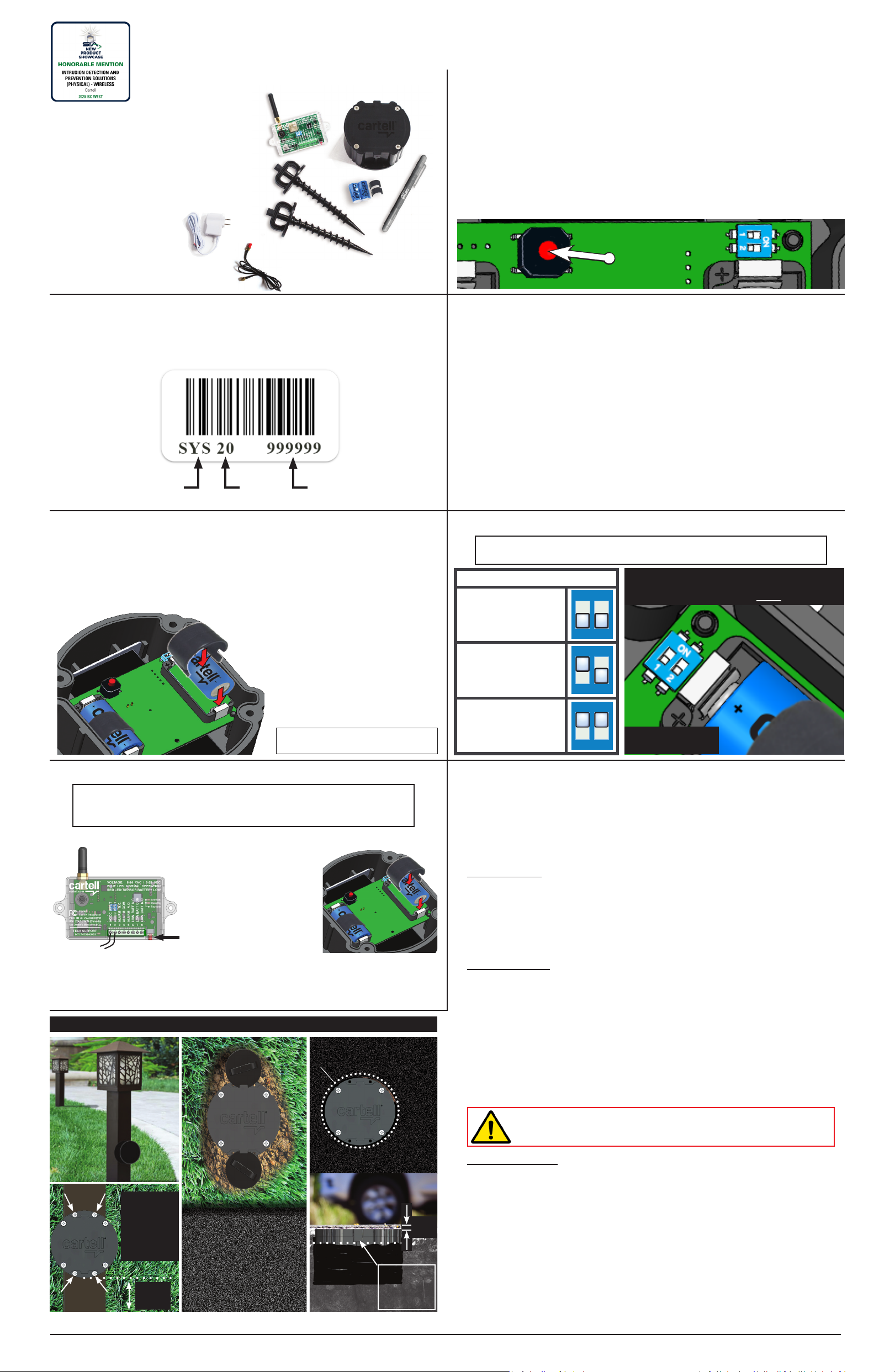
9. INTEGRATOR DIP SWITCHES
Dip switches control sounder and repeater mode on Integrator.
SOUNDER
Turn dip switch 1 ON to turn sounder on.
Sounder will beep 3 mes when vehicle is detected. It will also “chirp” when
sensor puck baeries are low and need replacing.
REPEATER MODE
Turn dip switch 2 ON to turn Integrator into a repeater. In repeater mode,
the unit will connually receive and repeat any signal from the sensor to
the Integrator installed in the home (see #11 below). Red and blue LED will
alternately and connuously blink in repeater mode.
10. INSTALLING INTEGRATOR
11. REPEATER MODE
To increase radio range, it may be necessary to make the Integrator a repeater.
If the signal from sensor puck is not reaching the Integrator:
1. Move the sensor closer to the Integrator, and/or
2. Install a repeater in the home between the sensor puck and Integrator
connected to the security/home automaon system. Do the following:
1. Purchase an oponal Integrator and power supply (Product CW-REP).
2. Remove enclosure cover by carefully pushing side tabs in.
3. Connect power supply to terminals 1 & 2 (no polarity).
4. Turn dip switch 2 ON (see #9 above). This puts the unit in repeater
mode. The red and blue LEDs will alternately blink to indicate repeater mode. It
will connually receive every signal from the sensor and transmit (repeat) it to
the Integrator installed beside the main system.
5. Install repeater in a window closest to the sensor puck.
6. Turn dip switch 1 OFF to turn sounder o.
NOTE: To order repeater kit, use product code CW-REP.
This device complies with part 15 of the FCC Rules. Operaon is subject to the following two
condions: (1) this device may not cause harmful interference, and (2) this device must accept
any interference received, including interference that may cause undesired operaon. Any
changes or modicaons not expressly approved by the party responsible for compliance could
void the user’s authority to operate the equipment.
NOTE: This equipment has been tested and found to comply with the limits for a Class B digital
device, pursuant to Part 15 of the FCC Rules. These limits are designed to provide reasonable
protecon against harmful interference in a residenal installaon. This equipment generates,
uses and can radiate radio frequency energy and, if not installed and used in accordance with
the instrucons, may cause harmful interference to radio communicaons. However, there is no
guarantee that interference will not occur in a parcular installaon.
If this equipment does cause harmful interference to radio or television recepon, which can
be determined by turning the equipment o and on, the user is encouraged to try to correct the
interference by one or more of the following measures:
Reorient or relocate the receiving antenna.
Increase the separaon between the equipment and receiver.
Connect the equipment into an outlet on a circuit dierent from that of thr receiver.
Consult the dealer or an experienced radio/TV technician for help.
To maintain compliance with FCC’s RF Exposure guidelines, This equipment should be installed
and operated with minimum distance between 20cm the radiator your body: Use only the
supplied antenna.
IC Cauon (Canada): This device complies with Industry Canada licence-exempt RSS
standard(s). Operaon is subject to the following two condions: (1) this device may not cause
interference; (2) this device must accept any interference, including interference that may cause
undesired operaon of the device.
This Class [B] digital apparatus complies with Canadian ICE-003.
Le présent appareil est conforme aux CNR d’Industrie Canada applicables aux appareils radio
exempts de licence. L’exploitaon est autorisée aux deux condions suivantes: (1) l’appareil ne
doit pas produire de brouillage, et; (2) l’ulisateur de l’appareil doit accepter tout brouillage
radioélectrique subi, même si le brouillage est suscepble d’en compromere le fonconnement.
Cet appareil numérique de la classe [B] est conforme à la norme NMB-003 du Canada.
L’appareil a été évalué pour répondre aux exigences générales d’exposion RF. L’appareil peut
être ulisé dans des condions d’exposion xes / mobiles. La distance de séparaon minimale
est de 20 cm.
The device has been evaluated portable device RF exposure requirements. The device is kept
at least 5 mm away from the user’s body.
TO LOW
BATTERY
INPUTS
TO LOW
BATTERY
INPUTS
TO ZONE
INPUTS or
WIRELESS
SWITCH
IF N.O.
TO ZONE
INPUTS or
WIRELESS
SWITCH
IF N.C.
POWER +
POWER -
LOW BATTERY
N.C. N.O.COM
ALARM RELAY
N.O.COMN.C.
(No Polarity)
POWER
SECURITY/HOME AUTO SYSTEMS
DO NOT USE
TO EXIT
TERMINALS
TO EXIT
TEMINALS
POWER +
POWER -
N.C. N.O.COM
LOW BATTERY
N.O.COMN.C.
ALARM
(No Polarity)
POWER
Your system integrates seamlessly with any security/H.A. system or electric
gate operator. To integrate, use the following wiring schemacs as guides:
DO NOT USE
TO “EXIT”
or “OPEN”
TERMINAL
TO “GND”
or “COM”
(use one)
POWER +
N.C. N.O.COM
LOW BATTERY
N.O.COMN.C.
ALARM
(No Polarity)
POWER
Technical Specifications
Sensor “Puck” Integrator
Power Required 2 - CR123A batteries (6 V) 8-24VAC; 8-28VDC
Stand-By Current 22 Microamps (A) 25 Milliamps (mA)
Alarm Current 130 Milliamps (mA) 40-80 Milliamps (mA)
Relay Time ― 2 seconds
Relay Contacts ―SPDT, N.O. or N.C. (Form C)
Relay Contact
Rating ―2 amp/24 VDC (1 mA at
5 VDC min. load)
Radio Range
Tested above ground, no obstructions, up to 2,500 ft.*
Tested flush with ground, no obstructions, up to 1,000 ft.*
Use optional Repeater (CW-REP) to increase radio range
Battery Life 1-3 years*―
Enclosure Rating IP68 ―
Strength Rating 9.39 ton-force (8514 kgf) –
Temperature Range -25° F. +140° F.
(-32° C. 60° C.)
Dimensions 4.5"dia. x 2.5"H
(11.43 cm x 6.35 cm)
3.25"L x 2"H x .875" D
(8.25 cm x 5.08 cm x 2.22 cm)
Weight 2 lbs. (.90 kg) 1 lb. (.45 kg)
* Esmate only. Radio range & baery life depend on many variables. No guarantees.
Integrator uses 8-24 VAC or 8-30
VDC. Use security/H.A. system or
gate operator to power or use any
12VDC power supply. Cartell sells
oponal power supply (Part #CW-PS).
All Cartell products are warranted against defects in
material and workmanship for ve years. This warranty
does not cover defects caused by, but not limited to:
acts of God, improper installaon, abuse, re damage,
electrical surges, integrated system failures, improper
lid/gasket/baery installaon, overghtening screws, and
stripping screw holes.
W
A
R
R
A
N
T
Y
W
A
R
R
A
N
T
Y
W
A
R
R
A
N
T
Y
Y
E
A
R
14. FIVE YEAR WARRANTY
13. RETURNING MERCHANDISE
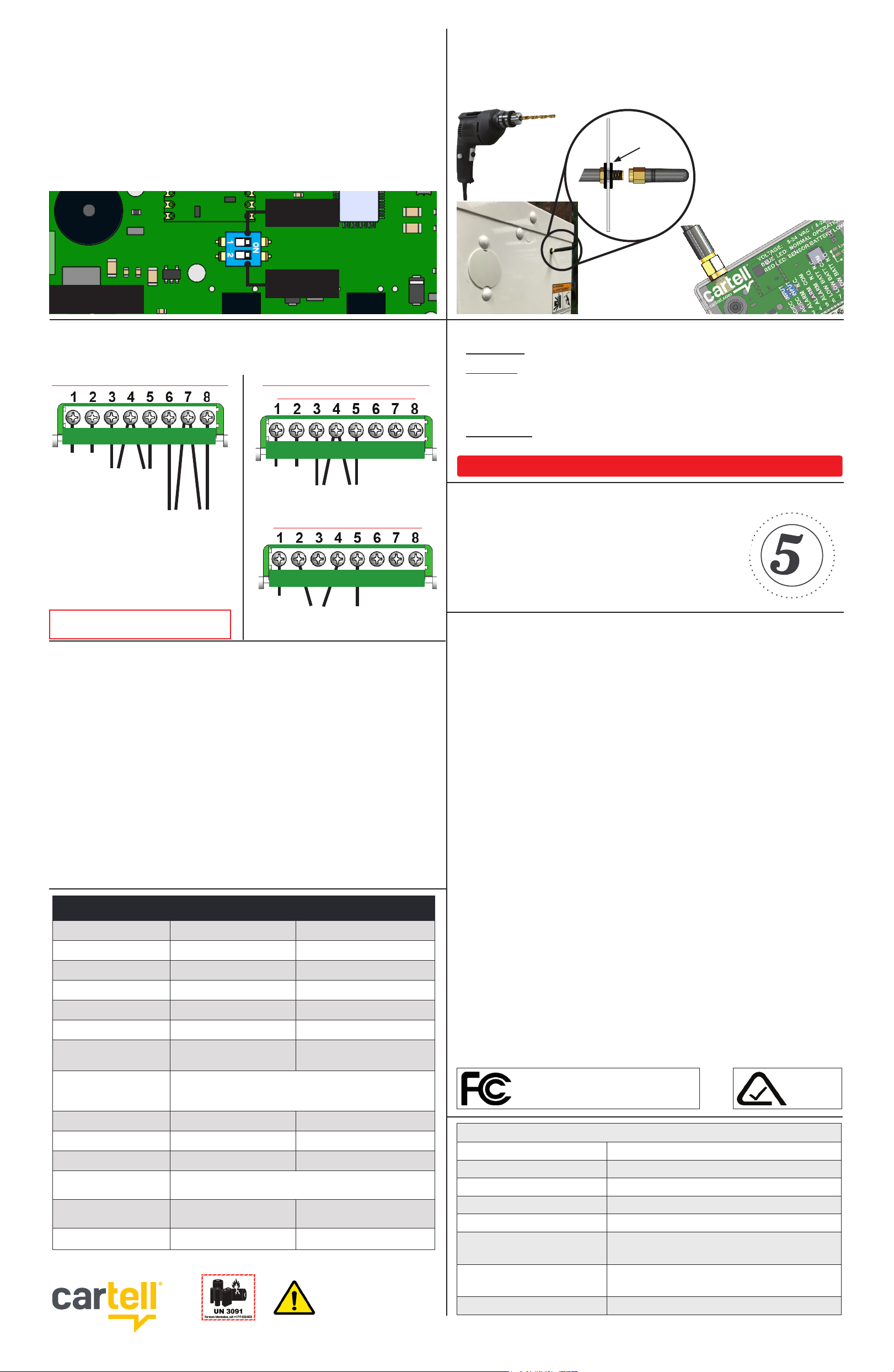
12. OPTIONAL EXTERNAL GATE ANTENNA
In gate operator installaons, antenna aached directly to Integrator will
work in most cases. The only me it may not work is in a sealed metal gate
operator that blocks the RF signal. If that is the case, use an oponal coaxial
cable and 3/8” grommet, and install antenna externally, per the following:
1. Drill 3/8”
hole in side
or boom
of operator.
2. Insert 3/8” grommet in drilled
hole.
4. Screw antenna on male
threads.
WARNING: DO NOT SHIP BATTERIES WHEN RETURNING PRODUCT TO CARTELL.
NOTE: DIP SWITCH
COLOR MAY VARY
#1 Sounder
mode ON
#2 Repeater
mode ON
5. Screw other end of cable to
Integrator antenna connector.
WARNING: This product can expose
you to chemicals including Acrylonitrile,
which is know to the State of California
to cause cancer. For more information,
go to www.P65Warnings.ca.gov.
AUTOMATIC GATE OPERATORS
15. FCC WARNING
SECURITY/HOME AUTO SYSTEMS
YOU MUST ADD A SAFETY TO GATE
WHEN USING CW-SYS FOR FREE EXIT.
E3957
AUSTRALIA
FCC ID #: 2AUXCCWIN & 2AUXCCWSN (U.S.)
IC#: 25651-CWIN & 25651-CWSN (Canada)
3. Push male threads of cable
through grommet.
GROMMET