CARVIN BX250 User manual

The BX250/MB Series MicroBass Amplifiers offer classic natural bass tone
with unprecedented tonal control and extended headroom. The BX250 Head
and Combo amps deliver 200w at 8 ohms and 250w at 4ohms.
Four discrete Class A input stages produce the harmonic basis for the preamp
right from the input jack. It begins with a boutique flat response, then we add
extensive tone control allowing you to carve out your signature sound. Harmonic
content increases as you turn up the DRIVE control producing rich harmonics
at maximum settings. The CLASS-D output and lightweight switch-mode power
supply use far less energy from the wall and produces less heat.
Light weight, solid design, bullet-proof construction and a list of indispensable
features make sure the BX/MB amps will be your choice for years to come.
•DiscreteCLASSAinputstages
•PreampDRIVEandMASTERvolumecontrols
•2midsweepsemi-parametricEQ,BASSandTREBLE
•CONTOURpre-shapecontrol
•SingleknobCOMPRESSOR
•DIRECTOUTbalancedXLRwithLEVEL,PRE/POSTandGROUND/LIFT
•MUTEswitchallowssilenttuningorheadphonepractice
•TUNER/PHONESoutputjackindependentofMUTEswitch
•TWEETERDIMswitchallowscontrolofspeakerbrightness(combo)
•CLASS-Damplifierrunscoolwhileconsuminglesspower
•Solidmetalshaftcontrolswithpanelmountedthreadedmetalbushings
•CircuitboardsareMILSPEC,doublesided,FR-4glassepoxy
•Energyefficientworldwidepowersupplyaccepts90-250VAC,50-60Hz
•Compactandlightweight.
GETTING STARTED
1.WithPOWERoff,connectaninstrumenttotheINPUTjack.Ifyouhavethe
BX250head,alsoconnectaspeakertoaspeakeroutjack.(4ohmsorhigher)
2.SettheDRIVEandMASTERvolumeto“0”andsettheACTIVEINPUTswitch
for your type of bass.
3.Setthefourtonecontrolstotheircenter“0”positionandtheCONTOURto
FLAT.Thisisthe“FLAT”settingfortheamp.
4.Now,turntheampON.Turnupthevolumeonyourbassguitar.Gradually
increasetheMASTERcontroltothedesiredlevel.Ifnosoundisheardturn
downtheMASTER,checktheMUTEswitch,speakerconnections,andthe
POWER(blue)/PROTECT(red)LED.
5. Increasing the DRIVE control will add harmonic richness to your sound.
TurninguptheDRIVEalsoincreasesvolume.Re-adjusttheMASTERvolume
after adjusting the DRIVE.
6.Adjustthetonecontrolstoyourliking.Keepinmindthatturningupatone
control isn’t always the answer. Sometimes turning down one of the MID
controls will get you the sound you want.
7.Needmorevolume?Thereisalimittotheamountofvolumeaspeakercan
produce and driving a speaker beyond it’s limit can damage it. Even though
these are powerful amplifiers, adding another speaker is the only way for
substantially more output. Doubling your speakers increases your acoustic
output by a factor of four.
Have fun exploring the features and sounds of your BX/MB amp. Take the
timewithyournewamptorealizeit’sfullpotential.
RECEIVING INSPECTION—read before getting started
INSPECTYOURUNITFORDAMAGEwhichmayhaveoccurredduringshipping.Ifdamage
isfound,pleasenotifytheshippingcompanyandCARVINimmediately.
SAVETHECARTON&ALLPACKINGMATERIALS.Intheeventyouhavetore-shipyour
unit, always use the original carton and packing material. This will provide the best possible
protectionduringshipment.CARVINandtheshippingcompanyarenotliableforanydamage
caused by improper packing.
SAVEYOURINVOICE.Itwillberequiredforwarrantyserviceifneededinthefuture.
SHIPMENTSHORTAGE.Ifyoufinditemsmissing,theymayhavebeenshippedseparately.
Pleaseallowseveraldaysfortherestofyourordertoarrivebeforeinquiring.
RECORDTHESERIALNUMBERontheenclosedwarrantycardforyourrecords.Keepyour
portion of the card and return the portion with your name and comments to us.
USAcustomersregisteronlineat:www.carvinaudio.com/pages/registration
SPECIFICATIONS:
OUTPUT POWER (all models)
8ohms, THD <1.0% 200w
4ohms, THD <1.0% 250w
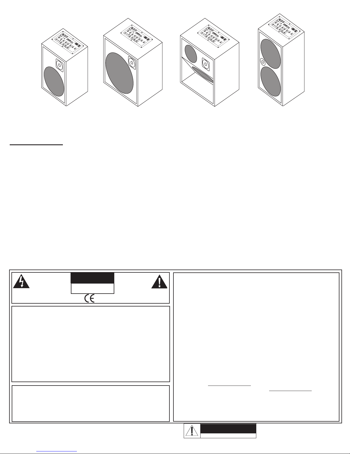
Combo Speaker Configuration: MB10: 2-way; 10” LF / 1” NEO HF
(all models 8 ohms) MB15: 2-way; 15” LF / 1” NEO HF
MB12: 3-way; 12” LF / 6.5” NEO MID / 1” NEO HF
MB210: 2-way; 2x10” LF / 1” NEO HF
Input Impedance: >200K
Drive Control: Variesinputgainandharmoniccontent
Tone Controls: CONTOUR pre-shape
BASS 50Hz
2 semi-parametric MIDs: 50Hz-500Hz / 200Hz-2kHz
TREBLE 10kHz
AC Requirements: 90to250VAC50/60Hz
Power Requirements: 200VA
Dimensions
BX250 (HEAD):
3.7”Hx10”Wx7.25”D(93x254x184mm)
MB10:
18.5”Hx12.75”Wx11.5”D(470x324x280mm)
MB12:
18.5”Hx17”Wx12”D(470x432x305mm)
MB15:
18.5”Hx17”Wx12”D(470x432x305mm)
MB210:
24.5”Hx12.75”Wx11.5”D(622x324x292mm)
Weight : BX250 (HEAD):3.2lbs.(1.5kgs)
MB10:26.1lbs.(11.85kgs)
MB12:30.5lbs.(13.85kgs)
MB15:32.6lbs.(14.8kgs)
MB210:36lbs.(16.33kgs)
Warranty: Oneyearpartsandlabor
Optional Accessories: Extensionspeakercabs:115MBE1x15”,210MBE 2x10”
Vinylcovers:CVMB10, CVMB12, CVMB15, CVMB210
MB15
MB10 MB12
BX250 HEAD
MB210
16262 WEST BERNARDO DR. SAN DIEGO, CA 92127
800-854-2235 CARVINAUDIO.COM
USER MANUAL
BX250 and MB series MicroBass Amplifiers
optional color shown

BX250/MB COMBO CONTROLS
1. INPUT JACK
The1/4”phonejackisahighimpedanceinstrumentinputdesignedto
handle both active and passive basses in connection with the ACTIVE
switch.
2. JEWEL LIGHT
BLUE = POWER ON/SYSTEM NORMAL
RED = STARTUP/MUTE/COMP/PROTECT
ThePOWERswitchturnsontheamplifier,andwhenthejewellightturns
BLUEtheampisreadyforuse.
The jewel light turns RED under different conditions. RED first appears at
POWERONforafewsecondswhiletheampstartsupandischeckedby
protectioncircuits.AsolidREDwillindicatetheMUTEswitchisengaged.
RED will FLASH as the COMPRESSOR is working. A solid RED (not
MUTEswitched)canalsoindicateaPROTECTmode,mostlikelyifthe
SPEAKEROUTPUTisshortedorifitisloadedbelowit’sminimumrating.
IfthepowerindicatorturnsOFF,orsolidRED(notmuted)whileplaying,
resettheampbyturningthePOWERswitchOFFforabout10seconds.
Checkanyexternalspeakerconnections.TurnthePOWERswitchbackON.
3. MUTE SWITCH
TheMUTEswitchturnsoffthesignaltotheamplifierandtheDIRECT
OUT.TheJEWELLIGHTchangestoREDtoindicatetheMUTEswitchis
on.TheMUTEswitchisidealforchangingbasses,silenttuningon-stage,
orheadphone-onlypractice.TheTUNER/PHONESoutputisnevermuted.
(BX250head:MUTE=in)
4. ACTIVE SWITCH
FliptheACTIVEswitchtotheDOWNpositionforstandardbasspickups.
If your bass uses a battery with an onboard active preamp, put the switch
intheUPposition.(BX250head:ACTIVE=in)
5. DI LEVEL (DIRECT OUT, PHONES)
TheDILEVELcontrolstheoutputleveloftheXLRDIRECTOUTandthe
1/4”PHONES/TUNERjack.TheDIlevelisnotaffectedbytheMASTER
level.UsePRE/POSTswitchtoselectiftheDRIVE,COMPRESSORand
TONEcontrolsaffectthissignal.
6. DRIVE CONTROL
The DRIVE control adjusts the input level to the CLASS A preamps. The
DRIVE control serves two purposes. The DRIVE can be used to adjust the
input sensitivity for the differences in bass pickups. The DRIVE will also
change the harmonic content of your sound. Turning the knob closer to
10 will create a more overdriven tone. The DRIVE will also change the
volumeoftheamplifier,useitincombinationwiththeMASTERcontrol
to achieve the desired volume.
7. CONTOUR CONTROL
TheCONTOURcontrolprovidesavariablemid-rangescoop.Whenthis
controlissetto“FLAT”thereisnochangetothemid-rangefrequencies.
As you turn the contour control clockwise, the mid range is scooped at
thecenterfrequency at 350Hz.Whenthe CONTOUR controlisset to
maximumthemid-rangeiscutby-15dBat500Hz.
8. BASS AND TREBLE TONE CONTROLS
TheBASSandTREBLE
controls are custom shaped tone controls designed to deliver punchy lows
andcrisphighsforavarietyofbasssounds.Whenacontrolisturnedto
the right it boosts the signal and when turned to the left cuts the signal.
TheaffectedfrequenciesfortheBASSstartat80Hzandcandeliveragreat
dealofvolume.Becarefulnottodistorttheoutputoroverpoweryour
speakers.TheaffectedfrequencyfortheTREBLEcontrolbeginsat5kHz
2
13
13 6 4 5 7 8 10 9 8 11
12 14 15 17 16 19 18

9. SEMI-PARAMETRIC MIS SWEEP TONE CONTROLS
(LO MID, HI MID & FREQ)
StartwiththeLOMIDsweep.TheFREQcontroldoesnotfunctionifthe
GAINcontrolissetinthecenter“0”position.Todemonstrate,turnthe
GAINtotherightforfullboost.NowplayyourbassandturntheFREQ
control from left to right and notice the how the added mids change
frequency.NowturntheGAINtothefullleftandturntheFREQcontrol
again and notice the mids disappear at different frequencies. Try this with
theHIMIDalso.Themidsweepsystemcontrolscanbeveryeffectiveto
fine tune your overall sound.
10. COMPRESSOR
The compressor reduces the volume of the incoming signal as it
reachesapresetmaximumlevel.AstheCOMPRESSORknobisturned
up (clockwise), the compressor reduces a percentage of peak signal.
Thispercentageiscalledthe“compressionratio”.Whentheknobisat
theOFFposition(fullcounter-clockwise)theratiois1:1,whereallofthe
input signal passes through the compressor without being affected. At
theMAXsetting,thecompressionratiois3:1.
The advantage of a compressor is to the reduce peaks and other sudden
loudparts(transients)ofyourplayingsoyoucanincreaseyouroverall
volume. For example, in slap bass playing the plucked notes can put out
peaks that would distort the amplifier at normal playing volumes. If the
amp’s volume was adjusted for these peaks, the rest of the notes would
betooquiettohearwiththeband.Whenthecompressorisadjustedto
wheretheJEWELLIGHTflashesREDforloudpeaks,theamplifiercanbe
played louder without distortion. It’s like having someone re-adjusting the
volume of the amplifier to help prevent distortion when the peaks occur.
11. MASTER VOLUME
UsetheMASTERtocontroltheoverallvolumeoftheamplifier.Reducethe
MASTERifyoursoundbecomesoverlydistorted.UsingtheCOMPRESSOR
will also help prevent distortion or overloading of your speakers.
12.
DIRECT OUTPUT XLR JACK (MUTED)
TheDIRECTOUTXLRjackprovidesabalancedindependentoutputstraight
fromtheinputjack(PRE)forgoingdirecttothemainPAorrecording
input. The output level is adjusted from the front panel DI LEVEL control.
ThisoutputiscontrolledbytheMUTEfunctionsoyoumaytuneyourbass
quietlywhileusingtheMUTE.TheDIRECTOUTsignalisnotaffectedby
the MASTER level. The DRIVE, TONEand COMPRESSOR controls do
notaffecttheDIRECTOUTwiththeswitchinPRE.TheXLRisprotected
againstPhantompower(DCvoltage)oncablescomingfromphantom
powered mixer inputs.
13.
DIRECT OUTPUT GROUND LIFT SWITCH
IfahumoccurswhenconnectingtheXLRtoamixer,tryusingthe
GNDLIFTswitch.TheGNDLIFTswitchliftsthegroundpin1oftheXLR
to100ohmsabovethechassisground.(BX250head:GND=out,LIFT=in)
14.
PRE/POST SWITCH
ThePRE/POSTswitchaffectstheDIRECTOUTandPHONES/TUNER
signal.Whensetto“POST”,theDIRECTOUTandPHONES/TUNERsignals
areaffectedbytheDRIVE,COMPRESSOR,andTONEcontrols.Whenthe
switchissetto“PRE”thesecontrolsarebypassed.TheDILEVELadjusts
thelevelinbothpositions.(BX250head:PRE=out,POST=in)
15. PHONES/TUNER JACK (UNMUTED)
The PHONES/TUNERjackisastereo1/4”jack,designedforconnecting
a tuner or headphones. Volume is adjusted by the DI LEVEL control. This
outputisunaffectedbytheMUTEfunctionsoyoumaytuneorplayyour
bassquietlywhileusingtheMUTE.
To listen to headphones without hearing the other speakers, turn down the
MASTERorturnontheMUTEswitchandadjusttheheadphonevolume
withtheDILEVELcontrol.ThePRE/POSTswitchaffectsthisoutput.
16. TWEETER DIM SWITCH (MB COMBOS)
The TWEETER DIM switch allows the internal tweeter to be attenuated,
allowing control of the brightness of the built-in speaker. This will not
affectanyspeakerspluggedintotheEXTSPEAKERjack
.
17. SPEAKER OUTPUTS
TheMB10,MB12andMB15haveone1/4”extensionspeakeroutputcon-
nectorwhichisconnectedinparallelwiththeinternal8ohmspeakers.You
may connect another speaker with an impedance more than 8 ohms. The
BX250headhastwospeaker1/4”speakeroutputs. The total impedance
must not go below 4 ohms. If you go below the minimum speaker load, the
ampmayshutoffortheJEWELLIGHTmayturnRED.Toresettheamp,
turnoffthePOWERswitchandconnecttherecommendedload.
SPEAKER COMBINATIONS/OHMS:
One16 ohm speaker + one 8ohm(MBspkr.)=5.33ohms(OK)
One8ohm speaker + one 8ohm(MBspkr.)=4ohms(OK)
One4ohm speaker + one 8ohm(MBspkr.)=2.66ohms(NO)
Two 8ohmspeakers=4ohms(OKforBX250 head)
18.
POWER SWITCH
ThePOWERswitchturnstheampONorOFF.TheJEWELLIGHTwill
lightREDforapproximately2-4secondsafterthethePOWERswitchis
turnedon,thenchangetoBLUE.IfitstaysRED,checktheamp.
19. AC POWER JACK & FUSE
TheACPOWERJACKwillaccept90VACto250VAC,60Hzor50Hz.A
detachablepowercordissupplied(forEuropean230VuseaCEE-7plug
cordset).Plugthecordintoagrounded3prongpowersource.Noattempt
should ever be made to use the amp without the ground connected.
TheFUSEislocatedinternallyneartheACinput.Tocheckorreplace,
first remove the power cord and then the enclosure lid. The fuse type is
a250VSlowBlowratedat5A.
12 15 17 19 18
BX250 HEAD REAR PANEL

CAUTION
RISK OF ELECTRIC SHOCK
DO NOT OPEN
SAFETY INSTRUCTIONS (EUROPEAN)
The conductors in the AC power cord are colored in accordance with the following code.
GREEN & YELLOW—Earth BLUE—Neutral BROWN—Live
U.K. MAIN PLUG WARNING: A molded main plug that has been cut off from the cord is
unsafe. NEVER UNDER ANY CIRCUMSTANCES SHOULD YOU INSERT A DAMAGED
OR CUT MAIN PLUG INTO A POWER SOCKET.
IMPORTANT! FOR YOUR PROTECTION, PLEASE READ THE FOLLOWING:
WATERANDMOISTURE:Applianceshouldnotbeusednearwater(nearabathtub,washbowl,
kitchensink,laundrytub,inawetbasement,ornearaswimmingpool,etc).Careshouldbetaken
so that objects do not fall and liquids are not spilled into the enclosure through openings.
POWER SOURCES: The product should be connected to a power supply only of the type
described in the operating instructions or as marked on the appliance.
GROUNDING OR POLARIZATION: Precautions should be taken so that the grounding or
polarizationisnotdefeated.
POWERCORDPROTECTION:Powersupplycordsshouldberoutedsothattheyarenotlikely
to be walked on or pinched by items placed upon or against them, paying particular attention to
cordsatplugs,Theapplianceinletisthedisconnectdevice.Keepitreadilyaccesable.
SERVICING:Theusershouldnotattempttoservicetheappliancebeyondthatdescribedinthe
operating instructions. All other servicing should be referred to qualified service personnel.
FUSING:Ifyourunitisequippedwithafusereceptacle,replaceonlywiththesametypefuse.
Refer to replacement text on the unit for correct fuse type.
REFER SERVICING TO QUALIFIED SERVICE
PERSONNEL! THIS UNIT CONTAINS HIGH
VOLTAGE INSIDE!
CAUTION
RISK OF ELECTRIC SHOCK
This symbol is intended to
alert the user to the pres-
ence of uninsulated “dan-
gerous voltage” within the
product’s enclosure that
may be of sufficient magnitude to con-
stitute a risk of electric shock to persons.
This symbol is
intended to alert the
user to the presence
of important operating
andmaintenance(ser-
vicing)instructionsintheliterature
accompanying the appliance.
RISK OF ELECTRIC SHOCK
DO NOT OPEN
76-45301F 122716
LIMITED WARRANTY
YourCarvinproductisguaranteedagainstfailurefor1YEARunlessotherwisestated.
Carvin will service and supply all parts at no charge to the customer providing the
unitisunderwarranty.Shippingcostsaretheresponsibilityofthecustomer.CARVIN
DOESNOTPAYFORPARTSORSERVICINGOTHERTHANOUROWN.ACOPYOFTHE
ORIGINALINVOICEISREQUIREDTOVERIFYYOURWARRANTY.Carvinassumesno
responsibility for horn drivers or speakers damaged by this unit. This warranty does
notcover,andnoliabilityisassumed, for damage due to: natural disasters, acci-
dents, abuse, loss of parts, lack of reasonable care, incorrect use, or failure to follow
instructions.Thiswarrantyisinlieuofallotherwarranties,expressedorimplied.No
representativeorpersonisauthorizedtorepresentorassumeforCarvinanyliability
in connection with the sale or servicing of Carvin products.
CARVINSHALLNOTBE
LIABLEFORINCIDENTALORCONSEQUENTIALDAMAGES.
MAINTAINING YOUR EQUIPMENT
Avoid spilling liquids or allowing any other foreign matter inside the unit. The panel of
your unit can be wiped with a dry or slightly damp cloth in order to remove dust and bring
back the new look.
Aswithallprogear,avoidprolongeduseincausticenvironments(salt
air).Whenusedinsuchanenvironment,besuretheamplifierisadequatelyprotected.
SERVICE
IntheUSAgotowww.carvinaudio.com.
OutsidetheUSA,contactyourdealerorgotowww.carvinaudio.com and click on
“Dealers”foryournearestservicecenter.Includeawrittendescriptionoftheproblem
with serial number and date of purchase.
Helpful Hints
1) NO SOUND:
TheMUTEfunctionhasbeeninadvertentlyengaged.
Speakers have been improperly connected.
2) NO HIGH FREQUENCIES:(MB10,MB12,MB15,MB210andexternalcabinets)
TheTWEETERDIMswitchorHIGHFREQUENCYATTENUATIONcontrolissetloworOFF.
The HF driver is damaged from too much power or distortion.
3) AMP SEEMS VERY SENSITIVE TO INPUT SIGNALS:
The drive control is turned all the way up.
The active switch may need to be turned on.
4) DIR XLR HUM:
TryswitchingtherearGNDLIFTswitchINorOUT.
Check for noise from external effects or bad cabling.
5)POOR BASS FROM MULTIPLE ENCLOSURES:
Makesuretheexternalspeakerisinphasewiththeinternalspeaker.Checkthewiringofeachcabinetiscorrectforphase,reverse(+/-)ontheexternalcabinetifneeded.
6)FOR MAXIMUM OUTPUT:
To get more output, use multiple speakers or enclosures. Every time you double your speakers, your acoustic output goes up by a factor of four.
LoadtheamplifierdowntoitslowestminimumimpedanceformaximumRMSpower.Ifyougobelowtheminimumload,yourampwillshutoffandgointothe“protect”mode.To
reset, turn your amp off and connect the recommended load.
The BX Microbass is a small, yet powerful amplifier. As with any amplifier, make sure your speakers are suitable for the available wattage. Driving speakers with too much wattage
will cause them to distort and eventually fail. If distorted sound is coming from the speakers, reduce the volume until the distortion stops.
RISK OF ELECTRIC SHOCK
DO NOT OPEN
MB12: 3-WAY ENCLOSURE
12” HORN LOADED WOOFER
6.5” NEO MID DRIVER
1” NEO TITANIUM TWEETER
17”W x 12”D x 18.5”H
(470mm x 432mm x 305mm)
MB15: 2-WAY ENCLOSURE
15” WOOFER
1” NEO TITANIUM TWEETER
17”W x 12”D x 18.5”H
(470mm x 432mm x 305mm)
MB10: 2-WAY ENCLOSURE
10” WOOFER
1” NEO TITANIUM TWEETER
12.75”W x 11.5”D x 18.5”H
(470mm x 324mm x 280mm)
BX MICROBASS COMBO SPEAKER CONFIGUATIONS:
MB210: 2-WAY ENCLOSURE
TWO” 10” WOOFERs
1” NEO TITANIUM TWEETER
12.75””W x 11.5”D x 24.5”H
(324mm x 292mm x 622mm)
This manual suits for next models
4
Table of contents
Other CARVIN Amplifier manuals

CARVIN
CARVIN HT760M User manual

CARVIN
CARVIN V3M User manual

CARVIN
CARVIN HD1000 User manual

CARVIN
CARVIN KB100 User manual

CARVIN
CARVIN B1500 User manual

CARVIN
CARVIN AG100D User manual

CARVIN
CARVIN LT Series User manual

CARVIN
CARVIN Vintage 16 User manual

CARVIN
CARVIN TN100 User manual

CARVIN
CARVIN PB100 User manual

CARVIN
CARVIN DCM4000 User manual

CARVIN
CARVIN DCM4000 User manual

CARVIN
CARVIN R1000 HEAD User manual

CARVIN
CARVIN V3M Installation and user guide

CARVIN
CARVIN DCM1540L User manual

CARVIN
CARVIN VL300 User manual

CARVIN
CARVIN DCM150 User manual

CARVIN
CARVIN DCM1001 User manual

CARVIN
CARVIN F150 User manual

CARVIN
CARVIN HD1500 User manual