CARVIN DCM1204 User manual

CARVIN ENGINEERING DATA OPERATING MANUAL
Pristinesound,brutepowerandno-faultreliabilitymaketheDCMampsthepower
amp of choice for pro audio. Designed for continuous operation. Massive Toroid
power supplies with huge capacitors deliver the bass that kick drums demand --
you will feel the deep, resonating beat.
MechanicallytheDCM'saremoreruggedthantheimportampsthataresopreva-
lent today. Each DCM is hand built at our San Diego factory featuring all steel
construction, recessed controls and heavy-duty power components. The rock-
solid,efficient design withitssuperb,testimonial-proven sound,makestheUSA
built DCM an amp you'll own for years.
PURE—TRANSPARENT SOUND
Carvin considers the sound of an amp equally important as its reliability. To
insure pure, uncolored sound, we designed one of the fastest power stages on
the market today. High slew rates of 50v/µs deliver superb transient response.
Highfrequenciesaretransparentandopen—evenatextremelevels. Linearfeed-
back circuits reduce distortion to near the theoretical zero limit, preventing any
typeofharshnesswhichwouldleadtoearfatigue. TheDCMSeriesampsdeliver
flat,transparent, unaltered sound—especially important to thestudio user. And
you can drive any type of reactive loads, including 70V transformer distribution
systems. Theseamps aredesignedto delivernon-stop,continuous RMSpower
and are completely protected from heat and short circuits.
ULTRA RUGGED FOR TOURING
Every chassis is made from heavy-duty 16 gauge steel that is plated before
paintedtopreventrust. All internalcablingisneatlytied andharnessed. Every
circuit card is FR-4 MILITARY SPEC, double-sided, through-hole plated, fire
retardant glass epoxy. This insures that the solder flows on the top, bottom
andthrougheachhole ofeverycomponent,preventingcomponentsfromshak-
ing loose. Speakon™ connectors, heavy-duty power switches, recessed
knobs, all give the DCM amps a “tank-like” ruggedness.
TOROID POWER SUPPLY
Toroidsdelivermassiveamountsof“ondemand”currentforcontinuousoper-
ation. Thisgivesthe power supply a solid foundation,yieldingmore headroom
for the large subwoofer applications. Not only do toroids deliver high current,
buttheyareknownforreducing stray magnetic fields eliminating hum & noise.
This is especially important for the recording industry.
MODULAR CONSTRUCTION
With the DCM Series, Carvin brings you totally modular construction. If you
everneedanI/O (input/output)connectorcardbecausea connectorwore-out,
just unplug it and re-install the replacement card in minutes. You don’t have
to de-solder anything. This applies to every aspect of the DCM Series amps
including the power supply, power cards, heat sinks and fans. Everything is
connectedbyheavy-dutyAMP™ andMOLEX™typeconnectorsfor easyreplace-
ment—even the Toroid transformer is a total plug-in.
DISTORTION-FREE LIMITERS
Thepurposeof a limiter is to hold downpeakssothe amp won’t distort even
with extra hot input signals (this protects your expensive speakers). In addi-
tion, a well designed limiter can increase your amp’s average output as much
as3db. Partof Carvin’sdesignusesthemore expensive,distortion-freelinear
“optoisolators”. Unlikeampsthat useFETcontrolledlimiterswhich caninject
small amounts of distortion, the DCM Series limiters keep your sound pure
and uncolored!
FRONT PANELS & CONNECTING UP
TheDCMSeries featurefrontpanelsignal,peakandprotectLEDswhichletyou
monitor the status of the amp. All channels use precision level controls allow-
POWER AMP SPECIFICATIONS:
MODEL DCM1204
Both Channels RMS Continuous
4Ω(20-20k Hz, <1.0%) 300/300/300/300w
8Ω(20-20k Hz, <1.0%) 200/200/200/200w
Bridged RMS Continuous (ch 2-3)
8Ω, (20-20k Hz, <1.0%) 600w
THD (Typical—1/2 power): 0.03%
Damping Factor: >350
Slew Rate: bridged mode >50v/µs
Sensitivity: (4Ω, Vms) 1.0 V
Signal to Noise Ratio: Above 100dB
Frequency Response: ±0.5 dB, 20 Hz to 20kHz
(±1.5 dB, 10 Hz & 40 kHz)
Input Impedance: >20K Ω, balanced
Power Requirements:
120VAC 15 Amp circuit minimum
240VAC 8 Amp circuit minimum
Fuse Internal-above AC cord : 25AMP slow blow
Protection Circuits: ShortCircuit•No LoadProtection •SpeakerGuard™ •Thermal Shut-Off• MuteOn/Off
Control and Indicators:
Front: Powerswitch •Recessedattenuators •Signal LED•ClipLED• Protect LED• PowerIndicator
Rear: Ground Lift (each channel) • Parallel Input Switches • Speaker Output Bridge Switch • Limiters
IN/OUT Switch • Input Connectors: Four; Balanced 1/4” • Speaker Output Connectors: Three high-
current Twist-Lok (one bridged) & four 1/4” connectors
Dimensions: 3 1/2" High x 19" Wide x 10" Depth (2-space)
Net Weight: 23 lbs.
76-01204A 012704
DCM1204
RECEIVING INSPECTION—read before getting started
INSPECT YOUR UNIT FOR ANY DAMAGE which may have occurred during shipping. If any
damage is found, please notify the shipping company and CARVIN immediately.
SAVE THE CARTON & ALL PACKING MATERIALS. In the event you have to re-ship your unit,
always use the original carton and packing material. This will provide the best possible protec-
tionduring shipment. CARVIN andthe shipping company are notliable for any damage caused
by improper packing.
SAVE YOUR INVOICE. It will be required for warranty service if needed in the future.
SHIPMENT SHORTAGE. If you find items missing, they may have been shipped separately.
Please allow several days for the rest of your order to arrive before inquiring.
RECORDTHESERIALNUMBERontheenclosedwarrantycardforyourrecords. Keepyour
portion of the card and return the portion with your name and comments to us.
USA customers register online at: www.carvin.com/registration
All other countries register online at: www.carvinworld.com/registration
DCM1204 POWER AMP
ingyoutoseeyour settings at a glance. Balanced 1/4” phone jacks areusedtoelim-
inate hum & noise. Speaker outputs feature 1/4” jacks and high-current Twist-Lok
connectors.
The rear professional accessory group offers a GROUND switch to remove the
chassisgroundfromthe 1/4”input. TwoParallelinput switchesconnecttheinputs
of channels together eliminating Y connectors allowing amp patching in multiple
amp systems. The accessory group also features a bridge mode switch for deliv-
ering full power into a 70V distribution system and a limiter ON/OFF switch that
gives you the choice of using the internal limiter circuitry.

DCM1000
∞
50
30
22
19
17
15
1312 11 10 98765
4
3
2
1
0 dB
∞
50
30
22
19
17
15
1312 11 10 98765
4
3
2
1
0 dB
2
2
15
FRONT & REAR PANEL CONTROLS
6
WARNING
This product produces high
sound pressure levels that
could damage your hearing.
Use with caution.
16 10 11 12
9
7
12
13
FRONT PANEL
1. MOUNTING
Sturdyonepiece12gauge steelface plateaccommodatesstandard19”rackinstallation. Therack mount-
ing holes are designed on ISO standard spacing. Four 10-32 x .5” phillips machine screws are normally
used to secure the amp. Rear support brackets are not required.
2. POWER SWITCH
Check the power amp connections and verify the AC line power source before engaging the POWER
switch. The yellow LED unmistakably indicates that all circuits are properly powered up. Yellow is used
so the operator can see the red indicators (clipping or protect) from a distance.
3. CHANNEL LEVEL CONTROL
AprecisioninputLEVELattenuateisusedtoadjustthevolumelevels. Todelivertheampsmaximumpower
without reducing the headroom of the signal source, the level controls should be turned full on.
4. CHANNEL SIGNAL INDICATOR
ThegreenSIGNALLEDindicators will flash when there is a signal passingtoyourspeakers (-30dBµ). This
lets you know when the amp is passing a signal to your rear speaker connectors.
5. CHANNEL CLIP INDICATOR
The red CLIP LED indicators will flash when each channel has reached its maximum output. Occasional
flashingcausedbylowerbassfrequenciesisOK. However,consistentflashingcausedfromhigherfrequencies
may damage high frequency drivers (excessive distortion). This does not cause damage to the amp.
6. COOLING VENTS/FAN
Upon rack installation, the rear of the amp must be fully exposed to room temperature air. The sur-
rounding air should not be warmer than 120° or the thermal protection could active the PROTECT LED.
The front cooling vents are not to be restricted from exhausting the warm air.
7. PROTECT LED INDICATOR
The red PROTECT LED provides the operator with information about the status of the amplifier. The
PROTECT LED can come on under 3 different conditions (when this happens both channels are muted
by disconnecting the output speaker relays protecting your speakers);
1) During power-up, the amplifier stays in a muted state for approx. 3 sec until it determines that
everything is functioning normally (no output shorts or over temp conditions).
2) Allfourchannelsaremuted whenthe outputloaddrawsexcessivecurrentora directshortisdetected
caused by a shorted speaker cable or speaker system. Reset this condition by turning the amp off
for two seconds and then on again. Check for shorted cables and the total speaker system imped-
ance connected to each channel (4 ohms is the minimum per ch or 8 ohms BRIDGED).
3) Overheating is usually determined when the amp stops in the middle of a performance and the
PROTECT LED comes on. If this is the cause, leave the amp on for the fan to cool the amp down.
The amp will automatically reset within 1 to 3 minutes and the PROTECT LED will turn off when
ready. Check for the following conditions; a) The rear intake air is restricted, b) The intake air is
extremely warm, c) The front exhaust vents are restricted, or d) Excessive speaker load (try other
speakers or remove speakers if you have more than one connected to each channel). Again, the
minimum impedance is 4 ohms per ch or 8 ohms BRIDGED)
REAR PANEL
8. Balanced 1/4” PHONE JACK INPUTs
This stereo 1/4” phone jack is designed to receive either balanced or unbalanced input signals. Balanced
signals coming into this jack should be wired with the connector’s tip going to signal + and the connector’s
ring to signal -. The connector’s sleeve is tied to ground through the GROUND LIFT switch.
9. PARALLEL OR “Y” INPUT SWITCHES 1-2, 3-4
The rear PARALLEL switches allow you to drive two channels from one input. All signals from ch 1 or
ch 2 will be available on channels 1&2, likewise channels 3&4. This eliminates Y adapter. This feature
is also used to “daisy chain” one piece of equipment to another. Just plug into the unused INPUT 1/4”
and it will become an output for other equipment.
10. INPUT GROUND LIFT
Many times sound systems are connected in such a manner to cause a grounded loop with the inputs
which result in audible hum. The input GND LIFT (1/4”) switch on the rear panel will help eliminate this
problem. Ifnot,another waytoeliminate groundloopsis toinstallCarvin’sMTF55“GroundLifter” between
the amplifier input and the signal source. This isolates the input ground from the AC power ground.
11. LIMITERS
To activatetheLIMITERS,engagetherearlimiterswitch. Thebuilt-inoptioisolatorlimitersarerecommended
to hold down peaks that could cause early distortion. These limiters will help to rise the average power so
that you can get more output from each channel. To check the effectiveness of the limiters when the chan-
nelstartsto distort (under the ampsfulloutput),engage the limiters and hearthereduction of the distortion.
If the distortion stops, you can turn the channel up for more power. The lower bass frequencies are most
affected. WARNING: Do not check in an environment where the sound level could damage your ears!
12. SPEAKER 1/4” OUTPUTS
The standard 1/4” SPEAKER jacks are offered for lower power applications. Speakon™ connectors are
providedforhighpowerapplication. Secure theSpeakon™ connectionbyturningtotheright. Thecenter
Speakon™ is for Bridge only. Turn the amp off before connecting your speakers.
13. SPEAKER OUTPUTS SPEAKON™
Speakon™connectorsareprovidedfor highpower application. SecuretheSpeakon™connectionbyturn-
ing to the right. The center Speakon™ is for Bridge only. The wiring of the three Speakon™ connectors
are: First connector from the left: Channel 1 pin 1+ pos. Pin 1- neg.
Channel 2 pin 2+ pos. Pin 2- neg.
Center connector: (for bridging only) CH 2-3 bridge pin 1+ pos. Pin 1- neg.
not used pin 2+ Pin 2-
Third connector from the left: Channel 4 pin 1+ pos. Pin 1- neg.
Channel 3 pin 2+ pos. Pin 2- neg.
Thisarrangementallowsbiampconnectionswiththe outside Twist-Lokconnectors (seestereo biamping)and
stereo plus a high power bridged subwoofer with all three Twist-Lok connectors (see stereo plus subwoofer).
14. BRIDGE MODE—25V/70V DISTRIBUTION SYSTEMS
The “DCM” Series can be operated in bridge mode if you require a 25V / 70V distribution speaker system
or a high powered mono (single channel) amp. With your amp off, push “IN” the rear (recessed) BRIDGE
switch after you have made your connections with the bridge Speakon™. The 1/4” speaker jacks can not be
used at the same time! Select carefully or damage may result to your speakers. This is why the switch has
beenrecessed. The INPUT andLEVELis handled bychannel 2. Channel3is non-operational. Theminimum
speaker impedance is 8 ohms or a 25V distribution line. CAUTION: The power developed by bridging your
ampcan destroymostspeaker systems! Makesure yourspeaker(s)areofthe properimpedance andpower
handling.
15. AC POWER
Your amp is designed to run on either 120V 60 Hz or 230V 50Hz depending on the model purchased.
The voltage range for 120V model is 95V to 132V and for 230V model it is 195V to 253V. The rear heavy-
duty AC receptacle will accept a standard grounded AC cord that is designed your country. Be sure to
check your power source before plugging into a grounded (3 prong) outlet. Never defeat the grounded
connection or electrocution may result! Firmly push the AC cord all the way into its receptacle. In the
case of a blown fuse; unplug the amp, remove the lid and replace the 20 amp fuse located in the back
corner above where the AC cord connects to the circuit board.
Note: Each amp will require a dedicated 20 amp circuit if you are driving the amp to its full output. There
will be a sustained loss of power if the AC voltage is below the rated 120V or 230/240V so be sure you
use a heavy gauge power cable (and source).
(Recessed)
15
634

TYPICAL STEREO SETUP WITH BRIDGED MONO SUBWOOFER
STEREO MAINS & TWO MONITOR MIXES
CHANNEL TWO
HIGH
PHASE
MID
PHASE
LOW
PHASE
XC3000
Electronic Crossover
1-800-854-2235
www.carvin.com
INTERNALFUSE
90-250VAC
10VA ~50-60HZ GND
LIFT
CHANNEL ONE
HIGH
PHASE
MID
PHASE
LOW
PHASE
MONO
[LOW1+2 ]
SWITCHABLE
TOMONO
[LOW 1+2]
Left Lows Right Lows
Right Highs
Left Highs
2-3
800-854-2235
www.carvin.com
DCM1204
FOURCH AMPLIFIER
8OHMS/CH 250W
4OHMS/CH 300W
CH2-3 600W
8BRDGED
SPK1 SPK2 SPK 3 SPK 4
4MIN 4 MIN 4MIN 4 MIN
PIN1+POS
PIN1- NEG
CH1
PIN2+POS
PIN2- NEG
CH2
PIN2+POS
PIN2- NEG
CH3
PIN1+POS
PIN1- NEG
CH 4
CH2 IN
CH1-2 CH3-4
INPUTS INPUTS
CH1 CH2 CH3 CH4
BALANCED: TIP-POS RING-NEG
SHORTCIRCUIT PROTECTION:
RESETBY POWER SWITCH (OFF-ON)
HI-TEMP:WAIT FOR AUTO-RESET
Ch 1 Left Lows
8
MIN
4
MIN 4
MIN
Ch 2 Left Highs Ch 4 Right Lows
Main Left Main Right
Ch 3 Left Highs
For (stereo) the PARALLEL
switch must be OFF (OUT).
Right Full Range
Left Full Range
Ch 2 subwoofer
BRIDGE switch
must be ON (IN).
2-3
800-854-2235
www.carvin.com
DCM1204
FOURCH AMPLIFIER
8OHMS/CH 250W
4OHMS/CH 300W
CH2-3 600W
8BRDGED
SPK 1 SPK 2 SPK 3 SPK4
4MIN 4MIN 4MIN 4 MIN
PIN1+POS
PIN1- NEG
CH1
PIN2+POS
PIN2- NEG
CH 2
PIN2+POS
PIN2- NEG
CH3
PIN1+POS
PIN1- NEG
CH 4
CH2 IN
CH1-2 CH3-4
INPUTS INPUTS
CH 1 CH 2 CH 3 CH 4
BALANCED: TIP-POS RING-NEG
SHORTCIRCUIT PROTECTION:
RESETBY POWER SWITCH (OFF-ON)
HI-TEMP:WAIT FOR AUTO-RESET
8
MIN
4
MIN 4
MIN
Ch 1 Left Ch 4 right
Subwoofer
2-3
800-854-2235
www.carvin.com
DCM1204
FOURCH AMPLIFIER
8OHMS/CH 250W
4OHMS/CH 300W
CH2-3 600W
8BRDGED
SPK 1 SPK 2 SPK 3 SPK4
4MIN 4MIN 4MIN 4 MIN
PIN1+POS
PIN1- NEG
CH1
PIN2+POS
PIN2- NEG
CH 2
PIN2+POS
PIN2- NEG
CH3
PIN1+POS
PIN1- NEG
CH 4
CH2 IN
CH1-2 CH3-4
INPUTS INPUTS
CH 1 CH 2 CH 3 CH 4
BALANCED: TIP-POS RING-NEG
SHORTCIRCUIT PROTECTION:
RESETBY POWER SWITCH (OFF-ON)
HI-TEMP:WAIT FOR AUTO-RESET
8
MIN
4
MIN 4
MIN
Monitors
BRIDGE switch
must be OFF (OUT).
Monitors
Mains
Mains
PARALLEL INPUT switches
must be ON (IN).
Ch 1 Left Ch 4 Moniter 2
Ch 2 Right Ch 3 Moniter 1
25V OR 70V DISTRIBUTION SYSTEM
2-3
800-854-2235
www.carvin.com
DCM1204
FOURCH AMPLIFIER
8OHMS/CH 250W
4OHMS/CH 300W
CH2-3 600W
8BRDGED
SPK 1 SPK 2 SPK 3 SPK 4
4MIN 4 MIN 4MIN 4 MIN
PIN1+POS
PIN1- NEG
CH1
PIN2+POS
PIN2- NEG
CH 2
PIN2+POS
PIN2- NEG
CH3
PIN1+POS
PIN1- NEG
CH 4
CH2 IN
CH1-2 CH3-4
INPUTS INPUTS
CH 1 CH 2 CH 3 CH 4
BALANCED: TIP-POS RING-NEG
SHORTCIRCUIT PROTECTION:
RESETBY POWER SWITCH (OFF-ON)
HI-TEMP:WAIT FOR AUTO-RESET
8
MIN
4
MIN 4
MIN
+
16
8
4
C
15w
7w
3w
1w
C
+
16
8
4
C
15w
7w
3w
1w
C
25V or 70V
Distribution System:
Wattage of transformer (TAP)
divided by total wattage
of Amp = Number of
transformer/speaker(s)
that can be hooked up.
STEREO BIAMPING
SHIELD
-NEG. 3
1
2
+POS
GND
- SIGNAL (BAL.)
+ SIGNAL (BAL.)
Speakon™
Twist-Lok
Housing Contact
Insert Cable
Clamp Securing
Hub
• Connection Configuration:
Black (1+) / positive
White (1-) / negative
Red (2+) / positive
Green (2-) / negative
• Solder wires in contacts or use hex screws provided.
• Slip "Securing Hub" then "Cable Clamp" over cable before attaching wires.
1+
1-
2+
2-
Solder tinned wires 1/4"
Strip cable insulation back 3/4"
}Channels 2-3
}Channels 1-4
Sleeve Ring
Neg. Tip
Pos.
TRS 1/4” Balanced
Tip-Ring-Sleeve
TS 1/4” Unbalanced
Tip-Sleeve TipSleeve
Ring
Tip
XLR
Tip
Ground Ground
Ring
HELPFUL HINTS
6) Note: Each amp will require a dedicated 20 amp circuit if
youare drivingthe amp toits fulloutput. There willbe asus-
tainedloss ofpower if theAC voltageis belowthe rated120V
or 230/240V input.
1) NO SOUND FROM CH 3: The rear BRIDGE switch has been
inadvertently pushed in.
2) STEREO CHANNELS SOUND THE SAME: The rear
PARALLEL switch has been inadvertently pushed in.
3) NOHIGHFREQUENCIES: Tweetersormidrangedrivers have
been damaged or blown from feedback or overpowering.
4) SYSTEM HUM: Try switching the GND LIFT switch IN or OUT
(depending on your use). If hum is not eliminated, then install
Carvin’s MTF55 “Ground Lifter” between the amplifier input and
signal source. This isolates the input ground from the AC power
ground.
5) POOR SOUND (BASS): The speaker systems are wired out
of phase to each other. To correct, reverse the wires on one
speakerconnectoronly andyoursound, especiallybassresponse
will improve.
1
2
3

CAUTION
RISK OF ELECTRIC SHOCK
DO NOT OPEN
SAFETY INSTRUCTIONS (EUROPEAN)
The conductors in theAC power cord are colored in accordance with the following code.
GREEN & YELLOW—Earth BLUE—Neutral BROWN—Live
U.K. MAIN PLUG WARNING: A molded main plug that has been cut off from the cord is
unsafe. NEVERUNDERANYCIRCUMSTANCES SHOULD YOU INSERTADAMAGED
OR CUT MAIN PLUG INTOAPOWER SOCKET.
IMPORTANT! FOR YOUR PROTECTION, PLEASE READ THE FOLLOWING:
WATER AND MOISTURE: Appliance should not be used near water (near a bathtub, washbowl,
kitchen sink, laundry tub, in a wet basement, or near a swimming pool, etc). Care should be taken
so that objects do not fall and liquids are not spilled into the enclosure through openings.
POWERSOURCES: Theproduct shouldbeconnectedto apowersupplyonly ofthetypedescribed
in the operating instructions or as marked on the appliance.
GROUNDING OR POLARIZATION: Precautions should be taken so that the grounding or polar-
ization is not defeated.
POWER CORD PROTECTION: Power supply cords should be routed so that they are not likely
to be walked on or pinched by items placed upon or against them, paying particular attention
to cords at plugs, convenience receptacles, and the point where they exit from the appliance.
SERVICING: The user should not attempt to service the appliance beyond that described in the
operating instructions. All other servicing should be referred to qualified service personnel.
FUSING: If your unit is equipped with a fuse receptacle, replace only with the same type fuse.
Refer to replacement text on the unit for correct fuse type.
REFER SERVICING TO QUALIFIED SERVICE PERSONNEL!
THIS UNIT CONTAINS HIGH VOLTAGE INSIDE!
CAUTION
RISK OF ELECTRIC SHOCK
This symbol is intended to
alert the user to the pres-
ence of uninsulated “dan-
gerous voltage” within the
product’s enclosure that may be of suf-
ficient magnitude to constitute a risk of
electric shock to persons.
This symbol is
intended to alert the
user to the presence of
important operating
and maintenance (servicing) instruc-
tions in the literature accompanying
the appliance.
LIMITED WARRANTY
YourCarvinproductisguaranteedagainstfailurefor3YEARSunlessotherwisestated. Carvin
willserviceandsupplyallpartsatnochargetothecustomerprovidingtheunitisunderwar-
ranty. Shipping costs are the responsibility of the customer. CARVIN DOES NOT PAY FOR
PARTS OR SERVICING OTHER THAN OUR OWN. A COPY OF THE ORIGINAL INVOICE IS
REQUIRED TO VERIFY YOUR WARRANTY. Carvin assumes no responsibility for horn dri-
versorspeakersdamagedbythisunit.Thiswarrantydoesnotcover,andnoliabilityisassumed,
fordamagedueto:naturaldisasters,accidents,abuse,lossofparts,lackofreasonablecare,
incorrectuse,orfailuretofollow instructions. This warrantyisinlieuofallotherwarranties,
expressed or implied. No representative or person is authorized to represent or assume for
CarvinanyliabilityinconnectionwiththesaleorservicingofCarvinproducts.
CARVINSHALL
NOT BE LIABLE FOR INCIDENTAL OR CONSEQUENTIAL DAMAGES.
When RETURNING merchandise to the factory, you may call for a return authorization
number. Describeinwritingeachproblem. Ifyourunitisoutofwarranty,youwillbecharged
the current FLAT RATE for parts and labor to bring your unit up to factory specifications.
MAINTAINING YOUR EQUIPMENT
Avoid spilling liquids or allowing any other foreign matter inside the unit. The panel of
your unit can be wiped from time to time with a dry or slightly damp cloth in order to
remove dust and bring back the new look.
As with all pro gear, avoid prolonged use in
causticenvironments(saltair). Whenusedinsuchanenvironment,besuretheampli-
fier is adequately protected by rack, covers, etc..
03-63294 1 EACH STANDOFF ALUM 6-32x .25x .94
03-63343 2 EACH STDOFF ALUM ROU #6 L=.437"
03-90080 1 EACH GUARD FAN PLASTIC 80x80mm
05-01603 1 EACH PWR AC 3/16AWG 8' 2" W/PLUGS
05-60420 1 EACH CABLE RIBBON 24A 10P/ 8" W/HDR
05-60435 1 EACH CABLE RIBBON 24A 10P/14" W/HDR
05-64410 1 EACH CABLE RIBBON 24A 4P/ 4" W/HDR
05-64420 1 EACH CABLE RIBBON 24A 4P/ 8" W/HDR
05-64430 1 EACH CABLE RIBBON 24A 4P/12" W/HDR
05-68440 2 EACH CABLE RIBBON 24A 8P/16" W/HDR
05-84628 1 EACH CABLE ASSY, 4C 280MM
05-84616 1 EACH CABLE ASSY, 4C 160MM
07-09012 4 EACH KNOB RECESSED MED 25.0mm BLACK
10-15045 1 EACH PLATE TOROID 4.5" DIA 14A GALV
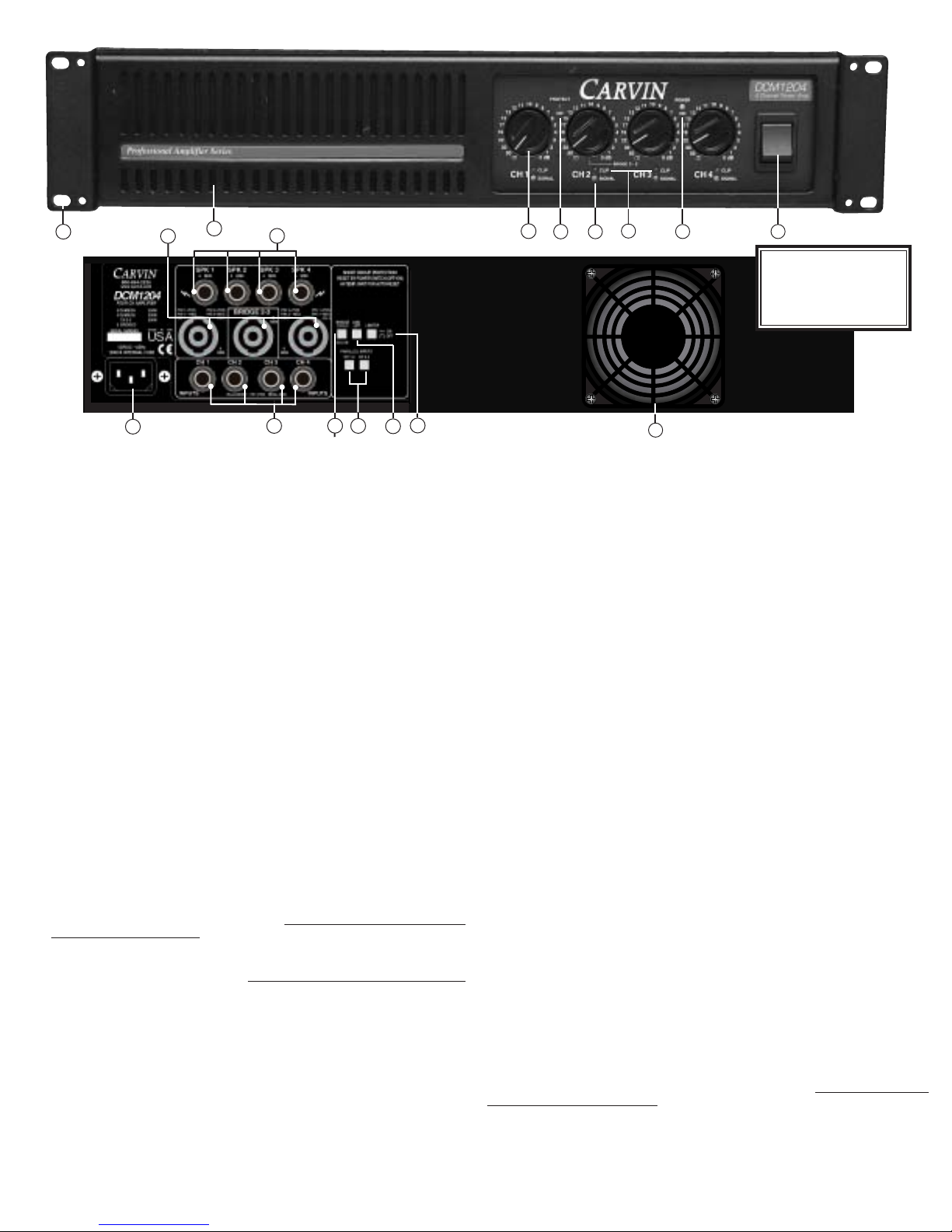
10-01204A 1 EACH FRONT PANEL 2 SPACE DCM 2/4 CH
10-07504 1 EACH FRONT PANEL INSERT 2-RACK SPAC
10-07507A 1 EACH BRACKET FRONT CONTROL DCM/HT
10-82005 1 EACH LID DCM POWER AMPS
10-10008C 1 EACH CHASSIS 2 SPACE UNIVERSAL
15-10172 1 EACH TOROID 120V DCM1000
20-32002 1 EACH CONNECT THRU .100" 22AWG 2 PIN
25-31350 1 EACH SWITCH DPST ROCKER BLACK POWER
76-01204A 1 EACH MANUAL DCM1204
77-12049A 1 EACH LABEL FRONT DCM1204
77-07521 1 EACH LABEL TRIM FACE .250x7.720 BLU
77-01204C 1 EACH LABEL REAR DCM1204
80-01204 1 EACH DCM1204 4 CH power amp
80-01204
03-00220 4 EACH INSLTR MICA .0030".450"X .65"
Q106, Q206, Q506, Q606
03-00450C 1 EACH INSLTR HTSNK 12-01200 SNGL ADH
03-00451B 1 EACH INSLTR HTSNK 12-01200 DBL ADHV
03-00503 13 EACH INSULATOR .36X .36X .20" 85deg
On top of each TO-220 package
03-50135 1 EACH STANDOFF LED .500 X .135 T1 D36
03-92521 10 EACH STANDOFF LED .925 x .215 T1
D26, D33, D34, D103, D203, D27, D29,
D32, D35, D28
06-10028 16 EACH MS PPH 4-40X .500 ZINC TYPE F
06-10032 4 EACH MS PPH 4-40X 1.500 TYPE F ZINC
07-01603 4 EACH KNOB "6L" 6x6x17.4mm GREY CAP
S2, S3, S4, S5
12-01200C 2 EACH HEATSINK 225.6MM SMT 1200W 12
12-57462 2 EACH HEATSINK VERT W/TABS T0-220 VR3, VR4
15-00105 4 EACH COIL AIR 1.5uH 14AWG L1, L2, L100, L200
21-31100 1 EACH RECEPTACLE AC W/FAST-ON CHASS
21-45000 3 EACH SPEAKON 4-POLE PCMTG #NL4MD-V J1, J2, J3
21-52345 4 EACH JACK .250 PHONE MONO STEEL
J101, J201, J501, J601
21-51545 4 EACH JACK .250"PHONE STEREO PLASTIC
J102, J202, J502, J602
23-08604 5 EACH CONNECT HEADER .086" 4 PIN H5A, H5B,
H9B (H9A, H10 SECONDARY BACK SIDE)
23-08609 1 EACH CONNECT HEADER .086" 9 PIN H7
23-10002 5 EACH CONNECT HEADER .100" 2 PIN
H12, Hbias1, Hbias2, Hbias3, HBIAS4
23-11004 6 EACH CONNECT HEADER 4 PIN STRAIGHT
H1A, H1B, H11A, H11B, H12A, H12B
23-11008 4 EACH CONNECT HEADER 8 PIN STRAIGHT
H2A, H2B, H13A, H13B
23-11010 2 EACH CONNECT HEADER 10 PIN STRAIGHT H3A, H3B
25-02201 3 EACH SWITCH DPDT PUSH PC MTG LOCKNG S3,
S4, S5
25-02201-1 EACH ASSEMBLED SWITCH AND CAP S1
25-04201 1 EACH SWITCH 4PDT PUSH PC MTG LOCKNG S2
30-01204B 1 EACH PCB DCM1204
42-10381 4 EACH CAP ELEC 10,000 MFD 80V 20%
C501A, C502, C508, C509
45-56152 8 EACH CAP CERM 560PF 500VOLT 10% C184,
C182, C282, C284, C582, C584, C682, C684
47-10235 3 EACH CAP ELEC 1,000 MFD 35V 20% C503,
C504, C507
47-22151 1 EACH CAP ELEC 220 MFD 50VOLT 10% C9
49-10212 1 EACH 0.001UF SMT 10% FILM 0805 50V C403
49-10312 4 EACH 0.01UF SMT 10% FILM 080550V
C181, C281, C581, C681
49-10451 17 EACH 0.1 uF SMT 10% FILM 1206 50V C3, C4,
C5, C6, C7, C8, C62, C63, C121 C221,
C310, C219, C222, C114, C214, C514, C614
49-12152 8 EACH 120PF SMT 5% CERAMIC 0805 C115, C116,
C215, C216, C515, C516, C615, C616
49-22035 18 EACH SMTCAP 22uF 35v ELECTROLITIC C313, C318,
C120, C220, C520, C620 C110, C111, C118,
C210, C211, C218, C510, C511, C518, C610,
C611, C618
49-27052 8 EACH 27 PF SMT 5% CERAMIC 0805 C113, C213,
C513, C613, C117, C217, C517, C617
49-39052 9 EACH 39PF SMT 5% CERAMIC 0805 C112, C212,
C512, C612, C175, C176, C276, C576, C676
49-47212 1 EACH 0.0047uF SMT FILM 0805 50V C317
49-47312 4 EACH 0.047UF SMT 10% FILM 0805 50V
C180, C280, C580, C680
49-82052 4 EACH 82PF SMT 5% CERAMIC 0805
C177, C277, C577, C677
55-03300 16 EACH RES .33 OHM 5W 5% SB VERT R152, R153,
R154, R155, R252, R253, R254, R255, R562,
R553, R554, R555, R652, R653, R654, R655
56-10025 1 EACH RES 100.00 OHM 10W 10% SB SDOF R2
58-10025 22 EACH 100.5 SMT .25W 1206 1% R1, R114,
R214, R514, R614, R405, R146, R149,
R156, R159, R246, R249, R256, R259,
R546, R549, R556, R559, R646, R649,
R656, R659
58-10035 32 EACH 1K SMT .25W 1206 1% R118, R218, R518,
R618, R637, R642, R643, R644, R645,
R537, R542, R543, R544, R545, R137,
R142,R143, R144, R145, R237, R242,
R243, R244, R245, R318, R325, R135,
R235, R535, R635, R31, R33
58-10045 38 EACH 10K SMT .25W 1206 1% R112, R113,
R212, R213, R512, R513, R612, R613,
R119, R120, R219, R220, R519, R520,
R619, R620, R177, R277, R577, R677,
R320, R324, R336, R337, R130, R131,
R126, R226, R526, R626, R123, R124,
R223, R224, R523, R524, R623, R624,
58-10055 14 EACH 100K SMT .25W 1206 1% R178, R179,
R278, R279, R331, R578, R579, R678,
R679, R32, R125, R225, R525, R625
58-15025 4 EACH 150ohm SMT .50W 1206 1%
R148, R248, R548, R648
58-15035 1 EACH 1.5K SMT .25W 1206 1% R312
58-15045 8 EACH 15K SMT .25W 1206 1% R121, R122,
R221, R222, R521, R522, R621, R622
58-15055 8 EACH 150K SMT .25W 1206 1% R102, R202,
R502, R602, R132, R232, R532, R632
58-18035 1 EACH 1.8K SMT .25W 1206 1% R315
58-22025 1 EACH 220.5 SMT .25W 1206 1% R3
58-22035 8 EACH 2.2K SMT .25W 1206 1% R100, R101,
R133, R233, R500, R533, R600, R633
58-22045 3 EACH 22K SMT .25W 1206 1%
R319, R317, R327
58-22055 1 EACH 220K SMT .25W 1206 1% R9
58-27045 1 EACH 27K SMT .25W 1206 1% R323
58-33035 2 EACH 3.3K SMT .25W 1206 1% R309, R329
58-33045 4 EACH 33K SMT .25W 1206 1%
R104, R204, R504, R604
58-47025 4 EACH 470.5 SMT .25W 1206 1%
R140, R240, R540, R640
58-47035 19 EACH 4.7KSMT .25W 1206 1% R134, R139, R141,
R234, R239, R241, R326, R534, R539, R541,
R634, R639, R641, R30, R200, R128, R228,
R528, R628
58-47045 10 EACH 47K SMT .25W 1206 1% R176, R276,
R576, R314, R311, R138, R238, R538,
R676, R638
58-47055 14 EACH 470K SMT .25W 1206 1% R322, R10, R127,
R227, R527, R627 R115, R116, R215, R216,
R515, R516, R615, R616
58-56035 1 EACH 5.6K SMT .25W 1206 1% R321
58-68025 4 EACH 680 SMT .25W 1206 1%
R147, R247, R547, R647
58-68045 1 EACH 68K SMT .25W 1206 1% R330
58-92201 28 EACH 22 SMT 1W 2512 20% R5, R6, R11, R12,
R13, R14, R15, R16, R550, R551, R23,
R25, R26, R27, R650, R651, R136, R150,
R151, R182, R332, R333, R334, R335,
R250, R251, R419, R420
60-31000 4 EACH BIPOLAR PWR TIP31C NPN 3A 100V
Q106, Q206, Q506, Q606
60-21193A 8 EACH TRNS PWR MJW21193 PNP TO-247 Q114,
Q116, Q214, Q216, Q514, Q516, Q614, Q616
60-21194A 8 EACH TRNS PWR MJW21194 NPN TO-247 Q110,
Q115, Q210, Q215, Q510, Q515, Q610, Q615
60-15032 4 EACH TRANS MJE15032 NPN T0-220
Q107, Q207, Q507, Q607
60-15033 4 EACH TRANS MJE15033 PNP T0-220
Q111, Q211, Q511, Q611
60-35041 1 EACH RECTIFIER BRIDGE 35AMP/400V PC
60-50253 4 EACH OPTO ISOLATOR VACTROL AXIAL
OP100, OP200, OP500, OP600
60-75320 6 EACH LED RED DIFFUSED 3MM T-1.00 D28, D33,
D34, D103, D203 (ALL WITH STANDOFF)
D36 WITH 03-50135 STANDOFF
60-75330 4 EACH LED GREEN DIFFUSED 3MM T-1.00
D27, D29, D32, D35 (ALL WITH STANDOFF)
60-75340 1 EACH LED YELLOW DIFFUSED 3MM T-1.00
D26(WITH STANDOFF)
60-78150-1 EACH REG VOLT 15+V 1A (PREPPED) VR3
60-79120-1 EACH REGULATOR VOLTAGE 12 (PREPPED) Q7
60-79150-1 EACH REG VOLT 15-V 1A (PREPPED) VR4
62-00014 1 EACH MMBTA14 SOT-23 SMT Q4
62-06001 14 EACH DIODE ULTRA FAST 600V 1A SMA D108, D109,
D208, D209, D501B, D502B, D503B, D504B,
D505B, D506B, D508, D509, D608, D609
62-19140 38 EACH 1N914 HI SPD SMT 250mW DIODE D2, D3,
D5, D6, D7, D8, D9, D10, D11, D12, D13,
D14, D15, D16, D17, D19, D106, D107,
D111, D206, D207, D310, D311, D312,
D506, D507, D606, D607, D1, D4, D25,
D18, D20, D21, D22, D100, D30, D31
62-03400 5 EACH TRANSISTOR SMT MJD340
Q105, Q205, Q301, Q505, Q605
62-03500 4 EACH TRANSISTOR SMT PNP MJD350 Q104,
Q204, Q504, Q604
62-20430 7 EACH NJM2043SMT(TESTED) DUAL HFREQ
A100, A200, A500, A102, A202, A502, A602
62-29010 2 EACH NJM2901SMT QUAD COMP A1, A2
62-45650 6 EACH NJM4565 SMT DUAL HI FREQ
A20, A21, A101, A201, A501, A601
62-54001 10 EACH MMBT5401LT1 PNP SOT-23 SMT
Q117, Q217, Q303, Q517, Q103, Q203,
Q503, Q304, Q603, Q617
62-55500 10 EACH MMBT5550 NPN SOT-23 Q2, Q10, Q9,
Q302, Q17, Q102, Q202, Q502, Q14, Q602
70-02408A 1 EACH FAN DC24V 80mm X 80mm X 25mm 4
70-05710 5 EACH RELAY SPDT 12A@120VAC/24V COIL
K1, K100, K200, K300, K400
70-22125 1 EACH FUSE MDA 25.00A SLOW 6.35X32MM F1
71-09221 4 EACH POT 9 D-P B10K 21 DETENT
P100, P200, P500, P600
71-24500 4 EACH POT VERT TRIMMER 500ohm PHILL
P101, P201, P501, P601
REPLACEMENT PARTS LIST
Table of contents
Other CARVIN Amplifier manuals

CARVIN
CARVIN QUADX User manual

CARVIN
CARVIN V3M User manual

CARVIN
CARVIN DCM200L User manual

CARVIN
CARVIN VL300 User manual

CARVIN
CARVIN Belair212 User manual

CARVIN
CARVIN DCM2000 User manual

CARVIN
CARVIN PB200 II User manual

CARVIN
CARVIN DCM4000 User manual

CARVIN
CARVIN F150 User manual

CARVIN
CARVIN Tube 100 User manual

CARVIN
CARVIN F1200 User manual

CARVIN
CARVIN DCM4000 User manual

CARVIN
CARVIN DCM1540L User manual

CARVIN
CARVIN F600 User manual

CARVIN
CARVIN KB1000 User manual

CARVIN
CARVIN DCM1015 User guide

CARVIN
CARVIN R600 Red Line Series User manual

CARVIN
CARVIN Legacy drive vld1 User manual

CARVIN
CARVIN Vintage 16 User manual

CARVIN
CARVIN DCM1001 User manual