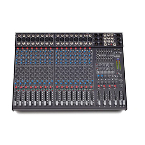
JACKS
These LINE inputs are 1/4” phone jacks designed for unbalanced line and
instrument level inputs. Examples of these inputs would be instruments
such as a guitar, a keyboard, an unbalanced mic, or multi track outputs. If
a mono input is needed, use the left input jack and the channel will act like
a mono channel with a normal functioning pan going to L/R masters.
10. GAIN SWITCHES
The gain switches boost the line level at the stereo channels (11-16) by
+12db. This is ideal for stereo sources that may be too weak.
11-15 MASTER CONTROLS
11. L/R MASTER CONTROL+USB OUTSOURCE
The L/R master control is the master volume control for the left - right
stereo mix. This control receives its signals from the channel pan controls
and generates the volume heard in the left and right main output jacks.
12. CONTROL ROOM
The CONTROL ROOM level controls the volume for the headphone jack
and speaker jacks. The signal going out to the headphones and speaker
is controlled by the TAPE IN/USB switch.
13. TAPE IN/USB SWITCH
This switch controls the Main L/R signal going to the Control Room as
well as the Tape IN/USB signal to the Main L/R out. In the UP position,
the Main L/R is connected to the Control Room, and the Tape IN/USB
is connected to the Main L/R. In the DOWN position, the Main L/R is
no longer connected to the Control Room and the Tape IN/USB is con-
nected to only the Control Room. This is used for Tracking, or recording
an individual track at a time while still allowing you to monitor playback
through the Control Room.
14. SEND 1 AND 2 CONTROLS
The SEND 1 and SEND 2 master controls are the levels for the EFF 1 and
EFF 2 sends from the channels. The output of these controls are available
at the effects send 1 and 2 output jacks. The typical use of effects sends
is to drive external effects processors, but it can also be used as another
stage monitor mix or headphone mix if needed.
15. EFFECTS RETURN 1AND 2 CONTROLS
The RETURN 1 and RETURN 2 controls are stereo effects return controls.
They receive input from the LEFT and RIGHT 1/4” EFFECTS RETURN jacks
in the master section. These control the return level going to the master
left right stereo mix. A mono return into the stereo mix can be achieved
by simply feeding the mono signal into the left return jack. These stereo
returns can also be used as another input to the stereo mix for a keyboard
or other stereo and mono gear.
16. TAPE IN CONTROL + USB IN
The TAPE IN control is a stereo tape return level. It receives its input
from the L/R TAPE RTN RCA jacks. This volume controls the level feed-
ing the master L/R stereo mix. A mono TAPE IN into the stereo mix can
be achieved by simply feeding the mono signal into both Left and right
RCA jacks. The stereo TAPE IN can also be used as another input to the
stereo mix for a keyboard or other stereo gear.
17-26 MASTER CONNECTORS
17. STEREO EFFECTS RETURN 1 AND 2
JACKS
The stereo EFFECTS RETURN 1 and 2 jacks are the input jacks for the
stereo return 1 and 2 master RETURN.
18. EFFECTS SEND 1 AND 2 JACKS
The EFFECTS SEND 1 and 2 jacks are the output jacks to feed your effects
or monitors. These sends are controlled by the master SENDS 1 & 2.
19. LEFT AND RIGHT LINE OUT JACKS
The LEFT and RIGHT LINE OUT are 1/4” unbalanced output jacks. The
same signals are also being fed to the TAPE OUT RCA jacks and XLR
outs.
20. XLR OUTPUTS
The L/R XLR outputs allow for professional balanced connections.
21. TAPE OUT AND TAPE IN RCA JACKS
The LEFT/RIGHT TAPE OUT RCA jacks deliver the main left - right
stereo
output for recording.
The LEFT/RIGHT TAPE IN jacks are RCA inputs, To the TAPE IN level
control adjust the input level and adds it to the mix.
The TAPE IN jacks can also be used for returning another effects processor
or instrument such as a keyboard to the main mix.
The RCA jacks are Ideal for using a cassette deck to record a mix using
the TAPE OUT jacks and playing it back through the TAPE IN jacks with
out using up any channels for play back or having to use adapters to
hook up the cassette deck.
22. POWER LED
The Power LED indicates when the mixer is powered up.
23. PHANTOM POWER SWITCH AND LED
The PHANTOM power switch turns on the microphone phantom power
in the 8 MIC/LINE channel XLR jacks. The phantom power is used for
supplying a bias voltage to condenser microphones. The LED indicates
the phantom power is turned on. The phantom power will not damage
dynamic microphones.
24. AC POWER & FUSE
The detachable AC POWER CORD supplied is designed to operate with one
type of voltage (the European 230V export model uses a CEE-7 plug cord
set). Plug the cord into a grounded “3 prong” power source. No attempt
should ever be made to use the amp without the ground connected.
The FUSE is located within the mixer. The fuse type is a 250V 5 x 20
mm 3 AMP. The fuse is not normally a user serviceable part. If the mixer
doesn’t turn on and there is power at the AC cord and the cord is firmly
connected, then service is required.
25. POWER SWITCH
ON/OFF control.
26. HEADPHONES
Use a high quality stereo headphone simular to Carvin’s H40M.
27. SPEAKER OUTPUTS
L-R Speaker out (8Ωmin, 22w per channel). Use to monitor main record-
ing mix or for low power PA use.
28. USB & S/PDIF
Connecting a USB cable between a computer and the S16 mixer
will allow recording on a computer with compatible USB drivers
and software. The L-R stereo mix is sent via the USB cable
and the RECORD LEVEL offers fine tuning of the output level.
Inversely, you can bring audio in from computer playback via
USB. The audio comes into the TAPE IN bus on the mixer, see
#13 TAPE IN/USB switch. The S/PDIF connector can be used
to bring in digital audio to a computer through USB. This is
useful for transferring digital audio sources such as DAT to
the computer. It can also be used to convert playback from
the computer into S/PDIF out. This is useful for creating a
digital backup of computer recorded audio to another digital
recorder. The USB and S/PDIF feature up to 48kHz, 16 BIT
audio resolution.
21
11
12
16
14
15
20
22
S16 REAR PANEL
17
18
19
26
10
9
QUICK START UP
If you’re like most new owners, you’re probably in a hurry to plug your
mixer in and use it. Here are some brief instructions to get you going
quickly. With the mixer unplugged and the unit turned off, complete the
following procedures:
1. CONNECTING AC POWER TO YOUR MIXER
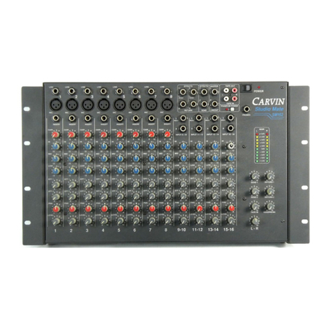
• Studio Mate will except line voltages 100 ~250VAC. (USA
120VAC,
Europe 240 VAC ...etc.)
• Use only a grounded (3 prong) power outlet to prevent a shock
hazard.
This gives the quietest grounding for your mixer.
• Insert power cord. Be sure it’s pushed all the way in.
2. TURNING YOUR MIXER ON
• Adjust all channel and master level controls to their off positions
(fully counter clockwise).
• Adjust all “EQ” tone controls— the channel’s Hi, Mid, and Bass
controls to their center position.
• Adjust all the Channel “PAN” controls to their center position.
• Turn the mixer on by the rear panel power switch and watch for
the
power LED to come on. Your mixer is now ready to operate.
3. CONNECTING INPUTS TO YOUR MIXER
• For low level balanced devices such as microphones, plug into
the
balanced MIC inputs using a shielded microphone cable with XLR
ends.
• For high level unbalanced devices such as Tape Recorders and
Keyboards, plug into the LINE input jacks using a shielded cable
with
1/4” phone ends.
1-8 MIC CHANNEL FEATURE
1. LINE INPUT JACK
The LINE input is a 1/4” phone jack designed for unbalanced line and
instrument level inputs. Examples of these inputs would be instruments
such as a guitar, a keyboard, an unbalanced mic, or a pre-amp output. The
line input can be used at the same time the mic input is being used.
2. XLR MICROPHONE INPUT
The XLR MIC input is designed for balanced low impedance microphone
s. The XLR connector is wired as per the industry standard where pin
1 is ground, pin 2 is non-inverting (positive), and pin 3 is inverting
(negative).
Phantom power is available on every XLR input jack when the phantom
power switch above channel 8. This feature allows condenser micro-
phones to be run directly from the mixer.
Note: When using phantom power, make sure the phantom power is
switched off before connecting or disconnecting microphones to the
mixer. It is recommended to allow 5 seconds for the phantom power
to discharge before making any microphone connections. Also, to
avoid hearing a pop, turn down the main volume when turning on the
phantom power.
3. INSERT JACK
The insert jack is a Tip Ring Sleeve (TRS) 1/4” jack where the tip is the
send, the ring is the return and the sleeve is ground. The insert point
is after the input (MIC-pre) amplifier and before the channel EQ section
(see the Block Diagram page 9 ). When a 1/4” plug is fully inserted it
breaks the connection between the mic-pre and the channel EQ. This,
insert break -point, allows external equipment to be used on only the
channel it is inserted into. One common use is to insert a compressor.
This will reduce any input spikes before they distort the channel’s EQ or
the master busses.
Another use for the insert jack, is a direct output. To achieve this func-
tion, insert a mono 1/4” plug into the first click of the jack. The result
is a direct output signal from the channel that does not disturb the
channels operation. A common use for the insert direct out is in multi
tracking when individual channels are recorded to separate tracks on a
multi track recorder.
4. GAIN CONTROL
The gain control adjusts the input gain on both the line and mic input jacks.
For the mic input, the gain range goes from a +3dB min to +49dB. For the
line input, the gain goes from a -12dB min to +34dB. For optimum signal
to noise performance, the gain control should be set for the highest level
possible before distortion or clipping of the incoming signal. In order to
reduce surprise feedback and other thumps start, with the gain control at
minimum. If distortion is heard regardless of the position of the channel
LEVEL control, lower the gain control until no distortion is heard.
5. CHANNEL TONE CONTROLS
Each channel features three tone controls LO, MID, and HI. All three
controls function as boost /cut controls, where the center “0” position
neither boosts nor cuts. For boosting, turn the control clockwise and for
cutting, turn the control counterclockwise. The LO and HI controls are
shelving type tone controls with corner frequencies at 80Hz and 11.5k Hz
respectively. The shelving means for the LO control all the bass frequen-
cies from 90Hz and down. For the HI control, the shelving means all the
HI frequencies from 11.5k Hz and up will be affected. The MID control is
a band pass type of tone control. The band pass means a middle section
of frequencies centered around 2.2kHz, but do not over-lap the HI and
LO controls. The MID affects the clarity of the average person’s spoken
voice. Also the MID controls the louder sometimes harsher tones that can
distort the over all sound. Use these controls to change the tonal shape
of the input signal and in many cases to reduce possible feedback in live
situations. It is suggested the channel tone controls start out in their center
detente positions where they do not affect the original incoming signal.
Then, if needed, adjust the tone controls to change the sound.
6. CHANNEL EFFECTS 1 AND EFFECTS 2
These controls are identical in function. Both adjust the volume of the
channel going to the effects send master controls. The only difference
is EFF 1 goes to Send 1 and EFF 2 goes to Send 2. Both controls are
post channel level. This means adjustments in the channel’s EQ or level
controls will effect the sound and volume of the EFF 1 and EFF 2 sends.
7. CHANNEL PAN CONTROL
The PAN control adjusts where the channel is heard in the stereo field
of the stereo master outputs. If it is turned to the extreme left, then the
channel will only be heard in the left master output and similarly only in
the right master output if turned to the extreme right. In the center posi-
tion the channel is heard equally in both the left and right main outputs.
A good starting point for the pan is in the center position. Then if stereo
placement is needed, a quarter turn to the desired side from the center
position gives a smooth placement in the stereo field, or if desired a full
turn to one side assigns the channel to the L or R.
8. CHANNEL LEVEL CONTROL
The LEVEL control adjusts the final volume of the channel before going to
the Pan control. Here is where the individual channel volumes are adjusted
to make up the desired mix heard at the master left and right outputs.
9-10 STEREO LINE CHANNEL FEATURES
9. CH 9 THRU 16 LEFT/RIGHT LINE INPUT
S16 PANEL CONTROLS
1
2
3
4
7
8
23
5
24
6
25
S16
13
27 28
