CARVIN PRO-MIX 7 User manual

The PRO-MIX-7 is designed for the DJ who requires professional mixing with the flexibility of
7 channels plus sound effects. High-end electronics feature ultra low noise circuitry and SMT
construction giving a crystal clear transparent sound that rivals our larger consoles offering a
notch of performance above the typical DJ mixer.
FEATURES:
• 4 stereo channels with transform switches for any combination of 3 vinyl and 5 CD/line
inputs
• 3 Mic channels for vocals and other sources with TALKOVER feature
• Active LO, MID and HI EQs on each channel are set at 80, 750 and 11.5 k Hz
• 25 dB EQ cuts on the 4 main channels
• Input GAIN controls on each channel prevent overloading
• 4 segment metering for each main channel, plus 10 segment MASTER metering
• Each of the four main channels are assignable to either side of the A/B CROSSFADER
• 24-BIT effects with Reverb, Echo, Chorus and Flange are assignable to either side of the
A/B CROSSFADER or 3 MIC channels, with bypass switch. All parameters are easily
changed for rate, damping, decay, depth, time and regeneration.
AUX OUTPUTS include a separate ZONE for MASTER or MONITOR mix, and a MONO
output which can be switched into a SUBWOOFER output utilizing an internal 150 Hz, 18 dB
per octave crossover. Both outputs have separate level controls.
The MONITOR control center takes it’s input from the MONITOR MIX control for critical listen-
ing of the MASTER output and CUE monitoring from of any of the 4 MAIN or 3 MIC channels.
The MONITOR LEVEL control drives the powerful built in headphone amp, delivering high vol-
ume levels to all 3 headphone outputs.
SUPERB SOUND is derived from the extremely low distortion, high "Headroom" design.
A state-of-the art, low noise, balanced XLR mic preamp for each channel features a common
mode rejection of better than 78 dB, which means that any possible noise that may come over
your cables is virtually eliminated. Even the balanced XLR output connectors guard your sys-
tem from cable noise. Distortion is nearly non-existent with THD below .01%, which guaran-
tees the purity of your sound. Hear the difference - your sound will not seem "sterile" or
"processed". It will be dynamically open and transparent just like it was meant to be!
EASY TO USE Everything is logically laid out making the PRO-MIX 7 simple to use, which
helps to eliminate operator error.
24-Bit STEREO DSP EFFECTS The effects processor with 256 EFFECTS, include
reverbs, choruses, flanging and echoes, with parameters fully adjustable for; damping, decay,
depth, speed, regeneration and time.
ACTIVE 3 BAND CHANNEL EQ Provides easy adjustment for the tone you want. The
LO frequency controls starts at 20 Hz and continues through 80 Hz for adding solid non-flab-
by bass. A simple adjustment with the MID band, gives you the best sound for vocals or gui-
tar in the very important 750Hz frequency range. The 11.5k Hz HI treble control adds sparkle
to your top-end without adding harshness. Both the LOW and HI are "shelving", which means
they are effective from 20Hz up to 20k Hz.
ENGINEERED TO LAST Every PRO-MIX 7 mixer incorporates a rugged reinforced steel
chassis. Hidden deep in the heart of these mixers is the “SMT” Surface Mount Technology
construction that utilizes surface mounted components to prevent parts from shaking or
vibrating loose. Sealed controls and switches guard against the outside elements while heavy-
duty connectors provide a positive connection to your cables. Fire retardant FR-4 military
spec. circuit cards feature double-sided copper construction to guard against noise and radio
frequencies (RF). Precision 1% tolerances guarantee that your settings will be accurate every
time. The PRO-MIX 7 is professionally made in the USA for years of service!
76-27001 021004
PRO-MIX 7 SPECIFICATIONS:
FREQUENCY RESPONSE: Mic or Line Inputs: 20 to 20k Hz,
OUTPUT: +26dB XLR bal, +20dB RCA unbal
TOTAL HARMONIC DISTORTION: Less than .01% at nominal levels
EQUIVALENT INPUT NOISE: 150 ohm source: -117dBu
INPUTS:3equalized RIAA PHONO RCA inputs,
with ground terminal
5 LINE RCA inputs
3 MIC inputs: balanced XLR and 1/4” jacks
MASTER: balanced XLR, 2 pair RCA jacks
MONO/SUB: balanced XLR
ZONE: balanced 1/4” jack
PHONES: 1/4” jack, stereo
MONITOR: 1/4” jacks, 1 stereo, 1 mono
OUTPUT NOISE: -90dBu Master Out
CROSSTALK: Adjacent ch’s: -60db at 1KHz
COMMON MODE REJECTION: -78db at 1KHz
CHANNEL EQ 3-BAND ACTIVE:
LOW: 80Hz
MID: 750Hz
HI: 11.5KHz
POWER REQ.: 90 to 250 VAC 50-60Hz, internal switching
power supply
SIZE AND WEIGHT: 19” x 8.5” x 3.5” D. (5U rack mount) Wt. 15 lbs.
CAUTION
RISK OF ELECTRIC SHOCK
DO NOT OPEN
SAFETY INSTRUCTIONS (EUROPEAN)
The conductors in the AC power cord are colored in accordance with the following code.
GREEN & YELLOW—Earth BLUE—Neutral BROWN—Live
U.K. MAIN PLUG WARNING: A molded main plug that has been cut off from the cord is
unsafe. NEVER UNDER ANY CIRCUMSTANCES SHOULD YOU INSERT A DAM-
AGED OR CUT MAIN PLUG INTO A POWER SOCKET.
IMPORTANT! FOR YOUR PROTECTION, PLEASE READ THE FOLLOWING:
WATER AND MOISTURE: Appliance should not be used near water (near a bathtub, washbowl,
kitchen sink, laundry tub, in a wet basement, or near a swimming pool, etc). Care should be taken
so that objects do not fall and liquids are not spilled into the enclosure through openings.
POWER SOURCES: The appliance should be connected to a power supply only of the type
described in the operating instructions or as marked on the appliance.
GROUNDING OR POLARIZATION: Precautions should be taken so that the grounding or polar-
ization means of an appliance is not defeated.
POWER CORD PROTECTION: Power supply cords should be routed so that they are not likely to
be walked on or pinched by items placed upon or against them, paying particular attention to
cords at plugs, convenience receptacles, and the point where they exit from the appliance.
SERVICING: The user should not attempt to service the appliance beyond that described in the
operating instructions. All other servicing should be referred to qualified service personnel.
FUSING: If your unit is equipped with a fuse receptacle, replace only with the same type fuse.
Refer to replacement text on the unit for correct fuse type.
REFER SERVICING TO QUALIFIED SERVICE
PERSONNEL! THIS UNIT CONTAINS HIGH
VOLTAGE INSIDE!
CAUTION
RISK OF ELECTRIC SHOCK
This symbol is intended to
alert the user to the pres-
ence of uninsulated “dan-
gerous voltage” within the
product’s enclosure that
may be of sufficient magnitude to constitute
a risk of electric shock to persons.
This symbol is intended
to alert the user to the
presence of important
operating and mainte-
nance (servicing)
instructions in the literature accompany-
ing the appliance.
LIMITED WARRANTY
Your Carvin product is guaranteed against failure for 1 YEAR unless otherwise stated.
Carvin will service and supply all parts at no charge to the customer providing the unit is
under warranty. Shipping costs are the responsibility of the customer. CARVIN DOES NOT
PAY FOR PARTS OR SERVICING OTHER THAN OUR OWN. A COPY OF THE ORIGINAL
INVOICE IS REQUIRED TO VERIFY YOUR WARRANTY. Carvin assumes no responsibility
for horn drivers or speakers damaged by this unit. This warranty does not cover, and no
liability is assumed, for damage due to: natural disasters, accidents, abuse, loss of parts,
lack of reasonable care, incorrect use, or failure to follow instructions. This warranty is in
lieu of all other warranties, expressed or implied. No representative or person is authorized
to represent or assume for Carvin any liability in connection with the sale or servicing of
Carvin products.
CARVIN SHALL NOT BE LIABLE FOR INCIDENTAL OR CONSEQUENTIAL
DAMAGES.
When RETURNING merchandise to the factory, you may call for a return authorization
number. Describe in writing each problem. If your unit is out of warranty, you will be
charged the current FLAT RATE for parts and labor to bring your unit up to factory spec-
ifications.
MAINTAINING YOUR EQUIPMENT
Avoid spilling liquids or allowing any other foreign matter inside the unit. The panel of
your unit can be wiped from time to time with a dry or slightly damp cloth in order to
remove dust and bring back the new look.
As with all pro gear, avoid prolonged use in
caustic environments (salt air). When used in such an environment, be sure the mixer
is adequately protected by a cover.
CARVIN ENGINEERING DATA OPERATING MANUAL
PRO-MIX 7 DJ MIXER
c
PHONOLINEOUT
LEFTMONO/SUB
MASTER OUTPUTS
L
R
RIGHT
321
MONITOR
(PHONES)
MONITOR
(MONO)
MASTER
OUT
REC
L
R
L
R
L
R
L
R
PHONO PHONOLINE
ZONE
(MONO)
2
MIC 2 MIC 1MIC 3
PRO-MIX 7PRO-MIX 7
AUS
MADE IN THE
S/N XXXXXXX
www.carvin.com
90 - 250 VAC 50/60Hz 30VA
1-800-854-2235
4LINE
INTERNAL FUSE
ON
LINE
5
LINE
4
PROTECT
50
30
22
19
17
15
13
1211 10 98
7
6
5
4
3
2
1
0 dB
DCM2000
1000WattPowerAmp
CLIP
SIGNAL
50
30
22
19
17
15
13
1211 10 98
7
6
5
4
3
2
1
0 dB
0 dB
POWER
CHANNELONE CHANNELTWO
CLIP
SIGNAL
PROTECT
50
30
22
19
17
15
13
1211 10 98
7
6
5
4
3
2
1
0 dB
DCM2000
1000WattPowerAmp
CLIP
SIGNAL
50
30
22
19
17
15
13
1211 10 98
7
6
5
4
3
2
1
0 dB
POWER
CHANNELONE CHANNELTWO
CLIP
SIGNAL
PROTECT
50
30
22
19
17
15
13
1211 10 98
7
6
5
4
3
2
1
0 dB
DCM2000
1000WattPowerAmp
CLIP
SIGNAL
50
30
22
19
17
15
13
1211 10 98
7
6
5
4
3
2
1
0 dB
POWER
CHANNELONE CHANNELTWO
CLIP
SIGNAL
PROTECT
50
30
22
19
17
15
13
1211 10 98
7
6
5
4
3
2
1
0 dB
DCM2000
1000WattPowerAmp
CLIP
SIGNAL
50
30
22
19
17
15
13
1211 10 98
7
6
5
4
3
2
1
0 dB
POWER
CHANNELONE CHANNELTWO
CLIP
SIGNAL
DIRECTDRIVE
TURNTABLESYSTEM
0
+
-
33 45
DIRECTDRIVE
TURNTABLESYSTEM
0
+
-
33 45
DUALCD PLAYER
POWER
OPEN/CLOSE
CD2020
CD1
DUALCD PLAYER
OPEN/CLOSE
REV FWD
PITCHCONTROL
8%,12%,16%
-SEAMLESSLOOP-
PLAY/PAUSE
TRACKSKIP
RELAY
SHUTTLEJOG
CD1
0
+
-
CD2
OPEN/CLOSE
REV FWD
PITCHCONTROL
8%,12%,16%
-SEAMLESSLOOP-
PLAY/PAUSE
TRACKSKIP
RELAY
SHUTTLEJOG
CD1
0
+
-
CD2020
CAUTION
RISK OF ELECTRIC SHOCK
DO NOT OPEN
CAUTION - TO PREVENT ELECTRICAL SHOCK DO NOT DEFEATTHE SAFETY
GROUND ON THE POWER CORD - DO NOT REMOVE COVER .
WARNING - TO PREVENT FIRE OR SHOCK HAZARD DO NOT EXPOSE TO RAIN
OR MOISTURE. REFERSERVICING TO QUALIFED PERSONNEL.
PRO-MIX 7 DJ MIXER
SETUP
RECEIVING INSPECTION—read before getting started
INSPECT YOUR UNIT FOR ANY DAMAGE which may have occurred during shipping.
If any damage is found, please notify the shipping company and CARVIN immediately.
SAVE THE CARTON & ALL PACKING MATERIALS. In the event you have to re-ship your
unit, always use the original carton and packing material. This will provide the best pos-
sible protection during shipment. CARVIN and the shipping company are not liable for
any damage caused by improper packing.
SAVE YOUR INVOICE. It will be required for warranty service if needed in the future.
SHIPMENT SHORTAGE. If you find items missing, they may have been shipped sep-
arately. Please allow several days for the rest of your order to arrive before inquiring.
RECORD THE SERIAL NUMBER on the enclosed warranty card for your records. Keep
your portion of the card and return the portion with your name and comments to us.
USA customers register online at: www.carvin.com/registration
All other countries register online at: www.carvinworld.com/registration
Promix7-manual.qxd 11/2/04 4:31 PM Page 2

QUICK START UP
If you’re like most new owners, you’re probably in a hurry to
plug your mixer in and use it. Here are some brief instruc-
tions to get you going quickly. With the mixer unplugged and
the unit turned off, complete the following procedures:
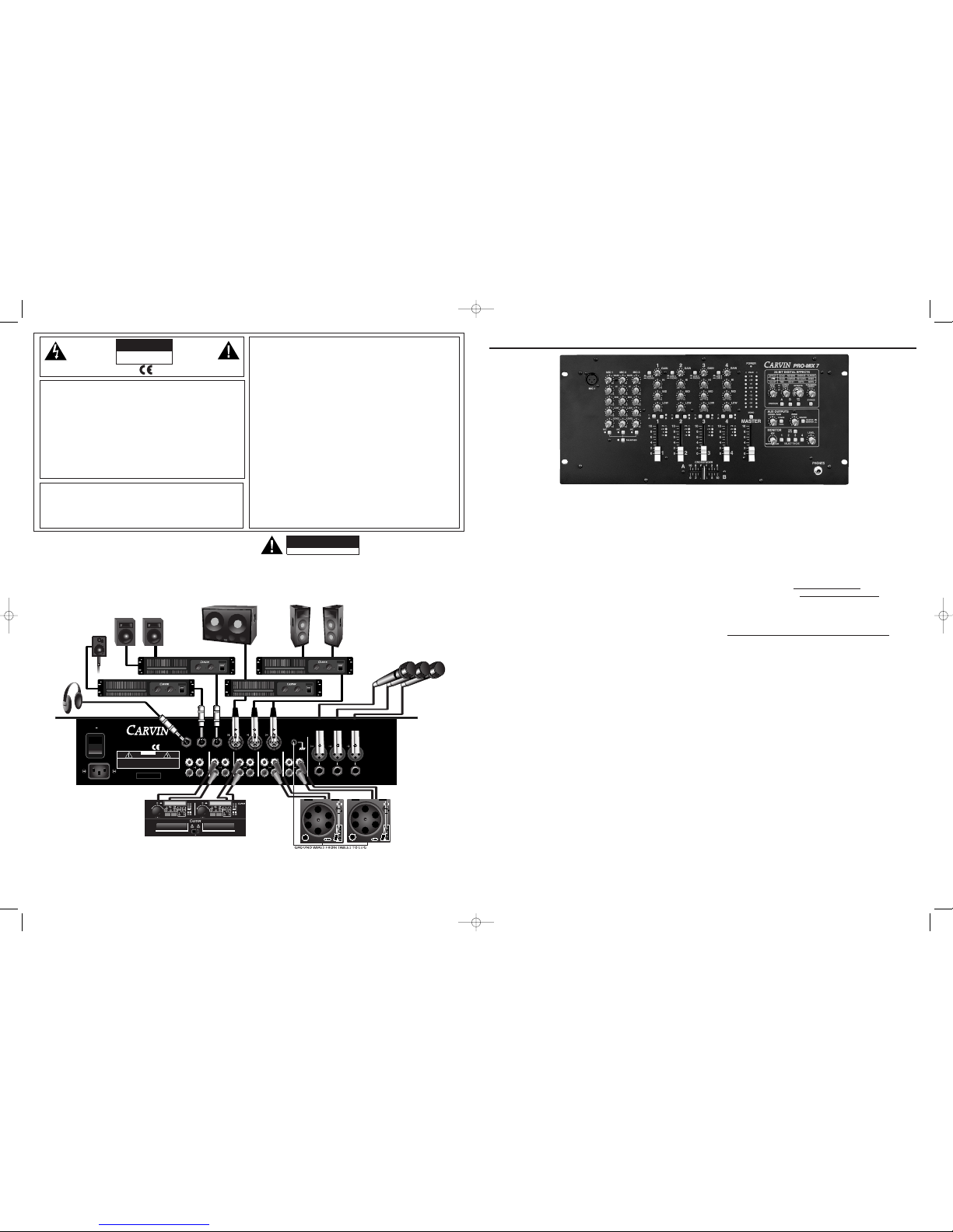
A. CONNECTING AC POWER TO YOUR MIXER
• Be sure to plug your mixer into the proper voltage for your
country, either 120V-60Hz or 240V-50Hz. The Pro-Mix 7
accepts both voltages listed.
• Use only a grounded (3 prong) power outlet to prevent a
shock hazard. This gives the quietest grounding for your
mixer.
B. CONNECTING INPUTS TO YOUR MIXER
• The RCA Phono inputs are for turntables ONLY!
• For CD players and similar devices, use the RCA LINE inputs.
Connecting other inputs will sound distorted.
• For balanced microphones, use a shielded cable and plug
into the XLR MIC inputs.
C. TURNING YOUR MIXER ON
•Set all channel and master LEVEL controls to their OFF
positions
•Set all HI, MID, and LOW controls to their center “flat -
no boost or cut” position.
• Turn the mixer on by the rear POWER SWITCH and watch
for the front POWER LED to come on. Your mixer is now
ready to operate by turning the levels up.
MIC CHANNEL
1. MIC GAIN CONTROL: The mic GAIN control
adjusts the level of the signal from the XLR and 1/4” MIC
input jacks. With the MIC LEVEL and MASTER controls at
“5” and the MIC switch “IN”, turn the GAIN control clock-
wise until the master METERS read about “0dB”. For an
average microphone, start with the GAIN at “5” and
increase. For other inputs such as a keyboard or sampler,
start with the GAIN at “2”. If the sound becomes distorted
or fuzzy, reduce this level until a clear signal is heard. When
this control is adjusted properly, it usually won’t need to be
adjusted for the remainder of the performance.
2. MIC TONE CONTROLS: Each MIC channel is
equipped with three tone controls: HI, MID, and LOW.
These are active EQ circuits that will boost or cut certain fre-
quencies of the MIC input by +or -15dB. The HI control
effects treble frequencies, peaking at 11.5kHz. The MID con-
trol effects mid-band frequencies, centered at 750Hz. The
LOW control adjusts bass frequencies, peaking at 80Hz.
3. MIC LEVEL CONTROL: This control adjusts the
level of the mic for mixing to the main output.
4. MIC ON SWITCH and LED: Pushing this switch
to the “IN” position will activate the MIC channel, allowing it
to be heard at the MASTER outputs. A lit LED shows the
channel is active.
5. TALKOVER SWITCH and LED: Pushing this
switch to the “IN” position lowers the level of music from
main channels 1-4, but leaves the microphone levels at nor-
mal. This will allow the MICS to be heard over the music
while making announcements, etc. A lit LED shows that
TALKOVER is active.
MAIN CHANNELS
6. LINE/PHONO SWITCH: This switch selects one
of two RCA inputs for the channel. It is also known as a
“TRANSFORM” switch. The “OUT” position selects the cor-
responding LINE input on channels 1-4. The “IN” position
selects the corresponding PHONO input on channels 1-3,
and LINE 5 input on channel 4.
7. GAIN CONTROL: For main channels 1-4
The channel GAIN control adjusts the level of the signal from the
selected LINE or PHONO input. If the sound becomes distorted
or fuzzy, reduce this level until a clear signal is heard. When this
control is adjusted properly, it usually won’t need to be adjusted
for the remainder of the performance. (see also #11)
8. CHANNEL TONE CONTROLS: Each of the main
channels are equipped with specialized tone controls: HI,
MID, and LOW. These are active EQ circuits that will boost
+15dB or cut -25dB. The accelerated cut of -25dB allows
you to “TURN DOWN” certain elements of a music track
until they are nearly inaudible. The HI control peaks
11.5kHz, affecting elements such as cymbals and bells. The
MID control is centered at 750Hz and affects elements such
as vocals and guitars. The
LOW control peaks at
80Hz and affects the BASS
elements of the music
track. If unusual distortion
is heard while adjusting
the tone controls, check
the channel LED METER,
and reduce the GAIN level
until the sound is clear
and the PK LED does not
light.
9. A/B CROSSFAD-
ER ASSIGNMENT
SWITCHES AND
LEDS: These switches
select on which side of the
CROSSFADER a channel
will be active. To hear a
channel at the MAIN OUT-
PUT, select A or B and
slide the CROSSFADER to
the appropriate side. The
“A” and “B” LEDs indicate
a channel has been
assigned. (see also #12.)
10. CHANNEL FADER:
These faders allow a mix
level to be set for a chan-
nel before the signal goes
to the CROSSFADER.
11. CHANNEL METER:
A Four LED meter meas-
ures the signal level of the
channel before the
CROSSFADER and after
the CHANNEL FADER.
• -12 dB indicates a
signal is present
• 0 dB indicates a
good signal level
• +12 dB indicates a
very strong signal
• PK indicates distor-
tion is present
If the red PK LED lights
up, reduce the level at the
GAIN control.
12. CROSSFADER: The CROSSFADER:adjusts the
mix of signal levels between “A” assigned channels and “B”
assigned channels, before they go to the MASTER fader.
(see #9) It can be used to transition from one song to the
next, or to blend sources during a performance. When the
crossfader is pushed all the way to the left “A” side, only
channels with a lit “A” LED will be heard. Moving the
CROSSFADER toward the center gradually blends together
both “A” and “B” channels. When the CROSSFADER is
pushed all the way to the right “B” side, only channels with
a lit “B” LED will be heard. The CROSSFADER also adjusts
signals going to the DIGITAL EFFECTS inputs A and B (see
#30). The CROSSFADER does not affect the level of the MIC
channels.
13. MASTER FADER: The MASTER fader adjusts the
overall output level of the mixer.
The level is changed at the following output jacks:
• RCA MASTER OUT
• RCA REC OUT
• XLR MASTER OUTPUTS L/R
• XLR MASTER OUTPUT MONO/SUB
(before MONO/SUB level control)
• 1/4” ZONE output -(MASTER selected as
SOURCE, before ZONE level)
• MONITOR and PHONES output
(MASTER mix only, before MONITOR LEVEL)
14. MONO SWITCH: The MONO switch combines the
right and left elements of the stereo signal. All LEFT and
RIGHT output signals will be identical. This feature is useful
when filling larger areas with music or when a stereo image
is not necessary.
15. MASTER METER LEDs: This group of LEDs is a
10 segment, 6dB resolution meter that monitors the LEFT
and RIGHT MASTER OUTPUT levels.
Be aware that some power amp/speaker systems, depend-
ing on how they are set, will be at FULL VOLUME when a
“0dB” level is reached. To prevent an accidental overload of
such a system, you may want to reduce all input GAIN con-
trols to compensate.
MONITOR SECTION
16. MONITOR MIX CONTROL: The mix control
adjusts the blend of what is heard at the monitor outputs.
When turned fully to the left, only the MASTER mix is heard.
When turned fully to the right, only the CUEs from the chan-
nels are heard. (see 17. & 18.) Any ratio of MASTER output
and CUE listening can be set by using this control.
17. CUE (1-4) SWITCHES: When pressed IN , these
switches allow you to listen to a source in the MONITOR
outputs without hearing it at the MAIN OUTPUTS. This will
allow you to set levels or find tracks before a channel is
assigned to the Aor Bside of the CROSSFADER.
18. CUE MICS SWITCH: Allows you to listen to the
MIC CHANNELS in the MONITOR outputs.
19. MONITOR LEVEL CONTROL: Adjusts the vol-
ume of the MONITOR mix heard at all MONITOR outputs:
PHONES (#20), MONITOR (PHONES)(#43) and MONITOR
(MONO)(#42).
20. PHONES JACK: Plug in your stereo headphones
here. A high output headphone amplifier will drive most any
headphone set.
AUX OUTPUT SECTION
21. MONO/SUB LEVEL CONTROL: Adjusts the
output level of the MONO/SUB XLR connector. Set this level
to where it sounds best with the MASTER OUTPUT speak-
ers. Then adjust the volume to all the speakers with the
MASTER FADER.
22. X-OVER SWITCH: When pressed IN, this switch
inserts a 3rd order crossover filter on the MONO/SUB XLR
output (#40), allowing only frequencies below 150 Hz to
pass through for subwoofer applications.
When used to run a SUBWOOFER (with power amp), this
allows more efficient use of power, resulting in a “tighter”
sounding bass response from the SUBWOOFER.
23. ZONE SOURCE SWITCH: When in the OUT
position, the ZONE output is the same as the MASTER out-
put. This is useful when
you need to control the
volume of music in a sep-
arate area. Set the ZONE
LEVEL to a desired vol-
ume and further control
with the MASTER FADER.
When pressed IN, the
ZONE jack becomes a sep-
arate output from the
MONITOR section. The
output level is NOT affect-
ed by the MONITOR
LEVEL control. Ideal when
an independent level con-
trol is needed for driving a
control room amp and
speaker.
24. ZONE LEVEL
CONTROL: Adjusts the
output level going to the
balanced ZONE 1/4” jack
(#41).
DIGITAL
EFFECTS
25. INPUT LEVEL
CONTROL: Adjusts the
level of signal going to the
processor.
26. PK / BYPASS
LED: If the LED consis-
tently flashes, it means the
INPUT LEVEL to the
processor is set too high,
causing distorted effects.
Reduce the INPUT LEVEL
until the LED lights only
occasionally or not at all.
A solid LED indicates the
processor is in bypass
mode and no effects will
be heard.
27. OUTPUT LEVEL:
Adjusts the volume of the
effects heard.
28. EFFECT SELEC-
TOR: To set the effects, turn the SELECT control to one of
four effect categories: ECHO, REVERB, CHORUS or FLANGE.
Turning the SELECT control within one of the four effects
regions will vary the intensity of each effect by changing the:
Regeneration of the DELAY, the high-frequency DAMPING of
the REVERB, the REVERB LEVEL in the CHORUS, or the
SPEED of the FLANGE.
29. PARAMETER ADJUSTS: The PARAMETER con-
trol changes the following on each effect: TIME of DELAY,
DECAY length of the REVERB, DEPTH of the CHORUS, or
DEPTH of the FLANGE.
30. PROCESS SWITCHES ( A, B, MICS 1-3 ):
These switches select which sources will be effected by the
processor. Pressing the A (or B) switch IN allows only sig-
nals from the A (or B) side of the CROSSFADER to be
processed. Pressing the MICS 1-3 switch allows MIC inputs
to be processed.
Stunning effects can be produced when manipulating the
CROSSFADER or PROCESS switches. A momentary burst
of sound will allow echo repeats or reverb tails to continue
after the original signal is removed.
31. BYPASS SWITCH: Turns off all effects as soon
as the switch is pressed in. The PK/BY LED lights when in
bypass mode.
32. POWER LED: Indicates the mixer is ON.
REAR PANEL
33. XLR MIC INPUT CONNECTORS: These bal-
anced Mic inputs are for connecting microphones that use
XLR connections. An additional MIC 1 input XLR is locat-
ed on the top panel for easy access and gooseneck mics.
34. 1/4" MIC INPUT JACKS: These input are for
connecting balanced and unbalanced microphones and
other sources such as drum machines etc.
35. GROUND LUG: Connect the ground wire from
your turntables here.
36. RCA LINE INPUTS (1-5): Use these inputs for
stereo sources such CD, MP3, MiniDisc, DAT, or other mixers.
37. RCA PHONO INPUTS (1-3): Use these inputs
for TURNTABLES ONLY. Other inputs will sound distorted
and may cause damage. These inputs feature RIAA equal-
ization filters, which is a standard for turntables.
38.MASTER OUT & REC OUT: Two RCA outputs
for connecting to power amps, other mixers or recorders
using RCA connectors.
39. RIGHT & LEFT MASTER OUTPUT BAL-
ANCED XLR CONNECTORS: Use these connectors
whenever possible to connect to power amps or other mix-
ers. The result is a 6dB hotter signal with the noise cancel-
lation of a balanced connection. Adjust output level at the
MASTER fader. (see #13.)
40. MONO/SUB BALANCED XLR CONNEC-
TOR: For connecting to Mono systems or to a SUB-
WOOFER AMP (see #22). Level is set at the MONO/SUB
level control and further adjusted at the MASTER FADER.
41. ZONE 1/4" OUTPUT JACK: A mono balanced
(or unbalanced ) output from the ZONE source. Using a
balanced (stereo) 1/4" cable will take advantage of the noise
cancellation of balanced 1/4" inputs on the power amp.
Recommended for long cable runs between the mixer and amp.
42. MONITOR 1/4" OUTPUT JACK (MONO):
Featuring a high output headphone amp, this jack is typi-
cally used for Mono headphones. It may also be used to
drive a power amp for the control room speaker.
43. MONITOR 1/4" OUTPUT JACK (PHONES):
Connect STEREO headphones here on the top panel or
both. Features a high output stereo headphone amp.
44. POWER SWITCH: Flip to the ON (up) position to
power up the mixer.
45. AC POWER RECEPTACLE: A detachable AC
cable is included. This mixer features a low-noise switch-
ing power supply that will run on any AC voltage from 90 to
255 VAC, 50-60Hz.
MIC MIC MIC
-15
0
+15
0
5
10
0
5
10
-15
0
+15
-15
0
+15
-15
0
+15
0
5
10
0
5
10
-15
0
+15
-15
0
+15
-15
0
+15
0
5
10
0
5
10
-15
0
+15
-15
0
+15
MIC 1
LEVEL
LOW
HI
MID
LEVEL
LOW
HI
MID
GAIN
MIC 2
GAIN
MIC 3
GAIN GAIN GAIN GAIN
HI
MID
LOW
HI
MID
LOW
HI
MID
LOW
HI
MID
LOW
BABABABA
1234
10
6
4
2
0
8
10
6
4
2
0
8
10
6
4
2
0
8
10
6
4
2
0
8
10
6
4
2
0
8
PK
+12
0
-12
PK
+12
0
-12
PK
+12
0
-12
PK
+12
0
-12
1234
1234
1064208
10 6 4 2 08
MIC 1
PEAK
+18
0DB
-18
-24
+12
+6
-30
-6
-12
POWER
B
A
101
2
3
4567
8
9
100
1
2
3
4567
8
9
100
1
2
3
4567
8
9
0
5
10 0
5
10
MONO / SUB ZONE
AUX OUTPUTS
X OVER
AB
1-3
MIC
123 4
CUE
MONITOR
PK
EFFECTS
0
5
10
LEVEL
PROCESS
MONITOR
MASTER
OUTPUTINPUT PARAMETER
LEVELLEVEL ADJUST
SELECT TO CUE
24-BIT DIGITAL EFFECTS
MASTER
LINE 1 LINE 2 LINE 3
LINE 5
BY
BYPASS
TAL KO VE R
MICS
SOURCE
PRO-MIX 7PRO-MIX 7
MASTER
MIX
CUE
/
ADJUST
ECHO
REGEN
TIME
REVERB
DAMPING
DECAY
FLANGE
SPEED
DEPTH
CHORUS
REV LEVEL
DEPTH
EFFECT
CROSSFADER
PHONO PHONO PHONO
LINE 4
PHONES
-25
0
+15
-25
0
+15
-25
0
+15
-25
0
+15
-25
0
+15
-25
0
+15
-25
0
+15
-25
0
+15
-25
0
+15
-25
0
+15
-25
0
+15
-25
0
+15
MONO
.
PHONOLINEOUT
LEFTMONO/SUB
MASTER OUTPUTS
L
R
RIGHT
321
MONITOR
(PHONES)
MONITOR
(MONO)
MASTER
OUT
REC
L
R
L
R
L
R
L
R
PHONO PHONOLINE
ZONE
(MONO)
2
MIC 2 MIC 1MIC 3
PRO-MIX 7PRO-MIX 7
MADE
AUS
IN THE
S/N XXXXXXX
www.carvin.com
90 - 250 VAC 50/60Hz 30VA
1-800-854-2235
!
DO NOT OPEN
CAUTION
RISK OF ELECTRIC SHOCK
CAUTION -TO PREVENT ELECTRICAL SHOCK DO NOT DEFEAT
THE SAFETY GROUND ON THE POWER CORD. DO NOT REMOVE
COVER. NO USER SERVICABLEPARTS INSIDE. WARNING - TO
PREVENT FIRE OR SOCK HAZARD DO NOT EXPOSETO RAIN
OR MOISTURE. REFER SERVICINGTO QUALIFIED PERSONNEL.
4LINE
INTERNAL FUSE
ON
.
LINE
5
LINE
4
PRO-MIX 7 DJ MIXER
CONTROLS
33
1
2
3
4
5
67832 25 26 27 28 29
30
31
21
22
23
24
18
20
19
171614
13
1211109
44 43 42 41 40 39 35 33
34
37
36
3738
45
15
c
c
Promix7-manual.qxd 11/2/04 4:31 PM Page 4
Other CARVIN Music Mixer manuals

CARVIN
CARVIN C3248 User manual

CARVIN
CARVIN C3248 User manual

CARVIN
CARVIN RX 1200 User manual

CARVIN
CARVIN C1644(P User manual

CARVIN
CARVIN STUDIO MATE SM162 User manual

CARVIN
CARVIN CX1272 User manual

CARVIN
CARVIN C1648 User manual

CARVIN
CARVIN S16 User manual

CARVIN
CARVIN XP800L User manual

CARVIN
CARVIN XP1000L User manual

CARVIN
CARVIN PA410 User manual

CARVIN
CARVIN M600 User manual

CARVIN
CARVIN XP800L User manual

CARVIN
CARVIN C1240 User manual

CARVIN
CARVIN XP880 User manual

CARVIN
CARVIN MX2488 User manual

CARVIN
CARVIN C1600 User manual

CARVIN
CARVIN SL User manual

CARVIN
CARVIN CX1252 User manual

CARVIN
CARVIN MX2488 User manual