CARVIN CX1252 User manual

CX STEREO MIXERS
CX842 and CX1252
OPERATION MANUAL
Manual No. 76-01252
Revision 1.1
Made in USA
1-800-854-2235
HELPLINE
1-800-854-2235
USA
12340 World Trade Drive
San Diego, CA 92128
Record the serial number of your CX Mixer in the space provided below:
Serial No._________________ Invoice Date________________
125 250 50063 1K 2K 4K 8K 16K
L/R MAIN
2
1
010
9
8
7
6
5
4
3
PHANTOM
2
1
010
9
8
7
6
5
4
3
MONITOR
2
1
010
9
8
7
6
5
4
3
DSP EFF RTN
2
1
010
9
8
7
6
5
4
3
EFF SEND
2
1
010
9
8
7
6
5
4
3
TAPE / EFF RTN
L
TAPE
RTN
TAPE
SEND
L R
L R
SEND L L R
MONITOREFFECTS LINE OUT
R
127 EFFECTS
RRETURN
8 9 10
MON
PAN
11
LEVEL
MON
PAN
L R
0
12
MIC
0
8
4
4
8
–12
+12
0
8
4
4
8
–12
+12
125 250 50063 1K 2K 4K 8K 16K
8 9 10 11 12
POWER
CX1252
5
4
3
2
1
010
9
8
7
6
5
4
3
2
1
010
9
8
7
6
LEVEL
L R
0
MIC
5
4
3
2
1
010
9
8
7
6
5
4
3
2
1
010
9
8
7
6
MON
PAN
LEVEL
0
MIC
5
4
3
2
1
010
9
8
7
6
5
4
3
2
1
010
9
8
7
6
MON
PAN
LEVEL
0
MIC
5
4
3
2
1
010
9
8
7
6
5
4
3
2
1
010
9
8
7
6
MON
PAN
LEVEL
0
MIC
5
4
3
2
1
010
9
8
7
6
5
4
3
2
1
010
9
8
7
6
MON
PAN
LEVEL
0
MIC
5
4
3
2
1
010
9
8
7
6
5
4
3
2
1
010
9
8
7
6
MON
PAN
LEVEL
0
MIC
5
4
3
2
1
010
9
8
7
6
5
4
3
2
1
010
9
8
7
6
MON
PAN
LEVEL
0
MIC
5
4
3
2
1
010
9
8
7
6
5
4
3
2
1
010
9
8
7
6
MON
PAN
LEVEL
0
MIC
5
4
3
2
1
010
9
8
7
6
5
4
3
2
1
010
9
8
7
6
MON
PAN
LEVEL
0
MIC
5
4
3
2
1
010
9
8
7
6
5
4
3
2
1
010
9
8
7
6
MON
PAN
LEVEL
0
MIC
5
4
3
2
1
010
9
8
7
6
5
4
3
2
1
010
9
8
7
6
MON
PAN
LEVEL
0
MIC
5
4
3
2
1
010
9
8
7
6
5
4
3
2
1
010
9
8
7
6
MID
HI
MID
LOW
HI
0
3
6
9
12
3
6
9
12
0
3
6
9
12
3
6
9
12
0
3
6
9
12
3
6
9
12
0
3
6
9
12
3
6
9
12
0
3
6
9
12
3
6
9
12
0
3
6
9
12
3
6
9
12
MID
LOW
HI
0
3
6
9
12
3
6
9
12
0
3
6
9
12
3
6
9
12
0
3
6
9
12
3
6
9
12
MID
LOW
HI
0
3
6
9
12
3
6
9
12
0
3
6
9
12
3
6
9
12
0
3
6
9
12
3
6
9
12
MID
LOW
HI
0
3
6
9
12
3
6
9
12
0
3
6
9
12
3
6
9
12
0
3
6
9
12
3
6
9
12
HI
0
3
6
9
12
3
6
9
12
0
3
6
9
12
3
6
9
12
0
3
6
9
12
3
6
9
12
MID
LOW
HI
0
3
6
9
12
3
6
9
12
0
3
6
9
12
3
6
9
12
0
3
6
9
12
3
6
9
12
MID
LOW
HI
0
3
6
9
12
3
6
9
12
0
3
6
9
12
3
6
9
12
0
3
6
9
12
3
6
9
12
MID
LOW
HI
0
3
6
9
12
3
6
9
12
0
3
6
9
12
3
6
9
12
0
3
6
9
12
3
6
9
12
HI
0
3
6
9
12
3
6
9
12
0
3
6
9
12
3
6
9
12
0
3
6
9
12
3
6
9
12
MID
LOW
HI
0
3
6
9
12
3
6
9
12
0
3
6
9
12
3
6
9
12
0
3
6
9
12
3
6
9
12
MID
LOW
HI
0
3
6
9
12
3
6
9
12
0
3
6
9
12
3
6
9
12
0
3
6
9
12
3
6
9
12
L RL RL RL RL RL RL RL RL RL R
7654321
7654321
EFF/
REV 5
4
3
2
1
010
9
8
7
6
EFF/
REV 5
4
3
2
1
010
9
8
7
6
5
4
3
2
1
010
9
8
7
6
EFF/
REV 5
4
3
2
1
010
9
8
7
6
EFF/
REV 5
4
3
2
1
010
9
8
7
6
EFF/
REV 5
4
3
2
1
010
9
8
7
6
EFF/
REV 5
4
3
2
1
010
9
8
7
6
EFF/
REV 5
4
3
2
1
010
9
8
7
6
5
4
3
2
1
010
9
8
7
6
EFF/
REV 5
4
3
2
1
010
9
8
7
6
EFF/
REV 5
4
3
2
1
010
9
8
7
6
EFF/
REV 5
4
3
2
1
010
9
8
7
6
EFF/
REV
EFF/
REV
MID MID
AMP
PROTECT
LINELINELINELINELINELINE LINELINELINELINELINELINE
AMP
PATCH
R GRAPHIC EQ
L GRAPHIC EQ
STEREODSP
BYPASS 1
DELAYS 2-30
REVERB 31-90
CHORUS 91-110
FLANGE 111-128

19
Frequency Response: Mic or Line Inputs: 20Hz-20KHz ±2dB
Total Harmonic Distortion: Less than .025%
Equivalent Input Noise: 150 ohm source: -120dBV
Output Noise: -80dBu non-powered mixers
(All Levels Minimum) -60dBu powered mixers
Output Power: CX1252: 250Watts RMS/side @ 4Ω
(Power Mixers Only)CX842: 200Watts RMS/side @ 4Ω
Maximum Gain: Mic in two-track main out: 70dB
Crosstalk: Adjacent ch’s: -60db at 1KHz
Common Mode Rejection: -60db at 1KHz
Phantom Power: All channels
Channel EQ.: 3 band active, LOW: 100Hz ±12dB
MID: 1.5KHz ±12dB
HI: 10KHz ±12dB
Graphic EQ.: 9 Band Oct. Intervals ±12dB
Mic Input: Balanced XLR input: -60 dBu
Line Input: Unbalanced 1/4” Phone Jack -10dBV
Power Consumption: CX1252: 620VA, CX842: 540VA
Size: Box Model: (25lbs) 11”H x 19.5”W x9”D
Rack Model: 8.75”H x 19”W x 7.75”D
CX MIXER SPECIFICATIONS
Fuse Selector Chart for 120 VAC Models
Model Fuse Value Carvin # Size
CX1252 6A, 250V, Slow Blow 70-22060 3AG, 1/4 x 1 1/2” (6.35 x 32mm)
CX1252R 0.25A, 250V, Slow Blow 70-21002 3AG, 1/4 x 1 1/2” (6.35 x 32mm)
CX842 6A, 250V, Slow Blow 70-22060 3AG, 1/4 x 1 1/2” (6.35 x 32mm)
FUSE SELECTION
Fuse Selector Chart for 240 VAC EXPORT Models
Model Fuse Value Carvin # Size
CX1252 3A, 250V, Slow Blow 70-22030 3AG, 1/4 x 1 1/2” (6.35 x 32mm)
CX1252R 0.125A, 250V, Slow Blow 70-21001 3AG, 1/4 x 1 1/2” (6.35 x 32mm)
CX842 3A, 250V, Slow Blow 70-22030 3AG, 1/4 x 1 1/2” (6.35 x 32mm)
There are two versions of the CX842 and the CX1252. A 120 Volt AC version using
the North American three prong plug and a 240 Volt AC version using the European
CEE-7 plug. The following chart shows what fuse values to use for each model.
i
INSPECT YOUR CX MIXER FOR ANY DAMAGE which may have occurred
during shipping. If any damage is found, notify the shipping company and call
CARVIN immediately.
SAVE THE CARTON & ALL PACKING MATERIALS. If you have to reship
your mixer, always use the original carton and packing material. This will provide
the best possible protection for the mixer during shipment. CARVIN and the
shipping company are not liable for any damage caused by improper packing.
SAVE YOUR INVOICE. It will be required for warranty servicing of your unit.
Always check the invoice against the items you have received.
SHIPMENT SHORTAGE. If you find some items missing, it may be that they
were shipped separately. Please allow several days for the rest of your order to
arrive before inquiring. If you determine (after allowing an appropriate amount of
time) you have not received all the items you ordered, please call CARVIN.
Congratulations on your selection of CARVlN products: “The Professional’s
Choice.” Your new CX series mixer demonstrates CARVIN’s commitment to
producing the highest quality and most sophisticated engineering in the audio
industry today. Its wide acceptance and use by industry professionals illustrates
the basis for CARVIN’s recognition as “The Professional’s Choice.”
The CX series mixers were designed to be a professional quality mixer in a com-
packed package. The desire was to pack as many professional features into the
smallest package we could, without sacrificing the quality of any one of the fea-
tures or the mixer. The CX1252 includes a full function 12 channel stereo mixer,
two nine band graphic equalizers, a 128 preset digital signal effects processor,
and a 500 Watt stereo power amplifier capable of 250 Watts a side into 4 ohms.
The CX842 is an 8 channel stereo mixer with a 400 Watt power amplifier. The
CX842 has all the features of the CX1252 including the two nine band graphic
equalizers and the effects processor. Each CX series mixer is the size of a 5
space rackmount unit surrounded by a 3/4” poplar plywood cabinet covered with
Duratuff carpeting making the CX mixer road worthy and ready for a show any-
where.
If you would like to comment on any features or the performance of your new
mixer, please feel free to contact us. Comments from our customers have
helped us to improve and further develop our products and our business.
May you enjoy many years of success and fun with your new CARVIN mixer!
Carvin’s toll free number: 800-854-2235
RECEIVING INSPECTION
FOR THE NEW OWNER

17
Ref Des Description CARVIN No.
A1 IC4558 Op Amp Dual 60-45580
A2 IC4558 Op Amp Dual 60-45580
A3 IC4558 Op Amp Dual 60-45580
A4 IC4558 Op Amp Dual 60-45580
A5 IC4558 Op Amp Dual 60-45580
A6 IC4558 Op Amp Dual 60-45580
A7 IC4558 Op Amp Dual 60-45580
A9 IC4558 Op Amp Dual 60-45580
A10 IC4558 Op Amp Dual 60-45580
A11 IC4558 Op Amp Dual 60-45580
A12 IC4558 Op Amp Dual 60-45580
A13 IC4558 Op Amp Dual 60-45580
A14 IC4558 Op Amp Dual 60-45580
A15 IC4558 Op Amp Dual 60-45580
A16 IC4558 Op Amp Dual 60-45580
A17 IC4558 Op Amp Dual 60-45580
A18 IC4558 Op Amp Dual 60-45580
A19 IC4558 Op Amp Dual 60-45580
C1 Capacitor Ceramic 82PF 500 Volt 5% 45-82052
C2 Capacitor Ceramic 82PF 500 Volt 5% 45-82052
C3 Capacitor Electrolytic 10µF 50 Volt 20% 47-10051
C4 Capacitor Electrolytic 10µF 50 Volt 20% 47-10051
C5 Capacitor Electrolytic 10µF 50 Volt 20% 47-10051
C6 Capacitor Electrolytic 10µF 50 Volt 20% 47-10051
C7 Capacitor Ceramic 27PF 500 Volt 5% 45-27052
C8 Capacitor Ceramic 27PF 500 Volt 5% 45-27052
C9 Capacitor Ceramic 330PF 1000 Volt 10% 45-33113
C10 Capacitor Poly .0047µF 100 Volt 10% 46-47212
C11 Capacitor Ceramic 39PF 500 Volt 5% 45-39052
C12 Capacitor Electrolytic 47µF 63Volt 20% 47-47061
C13 Capacitor Electrolytic 10µF 50 Volt 20% 47-10051
C14 Capacitor Poly .047µF 100 Volt 10% 46-47312
C15 Capacitor Poly .047µF 100 Volt 10% 46-47312
C16 Capacitor Electrolytic 10µF 50 Volt 20% 47-10051
C17 N/U
C18 Capacitor Electrolytic 470µF 16 Volt 20% 47-47116
C19 Capacitor Electrolytic 470µF 16 Volt 20% 47-47116
C20-27 N/U
C28 Capacitor Electrolytic 470µF 16 Volt 20% 47-47116
C29 N/U
C30 Capacitor Ceramic 180PF 500 Volt 5% 45-18152
C31 Capacitor Ceramic 180PF 500 Volt 5% 45-18152
C32 Capacitor Electrolytic 10µF 50 Volt 20% 47-10051
C33 Capacitor Ceramic 39PF 500 Volt 5% 45-39052
C34 Capacitor Electrolytic 10µF 50 Volt 20% 47-10051
C35 Capacitor Ceramic 39PF 500 Volt 5% 45-39052
C36 N/U
C38 Capacitor Ceramic 82PF 500 Volt 5% 45-82052
C39 Capacitor Electrolytic 10µF 50 Volt 20% 47-10051
C41 Capacitor Ceramic 82PF 500 Volt 5% 45-82052
C42 Capacitor Electrolytic 10µF 50 Volt 20% 47-10051
C44 Capacitor Ceramic 39PF 500 Volt 5% 45-39052
C45 Capacitor Electrolytic 10µF 50 Volt 20% 47-10051
C46 Capacitor Ceramic 39PF 500 Volt 5% 45-39052
C47 Capacitor Electrolytic 10µF 50 Volt 20% 47-10051
C48 Capacitor Ceramic 39PF 500 Volt 5% 45-39052
C49 Capacitor Electrolytic 10µF 50 Volt 20% 47-10051
C50 N/U
C51 Capacitor Poly .047µF 100 Volt10% 46-47312
C52 Capacitor Electrolytic 470µF 16 Volt 20% 47-47116
C53 Capacitor Electrolytic 470µF 16 Volt 20% 47-47116
C54 Capacitor Electrolytic 470µF 16 Volt 20% 47-47116
C70 Capacitor Poly .47µF 100V 10% 46-47412
C71 Capacitor Poly .022µF 100 Volt 46-22312
C72 Capacitor Poly .1µF 100 Volt 10% 46-10412
C73 Capacitor Poly .0047µF 100 Volt 10% 46-47212
C74 Capacitor Poly .033µF 100 Volt 10% 46-33312
C75 Capacitor Poly .001µF 100 Volt 10% 46-10212
C76 Capacitor Poly .0068µF 100 Volt 10% 46-68212
C77 Capacitor Poly .001µF 100 Volt 10% 46-10212
C78 Capacitor Poly .0022µF 100 Volt 10% 46-22212
C79 Capacitor Ceramic 250PF 500 Volt 5% 45-25152
C82 Capacitor Poly .22µF 100 Volt 10% 46-22412
C83 Capacitor Poly .01µF 100 Volt 10% 46-10312
C84 Capacitor Poly .068µF 100 Volt 10% 46-68312
C85 Capacitor Poly .0033µF 100 Volt 10% 46-33212
C86 Capacitor Poly .022µF 100 Volt 46-22312
C87 Capacitor Poly .001µF 100 Volt 10% 46-10212
C88 Capacitor Poly .0047µF 100 Volt 10% 46-47212
C89 Capacitor Ceramic 330PF 1000 Volt 10% 45-33113
C90 Capacitor Ceramic 56PF 500 Volt 5% 45-56052
C91 Capacitor Electrolytic 10µF 50 Volt 20% 47-10051
C93 Capacitor Poly .47µF 100V 10% 46-47412
C94 Capacitor Poly .022µF 100 Volt 46-22312
C95 Capacitor Poly .1µF 100 Volt 10% 46-10412
C96 Capacitor Poly .0047µF 100 Volt 10% 46-47212
C97 Capacitor Poly .033µF 100 Volt 10% 46-33312
C98 Capacitor Poly .001µF 100 Volt 10% 46-10212
C99 Capacitor Poly .0068µF 100 Volt 10% 46-68212
C100 Capacitor Poly .001µF 100 Volt 10% 46-10212
C101 Capacitor Poly .0022µF 100 Volt 10% 46-22212
C102 Capacitor Ceramic 250PF 500 Volt 5% 45-25152
C105 Capacitor Poly .22µF 100 Volt 10% 46-22412
C106 Capacitor Poly .01µF 100 Volt 10% 46-10312
C107 Capacitor Poly .068µF 100 Volt 10% 46-68312
C108 Capacitor Poly .0033µF 100 Volt 10% 46-33212
C109 Capacitor Poly .022µF 100 Volt 46-22312
C110 Capacitor Poly .001µF 100 Volt 10% 46-10212
C111 Capacitor Poly .0047µF 100 Volt 10% 46-47212
C112 Capacitor Ceramic 330PF 1000 Volt 10% 45-33113
C113 Capacitor Ceramic 56PF 500 Volt 5% 45-56052
C114 Capacitor Electrolytic 10µF 50 Volt 20% 47-10051
D1 LED Red #204HD 3mm T-1.00 1" Leads 60-75320
D2 LED Red #204HD 3mm T-1.00 1" Leads 60-75320
D3 N/U
D4 Diode RECT GEN 1N4003 1A 200V 61-40030
D5- 9 N/U
D10 LED Red #204HD 3mm T-1.00 1" Leads 60-75320
H1 Connect Header .100" 10 Pin 23-10011
H2 N/U
H3 Connect Header .100" 4 Pin 23-10004
H4 Connect Header .100" 4 Pin 23-10004
H5 Connect Header .100" 4 Pin 23-10004
H6 Connect Header .100" 4 Pin 90d 23-10014
H7-8 N/U
H9 Connect Header .100" 4 Pin 23-10004
J1 Neutrik XLR Connect NL4FC FEM 21-40000
J2 Jack .250" 3 PIN 24mm Plastic 21-06453
J3 Jack RCA QUAD PC Vertical PC MTG 21-40022
J4 Jack .250" 3 PIN 24mm Plastic 21-06453
J5 Jack .250" 3 PIN 24mm Plastic 21-06453
J6 Jack .250" 3 PIN 24mm Plastic 21-06453
J7 Jack .250" 3 PIN 24mm Plastic 21-06453
J8 Jack .250" 3 PIN 24mm Plastic 21-06453
J9 Jack .250" 3 PIN 24mm Plastic 21-06453
J10 Jack .250" 3 PIN 24mm Plastic 21-06453
J11 Jack .250" 3 PIN 24mm Plastic 21-06453
J14 Jack .250" 3 PIN 24mm Plastic 21-06453
J15 Jack .250" 3 PIN 24mm Plastic 21-06453
J16-17 N/U
P1 POT 12 "D-P" 35F B50K-C Noble 71-13057
P2 POT 12 "D-P" 35F B50K-C Noble 71-13057
P3 POT 12 "D-P" 35F B50K-C Noble 71-13057
P4 POT 12 "D-P" 35F B50K Noble 71-13056
P5 POT 12 "D-P" 35F B50K Noble 71-13056
P6 POT 12 "D-P" 35F B50K Noble 71-13056
P7 POT 12 "D-P" 35F B5K-C Noble 71-13055
P8 POT 14 "D-P" 35F B100KX2 JP 71-13074
P9 POT 14 "D-P" 35F B100KX2 JP 71-13074
P10 POT 14 "D-P" 35F B100KX2 JP 71-13074
P12 POT 12 "D-P" 35F B50K Noble 71-13056
P13 POT 12 "D-P" 35F B50K Noble 71-13056
P20 Fader 50K Ohm 71-10332
P21 Fader 50K Ohm 71-10332
P22 Fader 50K Ohm 71-10332
P23 Fader 50K Ohm 71-10332
P24 Fader 50K Ohm 71-10332
P25 Fader 50K Ohm 71-10332
P26 Fader 50K Ohm 71-10332
P27 Fader 50K Ohm 71-10332
P28 Fader 50K Ohm 71-10332
P30 Fader 50K Ohm 71-10332
P31 Fader 50K Ohm 71-10332
P32 Fader 50K Ohm 71-10332
P33 Fader 50K Ohm 71-10332
P34 Fader 50K Ohm 71-10332
P35 Fader 50K Ohm 71-10332
P36 Fader 50K Ohm 71-10332
P37 Fader 50K Ohm 71-10332
P38 Fader 50K Ohm 71-10332
Q1 Transistor MPSW42 NPN TO-92 60-00042
Q2 N/U
Q3 N/U
QC1 Term PCB Vert PC MTG .250 06-40050
QC10 N/U
QC11 N/U
QC12 N/U
R1 Resistor 5.62K Ohm .25W 1% Metal 50-56231
CX STEREO SERIES PARTS LIST
THIS UNIT CONTAINS HIGH VOLTAGE COM-
PONENTS INSIDE! REFER SERVICING TO
QUALIFIED SERVICE PERSONNEL!
CAUTION
RISK OF ELECTRIC SHOCK
2
If you’re like most new owners, you’re probably in a hurry to plug your CX mixer
in and use it. Here are some brief instructions to get you going quickly. With the
mixer unplugged and the unit turned off, complete the following procedures:
1. CONNECTING AC POWER TO YOUR MIXER
• Check the rear panel to make sure the mixer received uses the proper AC
Line Voltage. (USA 120VAC, Europe 240 VAC ...etc.)
• Use only a grounded (3 prong) power outlet to prevent a shock hazard. This
gives the quietest grounding for your mixer.
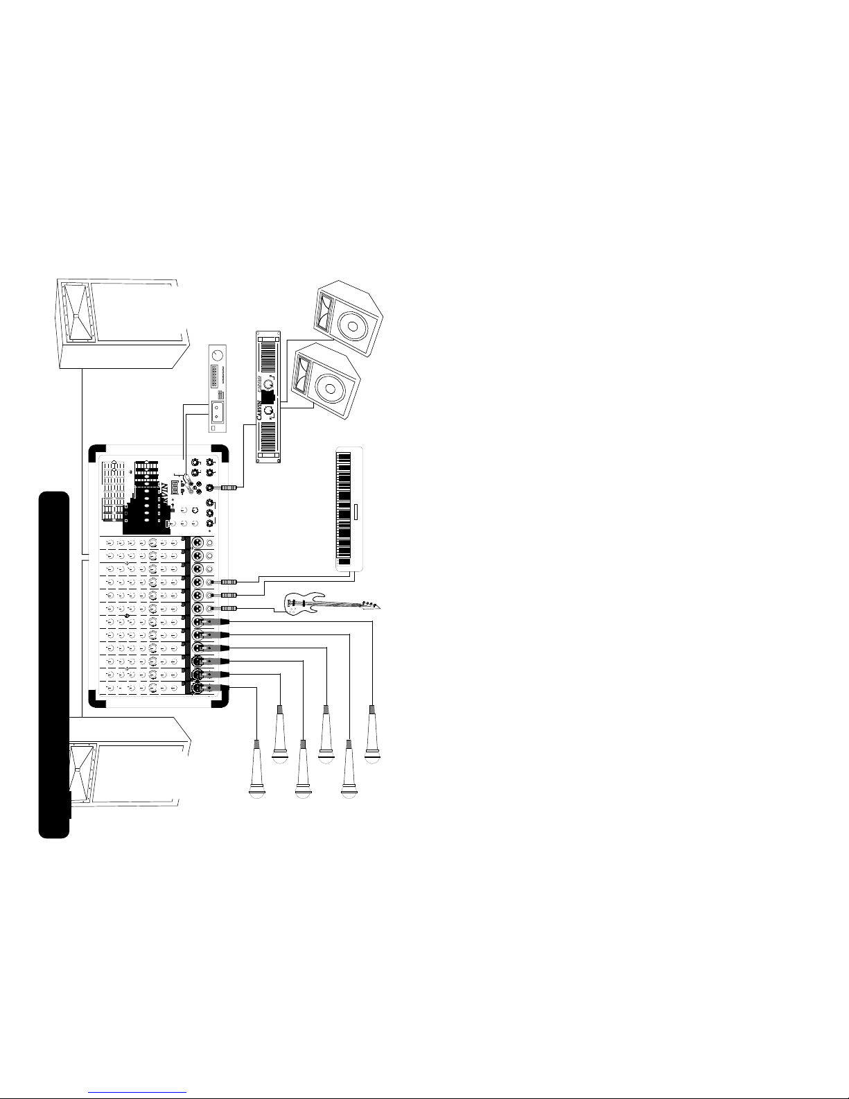
2. CONNECTING SPEAKERS (Powered Models Only)
• Use the right and left 1/4” speaker jacks on the rear panel which are con-
troled by the main level control on the front). The speaker cables should be
non-shielded and at least 18 gauge(AWG) wire. For speaker cable runs of
over 20 feet 16 gauge wire is recommended..
NOTE: Do not run your speakers through microphone wire, gui-
tar cables, or multi-conductor microphone junction boxes or
“snakes” as they are sometimes referred to. This wire is normal-
ly shielded and of a very light gauge causing a substantial loss of
power and oscillations at high frequencies in the amplifier. All
speaker wires must be non-shielded.
3. SpeakerGuardtm and the “PROTECT” LED
• The protect LED comes on along with the output relays in three different pro-
tection modes: Shorted speaker outputs, Speaker Impedance below minimum
rating, and when the amplifier exceeds maximum operating temperature.
• In event the LED comes on turn off the amplifier and Identify and correct any
speaker cable or speaker jack shorts and make sure the total speaker
Impedance for each output is 4 ohms or greater. Also make sure the fan is
not blocked and check that cool air can circulate around the rear of the mixer.
4. CONNECTING INPUTS TO YOUR MIXER
• For low level balanced devices such as microphones, plug into the balanced
MIC inputs using a shielded microphone cable with XLR ends.
• For high level unbalanced devices such as Tape Recorders and Keyboards
plug into the LINE input jacks using a shielded cable with 1/4” phone ends.
5. TURNING YOUR MIXER ON
• Adjust all channel and master level controls to their off positions (fully
counter clockwise).
• Adjust all “EQ” tone controls— the channel’s Hi, Mid, and Bass and the two
master 9 Band Graphic EQ’s to their center detent position.
• Adjust all the Channel “PAN” controls to their center detent position.
• Turn the mixer on by the rear panel power switch and watch for the power
LED to come on. Your mixer is now ready to operate.
QUICK START UP
MAINTENANCE
To bring back the new look, your CX mixer can be washed with mild detergent
and/ or a warm damp soft cloth. This will remove normal dust and oil from the
front and back panels. Never spray cleaners or detergents directly at the unit.
The mixer’s are virtually sealed from outside dust and dirt, but it is recommend-
ed to keep the mixer free from dust, dirt, and moisture as much as possible.

15
Here are two possible speaker connections, two or four 8 ohm speakers with
one or one pair to each 1/4” speaker output. Also two 4 ohm speakers can be
connected one to each speaker output. Never go below 4 ohms on either of the
two speaker output jacks, this would result in premature distortion, thermal shut
down, and/or possible damage to the internal power amplifier.
The basic hook up is simple,
using four (or two stereo)
RCA cables plug the TAPE
SEND on the mixer into the
tape deck’s inputs, and the
mixer’s TAPE RTN’s into the
tape deck’s outputs. With an
effects processor plug the
effects send 1/4”phone output
on the mixer into the input
jack on the effects processor,
and plug one or both (for
stereo) of the L/R EFFECTS
RETURN 1/4” phone inputs
on the mixer into the outputs
on the effects processor.
MADE
AUS
IN THE
RIGHT LEFT
SPEAKERS
4Ω
MINIMUM IMPEDANCE
4Ω
250 250 WATTS
8 OHM MINIMUM
8 OHM MINIMUM
8 OHM MINIMUM
8 OHM MINIMUM
4 OHM MINIMUM 4 OHM MINIMUM
MADE
AUS
IN THE
RIGHT LEFT
SPEAKERS
4Ω
MINIMUM IMPEDANCE
4Ω
250 250 WATTS
L/R MAIN
2
1
010
9
8
7
6
5
4
3
PHANTOM
2
1
010
9
8
7
6
5
4
3
MONITOR
2
1
010
9
8
7
6
5
4
3
DSP EFF RTN
2
1010 9
8
7
6
5
4
3
EFF SEND
2
10109
8
7
6
5
4
3
TAPE / EFF RTN
L
TAPE
RTN
TAPE
SEND
L R
L R
SEND L L R
MONITOREFFECTS LINE OUT
R
127 EFFECTS
RRETURN
POWER
CX1252
AMP
PROTECT
AMP
PATCH
STEREO DSP
BYPASS 1
DELAYS 2-30
REVERB 31-90
CHORUS 91-110
FLANGE 111-128
TWO-TRACK
TAPE RECORDER
AUX EFFECTS PROCESSOR
MONO IN L OUT R
TAPE OUT TAPE IN
SPEAKER CONNECTIONS
TAPE DECKS AND EXTERNAL EFFECTS
4
6. CHANNEL PAN CONTROL
The PAN control adjusts where the channel is heard in
the stereo field of the stereo main outputs. If it is turned
to the extreme left, then the channel will only be heard in
the left main output and similarly only in the right main
output if turned to the extreme right. In the center posi-
tion the channel is heard equally in both the left and right
main outputs. A good starting point for the pan is in the
center position. Then if stereo placement is needed, a
quarter turn to the desired side from the center position
gives a smooth placement in the stereo field, or if desired
a full turn to one side gives a hard placement.
7. CHANNEL EFFECTS/REVERB LEVEL CONTROL
The EFF/REV control adjusts the volume of the channel
going to the effects send master control, and/or the inter-
nal DSP effects (if DSP is present). The effects control is
post channel level. This means adjustments in the chan-
nel’s EQ or level controls will be affecting the effects mix
output of that channel.
8-10. CHANNEL TONE CONTROLS
Each channel features three tone controls LO, MID, and HI. The LO and HI con-
trols are shelving type tone controls with corner frequencies at 100Hz and
10KHz respectively. The shelving means, the for the LO control, all frequencies
from 100Hz down to the lowest frequency the mixer can handle are all boosted
when the knob is turned clockwise and cut when turned counter-clockwise from
the center position. For the HI control the shelving means all the frequencies
from 10kHz and up to the upper limit of the mixer are all boosted when the knob
is turned clockwise and cut when turned counter-clockwise from the center posi-
tion. The MID control is a band pass type of tone control. The band pass
means a middle section of frequences centered around 1.5kHz, but not over
lapping the HI and LO controls, is boosted when the knob is turned clockwise
and cut when turned counter-clockwise from the center position.
Familarity with the channel tone controls:
The three tone controls can add brightness, clairity, and control to the channel’s
input signal. Here are some tonal references for these tone controls.
• LO affects the deep low bass tones and the typical bass tones.
• MID affects all the middle frequencies where the clairty of an average persons
spoken voice is mostly heard. Also the MID incompases the louder sometimes
harsher tones that can distort the over all sound of the system.
• HI affects the treble tones and very high treble tones bringing brightness and
brillance to the channel’s input.
Adjusting:
Use these controls to change the tonal shape of the input signal and in many
cases to reduce possible feedback from microphones near the mixer’s output
speakers. It is suggested the channel tone controls start out in their center
detent position where they do not effect the original incoming signal. Then, if
needed, turn the tone controls (boost,turn to the right, or cut, turn to the left) to
change the sound.
6
7
8
9
10
PAN 0
5
MID
LOW
HI
0
3
6
9
12
3
6
9
12
0
3
6
9
12
3
6
9
12
0
3
6
9
12
3
6
9
12
L R
1
EFF /
REV 5
4
3
2
1
010
9
8
7
6

13
RIGHT
PA CABINET
LEFT
PA CABINET
125 250 50063 1K 2K 4K 8K 16K
L/R MAIN
2
1
010
9
8
7
6
5
4
3
PHANTOM
2
1
010
9
8
7
6
5
4
3
MONITOR
2
1
010
9
8
7
6
5
4
3
DSP EFF RTN
2
10109
8
7
6
5
4
3
EFFSEND
2
10109
8
7
6
5
4
3
TAPE/ EFF RTN
L
TAPE
RTN
TAPE
SEND
L R
L R
SEND L L R
MONITOREFFECTS LINE OUT
R
127 EFFECTS
RRETURN
8 9 10
MON
PAN
11
LEVEL
MON
PAN
L R
0
12
MIC
0
8
4
4
8
–12
+12
0
8
4
4
8
–12
+12
125 250 50063 1K 2K 4K 8K 16K
8 9 10 11 12
POWER
CX1252
5
4
3
2
1
010
9
8
7
6
5
4
3
2
1
010
9
8
7
6
LEVEL
L R
0
MIC
5
4
3
2
1
010
9
8
7
6
5
4
3
2
1
010
9
8
7
6
MON
PAN
LEVEL
0
MIC
5
4
3
2
1
010
9
8
7
6
5
4
3
2
1
010
9
8
7
6
MON
PAN
LEVEL
0
MIC
5
4
3
2
1
010
9
8
7
6
5
4
3
2
1
010
9
8
7
6
MON
PAN
LEVEL
0
MIC
5
4
3
2
1
010
9
8
7
6
5
4
3
2
1
010
9
8
7
6
MON
PAN
LEVEL
0
MIC
5
4
3
2
1
010
9
8
7
6
5
4
3
2
1
010
9
8
7
6
MON
PAN
LEVEL
0
MIC
5
4
3
2
1
010
9
8
7
6
5
4
3
2
1
010
9
8
7
6
MON
PAN
LEVEL
0
MIC
5
4
3
2
1
010
9
8
7
6
5
4
3
2
1
010
9
8
7
6
MON
PAN
LEVEL
0
MIC
5
4
3
2
1
010
9
8
7
6
5
4
3
2
1
010
9
8
7
6
MON
PAN
LEVEL
0
MIC
5
4
3
2
1
010
9
8
7
6
5
4
3
2
1
010
9
8
7
6
MON
PAN
LEVEL
0
MIC
5
4
3
2
1
010
9
8
7
6
5
4
3
2
1
010
9
8
7
6
MON
PAN
LEVEL
0
MIC
5
4
3
2
1
010
9
8
7
6
5
4
3
2
1
010
9
8
7
6
MID
HI
MID
LOW
HI
0
3
6
9
12
3
6
9
12
0
3
6
9
12
3
6
9
12
0
3
6
9
12
3
6
9
12
0
3
6
9
12
3
6
9
12
0
3
6
9
12
3
6
9
12
0
3
6
9
12
3
6
9
12
MID
LOW
HI
0
3
6
9
12
3
6
9
12
0
3
6
9
12
3
6
9
12
0
3
6
9
12
3
6
9
12
MID
LOW
HI
0
3
6
9
12
3
6
9
12
0
3
6
9
12
3
6
9
12
0
3
6
9
12
3
6
9
12
MID
LOW
HI
0
3
6
9
12
3
6
9
12
0
3
6
9
12
3
6
9
12
0
3
6
9
12
3
6
9
12
HI
0
3
6
9
12
3
6
9
12
0
3
6
9
12
3
6
9
12
0
3
6
9
12
3
6
9
12
MID
LOW
HI
0
3
6
9
12
3
6
9
12
0
3
6
9
12
3
6
9
12
0
3
6
9
12
3
6
9
12
MID
LOW
HI
0
3
6
9
12
3
6
9
12
0
3
6
9
12
3
6
9
12
0
3
6
9
12
3
6
9
12
MID
LOW
HI
0
3
6
9
12
3
6
9
12
0
3
6
9
12
3
6
9
12
0
3
6
9
12
3
6
9
12
HI
0
3
6
9
12
3
6
9
12
0
3
6
9
12
3
6
9
12
0
3
6
9
12
3
6
9
12
MID
LOW
HI
0
3
6
9
12
3
6
9
12
0
3
6
9
12
3
6
9
12
0
3
6
9
12
3
6
9
12
MID
LOW
HI
0
3
6
9
12
3
6
9
12
0
3
6
9
12
3
6
9
12
0
3
6
9
12
3
6
9
12
L RL RL RL RL RL RL RL RL RL R
7654321
7654321
EFF/
REV 5
4
3
2
1
010
9
8
7
6
EFF/
REV 5
4
3
2
1
010
9
8
7
6
5
4
3
2
1
010
9
8
7
6
EFF/
REV 5
4
3
2
1
010
9
8
7
6
EFF/
REV 5
4
3
2
1
010
9
8
7
6
EFF/
REV 5
4
3
2
1
010
9
8
7
6
EFF/
REV 5
4
3
2
1
010
9
8
7
6
EFF/
REV 5
4
3
2
1
010
9
8
7
6
5
4
3
2
1
010
9
8
7
6
EFF/
REV 5
4
3
2
1
010
9
8
7
6
EFF/
REV 5
4
3
2
1
010
9
8
7
6
EFF/
REV 5
4
3
2
1
010
9
8
7
6
EFF/
REV
EFF/
REV
-20
dB
MID MID
-20
dB
-20
dB
-20
dB
-20
dB
-20
dB
-20
dB
-20
dB
-20
dB
-20
dB
-20
dB
-20
dB
AMP
PROTECT
LINELINELINELINELINELINE LINELINELINELINELINELINE
AMP
PATCH
R GRAPHIC EQ
L GRAPHIC EQ
STEREODSP
BYPASS 1
DELAYS 2-30
REVERB 31-90
CHORUS 91-110
FLANGE 111-128
MONITOR SPEAKERS
EXTERNAL
POWER AMP
TWO-TRACK
TAPE RECORDER
TO REAR
SPEAKER OUTPUTS
CHANNEL
1
2
3
4
5
6
7
8
91011
12
13
15
17
19
22
30
50
0 dB
PROTECT CHANNELPOWER
1
2
3
4
5
6
7
8
91011
12
13
15
17
19
22
30
50
0 dB
1 2
6
4. TAPE/EFFECTS RETURN LEVEL CONTROL
The TAPE/ EFF RTN control is a stereo effects or tape return volume control. It
can receive input from both the L/R TAPE RTN RCA jacks and the L/R 1/4”
EFFECTS RETURN jacks. This volume controls the return level being fed back
into the master L/R stereo mix. A mono return into the stereo mix can be
achieved by simply feeding the mono signal into both Left and right return jacks.
The stereo return can also be used as just another input to the stereo mix for a
keyboard or other stereo gear.
5. DSP RETURN LEVEL CONTROL
The DSP EFF RTN level control is the stereo output volume control for the inter-
nal digital effects processor. This volume controls the return level being fed
back into the master L/R stereo mix and a smaller amount to the monitor mix.
6. MONITOR LINE OUT JACK
The MONITOR LINE OUT jack is where the monitor mix from the MONITOR
master level control is output. This is a line level output and can be used to drive
an external power amplifier or it can be plugged into one of the AMP PATCH
jacks to drive one of the internal power amplifiers along with its corresponding
graphic EQ.
7. LEFT/RIGHT LINE OUT JACKS
The LEFT/RIGHT LINE OUT jacks are post graphic EQ line output jacks for the
stereo mix. The same signals are also being fed to the internal power amplifier.
Note: If the AMP PATCH jacks are being used for patching the monitor out to
one of the internal amplifiers, then that new signal will also be present on the
corresponding LEFT/RIGHT LINE OUT jack. The stereo mix may still be
accessed at the RCA TAPE SEND jacks if needed.
NOTE : This jack should not be patch into the AMP PATCH jacks, feedback
oscillations with occur.
8. LEFT/RIGHT AMP PATCH JACKS
The LEFT/RIGHT AMP PATCH jacks are pre-graphic EQ and normalized to the
stereo mix L/R MAIN level control. When something is plugged into these jacks,
the stereo mix is disconnected from the graphic EQ and internal power amplifier
allowing the new signal, that was plugged into the jack, to go through the graphic
EQ and to the internal power amplifier. Also, this new signal appears at the cor-
responding LEFT/RIGHT LINE OUT jacks. A typical use for these jacks is in the
case where a powered mono main mix and powered monitor mix are needed.
Here either the left or right main mix can be used for the mono main mix and the
monitor line out jack can be plugged in the opposite AMP PATCH jack for a pow-
ered monitor mix.
9. TAPE SEND AND TAPE RETURN RCA JACKS
The LEFT/RIGHT TAPE SEND RCA jacks deliver the main mix output pre the
graphic EQ uninterrupted by the status of the AMP PATCH jack. If the AMP
PATCH jacks are being used, the TAPE SEND jacks are a way to access the
main mix.
The LEFT/RIGHT TAPE RETURN RCA jacks are RCA inputs to the TAPE/ EFF
RTN level control. These TAPE RETURN jacks can also be used for returning
another effects processor or instrument such as a keyboard to the main mix.

11
to be plugged into the snake or directly into the “LINE” input of the mixer. This
can be accomplished by a high to low impedance adapter or a “Direct box” (both
are available from Carvin or other electronics outlets). Verify that all the connec-
tions are good and that all mics are connected properly. The next step is con-
necting the speakers outputs.
4. POWERED AND NON-POWERED MIXER OUTPUTS
With powered mixers (i.e. mixers with built in power amplifiers) the LEFT and
RIGHT amplifier outputs can NOT be feed through the snake to power the
speakers on stage. Doing this could result in damage to the mixer’s internal
power amp. Only ‘Pre-amp’ signals can be returned to the stage through the
snake. Since speaker level signals cannot be sent through the snake separate
speaker cables must be used. These speaker cables will carry the signal from
the mixer’s power amp outputs directly to the speakers.
With non-powered mixers use the MAIN L/R LINE OUT jacks as the main pre-
amp outputs to drive external power amplifiers. The same snake that was used
to feed the signals from the stage to the mixer usually has provisions for sending
line output signals from the mixer to the stage. The (pre-amp level) MAIN L/R
LINE OUT outputs on the front of the mixer may be plugged into the snake
cable. This will send the signal to the power amplifiers, usually placed on stage.
Once the snake, or alternate means of cabling, carrying the signal has reached
the stage, the connections are made to the power amplifiers. The power amp
outputs can then be connected to the speakers, using 16 gauge (AWG) or heav-
ier non-shielded wire.
Note: Speaker cables are the only ones that should NOT be shielded. All other
cables that carry ‘Mic’ and ‘Pre-amp’ level signals should be shielded. Shielded
cables connected to the power amp outputs can damage the power amplifier.
5. CONNECTING THE MONITOR AMPS AND SPEAKERS
In a typical setup for live sound the MONITOR LINE OUT will be used to provide
a monitor mix for the musicians on stage. The MONITOR LINE OUT output sig-
nal will be sent to the stage just like the main output signals. The signal is sent
to the stage either by using a direct shielded wire from mixer output or by using
the snake. The signal can now be plugged into the inputs of the power ampli-
fiers that will be powering the monitor speakers.
6. TESTING THE MAIN SPEAKERS
It is best to start a new mix with the mixer set as follows: all the channel level
and monitor knobs turned down and the master main level, and master monitor
level turned down (counterclockwise or off). Also it is easier to start with the
channel tone controls turned to their center positions. This way when the system
is turned on and the master is first turned up there will not be any surprises such
as feedback from a microphone or loud signals coming from a channel that was
turned up loud. With the mixer set the main master level can be turned up to a
low level (2 or 3 on the dial). Then a channel with signal can be turned up until it
is heard in the speakers. If no signal is heard from the speakers and the channel
volume is up full, lower the channel volume and check the connections. It may
be the signal source was not plugged in correctly, so try another source. Also it
may be the connections to the speakers or external amplifiers. When the prob-
SELECTING AN EFFECTS PROGRAM (EFFECT)
To select a program use the up or down buttons to scroll to the desired program
number. If you press and hold
either button, after a couple sec-
onds the scrolling rate will increase
ten times. When you are close to
the desired number stop pressing
the button and step through the
last few program numbers to your
desired program. The scroll rate
automatically returns to the slow
speed when the button is not pressed and held.
The last program number select-ed will be saved in non-volatile memory when
power is removed. You do need to wait approximately 30 seconds after chang-
ing the program number before removing power for that number to be saved.
Under normal use this will not be a factor because you will be using the program
selected before removing power.
Note: If both up and down buttons are pressed together, the display will change
and show C01 telling you the MIDI channel is 1. This feature is not used in the
CX mixer series. If this appears, leave the buttons alone for approximately 10
seconds and the display will change back to the last program number used.
SETTING AUDIO LEVELS
Turn all channel EFF/REV level controls to the off position (fully counter clock-
wise). Set the DSP EFF RTN level to 5. Then turn up the channel EFF/REV
level control of the desired channels until the effect level is heard in the stereo
mix. If clipping is heard in the effects, reduce the channel EFF/REV level control
until the clipping is gone. Finally, readjust the DSP EFF RTN level to vary the
amount of effect needed in the stereo mix.
A LITTLE ABOUT THE PRESET PROGRAMS
Bypass: [1] No effect is created. This is used so the effect levels can remain
set even though no effect is wanted at that time.
Delays: [2-30] The delays range from 30mS to 550mS delays with various feed-
back settings from 0 to infinity. Some include a stereo bouncing effect between
the left and right outputs.
Reverbs: [31-60] These natural sounding reverberation effects range from a
short plate reverb to simulating reverberation heard in a cathedral.
Reverbs + Delay: [61-90]These are combinations of the two above effects with
variations in the amount of pre-delay and echo density.
Chorus: [91-110] These are two to six voice stereo choruses, which vary in
delay time, number of echoes, speed and recirculation. Some have reverb.
Flange: [111-128] These are stereo flangers with variations of depth, delay and
speed. Some are followed by a short reverb.
8
CHORUS 91 - 110
FLANGE 111 - 128
1
DELAYS 2 - 30
REVERB 31 - 90
BYPASS
127 EFFECTS
STEREO DSP
INTERNAL DSP EFFECTS

20
Call Toll-Free 800-854-2235 if you need help with your CARVIN product. If you need to return
it for service, our service dept. will issue a Service Number so that we can expect your ship-
ment. Write the Service Number on the carton and be sure to include a full description of
every problem. Package the product to be serviced in its original carton using all its packing
material. Return by UPS pre-paid. Units returned with physical damage, missing parts, or
damage from improper service are not serviceable.
REPAIRS UNDER WARRANTY (1Year)
There is no charge for service under warranty. However, shipping is to be paid both ways by
the customer.
REPAIRS OUT OF WARRANTY
If your warranty has expired, call us for the current flat rate service charge which includes
parts, labor and testing to bring your unit up to factory specifications.
SERVICING IN YOUR AREA
You may select your own service center or have your own qualified technician work on the unit
at your own expense. This will not void the warranty unless damage was done because of
improper servicing. Under the ONE YEAR WARRANTY, Carvin will ship parts pre-paid to you
or your technician providing that the defective part(s) are first returned for our inspection. If you
do not have a qualified service person, we ask that you do not involve yourself in servicing the
unit.
EXTENDED WARRANTY
An extended warranty is available beyond the normal one year period. Please call 1-800-854-
2235 for more information.
LIMITED WARRANTY
Your Carvin Professional Series Product is guaranteed against failure for ONE YEAR. Carvin
will service the unit and supply all parts at no charge to the customer providing the unit is
under warranty. CARVIN DOES NOT PAY FOR PARTS OR SERVICING OTHER THAN
OUR OWN. This warranty is extended to the original purchaser only and is not transferable.
THIS WARRANTY DOES NOT INCLUDE FAILURES CAUSED BY INCORRECT USE,
INADEQUATE CARE OF THE UNIT, OR NATURAL DISASTERS. A COPY OF THE ORIGI-
NAL INVOICE IS REQUIRED TO VERIFY YOUR WARRANTY. Carvin takes no responsibili-
ty for any horn driver or speaker damaged by this unit. This warranty is in lieu of all other war-
ranties, expressed or implied. No representative or person is authorized to represent or
assume for Carvin any liability in connection with the sale or servicing of Carvin products. No
liability is assumed for damage due to accident, abuse, lack of reasonable care, loss of parts,
or failure to follow Carvin’s directions. CARVIN SHALL NOT BE LIABLE FOR INCIDENTAL
OR CONSEQUENTIAL DAMAGES.
In the interest of creating new products and improving existing ones, Carvin is continually researching the latest state of the
art audio design methods, and modern packaging and production techniques. Thus, Carvin reserves the right to make
changes in its products and specifications without notice or obligation.
1-800-854-2235
WARRANTY AND SERVICE INFORMATION
ATTENTION: RISQUE DE CHOC ELECTRIQUE - NE PAS OUVRIR
CAUTION
RISK OF ELECTRIC SHOCK
DO NOT OPEN
CAUTION: TO REDUCE THE RISK OF ELECTRIC SHOCK, DO NOT OPEN CHASSIS; DO NOT DEFEAT OR REMOVE THE
GROUND PIN OF THE POWER CORD; CONNECT ONLY TO A PROPERLY GROUNDED AC POWER OUTLET.
WARNING: TO REDUCE THE RISK OF FIRE OR ELECTRIC SHOCK DO NOT EXPOSE THIS EQUIPMENT TO RAIN OR MOISTURE.
CAUTION: NO USER-SERVICEABLE PARTS INSIDE. REFER SERVICING TO QUALIFIED SERVICE PERSONNEL.
U.K. MAINS PLUG WARNING: A moulded mains plug that has been cut off from the cord in unsafe.
Discard the mains plug at a suitable disposal facility. NEVER UNDER ANY CIRCUMSTANCES
SHOULD YOU INSERT A DAMAGED OR CUT MAINS PLUG INTO A 13 AMP POWER SOCKET.
Do not use the mains plug without the fuse cover in place. Replacement fuse covers can be obtained
from your local retailer. Replacement fuses are 13 amp and MUST be ASTA approved to BS1362.
EXPLANATION
OF SYMBOLS:
“IT IS NECESSARY FOR THE USER TO REFER TO THE INSTRUCTION MANUAL”
“REFERREZ-VOUS AU MANUAL D’UTILISATION”
“UNBEDINGT IN DER BEDIENUNGSANLEITUNG NACHSCHLAGEN”
“DANGEROUS VOLTAGE”
“DANGER HAUTE TENSION”
“GEFAHLICHE SPANNUNG”
IMPORTANT! FOR YOUR PROTECTION, PLEASE READ THE FOLLOWING:
WATER AND MOISTURE: Appliance should not be used near water (e.g. near a bathtub, washbowl,
kitchen sink, laundry tub, in a wet basement, or near a swimming pool, etc). Care should be taken so
that objects do not fall and liquids are not spilled into the enclosure through openings.
POWER SOURCES: The appliance should be connected to a power supply only of the type described
in the operating instructions or as marked on the appliance.
GROUNDING OR POLARIZATION: Precautions should be taken so that the grounding or polarization
means of an appliance is not defeated.
POWER CORD PROTECTION: Power supply cords should be routed so that they are not likely to be
walked on or pinched by items placed upon or against them, paying particular attention to cords at
plugs, convenience receptacles, and the point where they exit from the appliance.
SERVICING: The user should not attempt to service the appliance beyond that described in the oper-
ating instructions. All other servicing should be referred to qualified service personnel.
FUSING: If your unit is equipped with a fuse receptacle, replace only with the same type fuse. Refer
to replacement text on the unit for correct fuse type.
SAFETY INSTRUCTIONS (EUROPEAN)
NOTICE FOR CUSTOMERS IF YOUR UNIT IS EQUIPPED WITH A POWER CORD.
WARNING: THIS APPLIANCE MUST BE EARTHED.
The cores in the mains lead are coloured in accordance with the following code.
GREEN and YELLOW - Earth BLUE - Neutral BROWN - Live
The power cord is terminated in a CEE7/7 plug (Continental Europe). The green / yellow
wire is connected directly to the unit’s chassis. If you need to change the plug, and if you
are qualified to do so, refer to the table below.
WARNING: If the ground is defeated, certain fault conditions in the unit or in the sys-
tem to which it is connected can result in full line voltage between chassis and earth
ground. Severe injury or death can then result if the chassis and the earth ground are
touched simultaneously.
CONDUCTOR WIRE COLOR
NORMAL ALTERNATIVE
LIVELBROWN BLACK
NEUTRALNBLUE WHITE
EARTHEGREEN / YEL GREEN

18
R2 Resistor 5.62K Ohm .25W 1% Metal 50-56231
R3 Resistor 2.21K Ohm .25W 1% Metal 50-22131
R4 Resistor 2.21K Ohm .25W 1% Metal 50-22131
R5 Resistor 47K Ohm .25W 5% Carbon 50-47045
R6 Resistor 10K Ohm .25W 5% Carbon 50-10045
R7 Resistor 100K Ohm .25W 5% Carbon 50-10055
R8 Resistor 300K Ohm .25W 5% Carbon 50-30055
R9 Resistor 100K Ohm .25W 5% Carbon 50-10055
R10 Resistor 10K Ohm .25W 5% Carbon 50-10045
R11 Resistor 300K Ohm .25W 5% Carbon 50-30055
R12 Resistor 2.2K Ohm .25W 5% Carbon 50-22035
R13 Resistor 100K Ohm .25W 5% Carbon 50-10055
R14 Resistor 150K Ohm .25W 5% Carbon 50-15055
R15 Resistor 2.2K Ohm .25W 5% Carbon 50-22035
R16 Resistor 3.3K Ohm .25W 5% Carbon 50-33035
R17 Resistor 4.7K Ohm .25W 5% Carbon 50-47035
R18 Resistor 15K Ohm .25W 5% Carbon 50-15045
R19 Resistor 4.7K Ohm .25W 5% Carbon 50-47035
R20 Resistor 15K Ohm .25W 5% Carbon 50-15045
R21 Resistor 10K Ohm .25W 5% Carbon 50-10045
R22 Resistor 4.7K Ohm .25W 5% Carbon 50-47035
R23 Resistor 10K Ohm .25W 5% Carbon 50-10045
R24 N/U
R25 Resistor 10K Ohm .25W 5% Carbon 50-10045
R26 N/U
R27 Resistor 150K Ohm .25W 5% Carbon 50-15055
R28 Resistor 150K Ohm .25W 5% Carbon 50-15055
R29 Resistor 0 Ohm .50x .20" Jumper 50-00050
R30 Resistor 68K Ohm .25W 5% Carbon 50-68045
R31 Resistor 27K Ohm .25W 5% Carbon 50-27045
R32 Resistor 33K Ohm .25W 5% Carbon 50-33045
R33 Resistor 68K Ohm .25W 5% Carbon 50-68045
R34 Resistor 27K Ohm .25W 5% Carbon 50-27045
R35 Resistor 33K Ohm .25W 5% Carbon 50-33045
R36 Resistor 22K Ohm .25W 5% Carbon 50-22045
R37 Resistor 22K Ohm .25W 5% Carbon 50-22045
R38 Resistor 22K Ohm .25W 5% Carbon 50-22045
R39 Resistor 22K Ohm .25W 5% Carbon 50-22045
R40 Resistor 1K Ohm .25W 5% Carbon 50-10035
R41-43 N/U
R44 Resistor 4.7K Ohm .25W 5% Carbon 50-47035
R46 Resistor 150K Ohm .25W 5% Carbon 50-15055
R47 Resistor 10K Ohm .25W 5% Carbon 50-10045
R48 Resistor 470 Ohm .25W 5% Carbon 50-47025
R49 Resistor 0 Ohm .50x .20" Jumper 50-00050
R50 Resistor 150K Ohm .25W 5% Carbon 50-15055
R51 Resistor 10K Ohm .25W 5% Carbon 50-10045
R52 Resistor 470 Ohm .25W 5% Carbon 50-47025
R53 Resistor 150K Ohm .25W 5% Carbon 50-15055
R54 Resistor 470 Ohm .25W 5% Carbon 50-47025
R55 Resistor 22K Ohm .25W 5% Carbon 50-22045
R56 Resistor 2.2K Ohm .25W 5% Carbon 50-22035
R57 Resistor 150K Ohm .25W 5% Carbon 50-15055
R58 Resistor 470 Ohm .25W 5% Carbon 50-47025
R59 N/U
R60 Resistor 0 Ohm .35x .20" Jumper 50-00035
R61 Resistor 39 Ohm 2W 5% Carbon 54-39005
R62 Resistor 1K Ohm .25W 5% Carbon 50-10035
R63 Resistor 1K Ohm .25W 5% Carbon 50-10035
R70 Resistor 2.4K Ohm .25W 5% Carbon 50-24035
R71 Resistor 150K Ohm .25W 5% Carbon 50-15055
R72 Resistor 2.2K Ohm .25W 5% Carbon 50-22035
R73 Resistor 300K Ohm .25W 5% Carbon 50-30055
R74 Resistor 2.2K Ohm .25W 5% Carbon 50-22035
R75 Resistor 360K Ohm .25W 5% Carbon 50-36055
R76 Resistor 2.2K Ohm .25W 5% Carbon 50-22035
R77 Resistor 110K Ohm .25W 5% Carbon 50-11055
R78 Resistor 1.8K Ohm .25W 5% Carbon 50-18035
R79 Resistor 91K Ohm .25W 5% Carbon 50-91045
R82 Resistor 2.2K Ohm .25W 5% Carbon 50-22035
R83 Resistor 220K Ohm .25W 5% Carbon 50-22055
R84 Resistor 2.4K Ohm .25W 5% Carbon 50-24035
R85 Resistor 180K Ohm .25W 5% Carbon 50-18055
R86 Resistor 2K Ohm .25W 5% Carbon 50-20035
R87 Resistor 130K Ohm .25W 5% Carbon 50-13055
R88 Resistor 2.2K Ohm .25W 5% Carbon 50-22035
R89 Resistor 110K Ohm .25W 5% Carbon 50-11055
R90 Resistor 10K Ohm .25W 5% Carbon 50-10045
R91 Resistor 150K Ohm .25W 5% Carbon 50-15055
R92 Resistor 470 Ohm .25W 5% Carbon 50-47025
R93 Resistor 2.4K Ohm .25W 5% Carbon 50-24035
R94 Resistor 150K Ohm .25W 5% Carbon 50-15055
R95 Resistor 2.2K Ohm .25W 5% Carbon 50-22035
R96 Resistor 300K Ohm .25W 5% Carbon 50-30055
R97 Resistor 2.2K Ohm .25W 5% Carbon 50-22035
R98 Resistor 360K Ohm .25W 5% Carbon 50-36055
R99 Resistor 2.2K Ohm .25W 5% Carbon 50-22035
R100 Resistor 110K Ohm .25W 5% Carbon 50-11055
R101 Resistor 1.8K Ohm .25W 5% Carbon 50-18035
R102 Resistor 91K Ohm .25W 5% Carbon 50-91045
R103 Resistor 1K Ohm .25W 5% Carbon 50-10035
R105 Resistor 2.2K Ohm .25W 5% Carbon 50-22035
R106 Resistor 220K Ohm .25W 5% Carbon 50-22055
R107 Resistor 2.4K Ohm .25W 5% Carbon 50-24035
R108 Resistor 180K Ohm .25W 5% Carbon 50-18055
R109 Resistor 2K Ohm .25W 5% Carbon 50-20035
R110 Resistor 130K Ohm .25W 5% Carbon 50-13055
R111 Resistor 2.2K Ohm .25W 5% Carbon 50-22035
R112 Resistor 110K Ohm .25W 5% Carbon 50-11055
R113 Resistor 10K Ohm .25W 5% Carbon 50-10045
R114 Resistor 150K Ohm .25W 5% Carbon 50-15055
R115 Resistor 470 Ohm .25W 5% Carbon 50-47025
S1 Switch DPDT PUSH PC MTG 25-02201
S2 Switch DPDT PUSH PC MTG MOMENT 25-02202
S3 Switch DPDT PUSH PC MTG MOMENT 25-02202
S4 Switch DPDT PUSH PC MTG 25-02201
U1 DISPLAY 7 SEGMENT 3 DIGIT Red 30-84204
U1 SOCKET IC 6 PIN DISPLAY DX 60-31600
ALL B- Reference designators are 0 ohm jumpers
PART DESCRIPTION (Parts without PCB REF. DES)
3
2
1
46
9
7
5
8
# DESCRIPTION CARVIN # QTY
Switch Cap Grey Extended 07-01603 15
Knob 11 D shaft (COLOR) 07-120-- ---
Front Panel PCB (12 Chan) 30-12524-1 1
Power Module 500Watts 80-05028 1
Heatsink Bracket 2.5" 10-12527 2
DSP Reverb PCB 80-02105 1
Speaker Output PCB 30-12524-3 1
Fuse Holder slow blow see fuse chart 1
Yellow
Green
Drk Grey
20
25
28
Color Knob Code
toroid transformer 600Watts 15-60120 1
1.
2.
3.
4.
5.
6.
7.
8.
9.
1
PAGE
RECEIVING INSPECTION .....................................................................i
FOR THE NEW OWNER .......................................................................i
TABLE OF CONTENTS ........................................................................1
GETTING STARTED QUICKLY.............................................................2
MAINTENANCE..................................................................................2
CHANNEL FEATURES ......................................................................3,4
MASTER SECTION FEATURES..........................................................5-7
INTERNAL DSP EFFECTS PROCESSOR.................................................8
INTERNAL DSP EFFECTS PROGRAMS CHART .....................................9
SETTING UP YOUR SOUND SYSTEM ..........................................10--12
SAMPLE PA SYSTEM CONFIGURATIONS.....................................13-14
SPEAKER CONNECTIONS ................................................................15
TAPE DECKS AND EXTERNAL EFFECTS ............................................15
BLOCK DIAGRAM............................................................................16
CX MIXER PARTS LIST ...............................................................17,18
CX MIXER TECHNICAL SPECIFICATIONS..........................................19
FUSE SELECTION..............................................................................19
WARRANTY INFORMATION ............................................................20
TABLE OF CONTENTS

16
THREE BAND
CHANNEL TONE
CONTROLS
PAD
-20dB
PAD SWITCH
HI MID LOW
MIC
PRE
CHANNEL
LEVEL CHANNEL
EFF SND
CHANNEL
MONITOR
LEVEL
L
R
MON
EFF
EFFECTS
SUMMING AMP EFFECTS
SEND 2
LEVEL
MAIN RIGHT
SUMMING AMP
AND LEVEL
MAIN LEFT
SUMMING AMP
AND LEVEL
EFFECTS
SEND 2
GAINSTAGE
NINE BAND
GRAPHIC
EQUILIZER
LEFT
LINE OUT
RIGHT
LINE OUT
NINE BAND
GRAPHIC
EQUILIZER
EFFECTS
SEND 2
INTERNAL
DSP SEND
GAIN
REDUCTION
FOR DSP
MONITOR
SUMMING AMP
MONITOR
LINE OUT
LEFT
AMP PATCH
RIGHT
AMP PATCH
DSP RETURN LEFT
DSP RETURN RIGHT
EFFECTS RETURN LEFT
EFFECTS RETURN RIGHT
EFF INPUT LEFT
TAPE RTN RIGHT
TAPE RTN LEFT
STEREO RETURN
FOR INTERNAL
STEREO DSP
RIGHT
TAPE OUT
LEFT
TAPE OUT
TO INTERNAL
POWER AMP
PAN
DSP TO
MONITOR
EFF INPUT RIGHT
1155 Industrial Ave.
Escondido, CA
92029
619-747-1710
FAX 747-9065
CX 1252 & CX842
BLOCK DIAGRAM
Part No Date Revised
CHANNEL
line pad
(-26dB)
3
1. LINE INPUT JACK
The LINE input is a 1/4” phone jack designed for unbalanced line and instrument
level inputs. Examples of these inputs would be instruments such as a guitar, a
keyboard, an unbalanced mic, or a pre-amp output. The line input can be used
at the same time the mic input is being used.
2. XLR MICROPHONE INPUT
The XLR MIC input is designed for balanced low imped-
ance ( microphone ) input signals. The balance means
the input differential amplifier will reduce the common
noise picked up on the microphone cables. The XLR
connector is wired as per the industry standard, pin 1 is
ground, pin 2 is non-inverting (positive), and pin 3 is
inverting (negative).
Phantom power is available on every XLR input jack
when the phantom power switch in the master section is
pressed. This feature allows condenser microphones to
be run directly from the mixer.
Note: When using phantom power make sure the phan-
tom power is switched off before connecting or discon-
necting microphones to the mixer. It is recommended to
allow 5 seconds for the phantom power to discharge
before making any microphone connections. Also, to
avoid hearing a pop, turn down the master volume when
turning on the phantom power.
3. -20DB PAD SWITCH
This switch reduces the input gain on both the line and mic input jacks by 20dB.
If distortion is heard regardless of the channel LEVEL control’s setting engage
this switch. This will eliminate the over-driving of the input amplifier before the
channel LEVEL control.
4. CHANNEL LEVEL CONTROL
The LEVEL control adjusts the final volume of the channel before going to the
Pan control. Here is where the individual channel volumes are adjusted to make
up the desired mix heard at the main outputs. A general rule to prevent distor-
tion with in the mixer, is to always keep the MAIN master level the same or high-
er than the channel LEVEL.
5. MONITOR LEVEL CONTROL
The MONITOR level control adjusts the volume of the channel going to the mon-
itor mix. Here is where the individual channel monitor volumes are adjusted to
make up the desired mix heard at the monitor output. The monitor level control
is pre channel level and pre channel tone controls. This means it is unaffected
by adjustments in channel level and tone controls. The purpose for this is so the
main mix adjustments for tone and level can be made without disturbing the
monitor mix.
1
2
3
4
5
MON
LEVEL
MIC
5
4
3
2
1
010
9
8
7
6
5
4
3
2
1
010
9
8
7
6
L R
1
-20
dB
LINE
CHANNEL FEATURES

14
125 250 50063 1K 2K 4K 8K 16K
L/R MAIN
2
1
010
9
8
7
6
5
4
3
PHANTOM
2
1
010
9
8
7
6
5
4
3
MONITOR
2
1
010
9
8
7
6
5
4
3
DSP EFF RTN
2
10109
8
7
6
5
4
3
EFFSEND
2
1010
9
8
7
6
5
4
3
TAPE/ EFF RTN
L
TAPE
RTN
TAPE
SEND
L R
L R
SEND L L R
MONITOREFFECTS LINE OUT
R
127 EFFECTS
RRETURN
8 9 10
MON
PAN
11
LEVEL
MON
PAN
L R
0
12
MIC
0
8
4
4
8
–12
+12
0
8
4
4
8
–12
+12
125 250 50063 1K 2K 4K 8K 16K
8 9 10 11 12
POWER
CX1252
5
4
3
2
1
010
9
8
7
6
5
4
3
2
1
010
9
8
7
6
LEVEL
L R
0
MIC
5
4
3
2
1
010
9
8
7
6
5
4
3
2
1
010
9
8
7
6
MON
PAN
LEVEL
0
MIC
5
4
3
2
1
010
9
8
7
6
5
4
3
2
1
010
9
8
7
6
MON
PAN
LEVEL
0
MIC
5
4
3
2
1
010
9
8
7
6
5
4
3
2
1
010
9
8
7
6
MON
PAN
LEVEL
0
MIC
5
4
3
2
1
010
9
8
7
6
5
4
3
2
1
010
9
8
7
6
MON
PAN
LEVEL
0
MIC
5
4
3
2
1
010
9
8
7
6
5
4
3
2
1
010
9
8
7
6
MON
PAN
LEVEL
0
MIC
5
4
3
2
1
010
9
8
7
6
5
4
3
2
1
010
9
8
7
6
MON
PAN
LEVEL
0
MIC
5
4
3
2
1
010
9
8
7
6
5
4
3
2
1
010
9
8
7
6
MON
PAN
LEVEL
0
MIC
5
4
3
2
1
010
9
8
7
6
5
4
3
2
1
010
9
8
7
6
MON
PAN
LEVEL
0
MIC
5
4
3
2
1
010
9
8
7
6
5
4
3
2
1
010
9
8
7
6
MON
PAN
LEVEL
0
MIC
5
4
3
2
1
010
9
8
7
6
5
4
3
2
1
010
9
8
7
6
MON
PAN
LEVEL
0
MIC
5
4
3
2
1
010
9
8
7
6
5
4
3
2
1
010
9
8
7
6
MID
HI
MID
LOW
HI
0
3
6
9
12
3
6
9
12
0
3
6
9
12
3
6
9
12
0
3
6
9
12
3
6
9
12
0
3
6
9
12
3
6
9
12
0
3
6
9
12
3
6
9
12
0
3
6
9
12
3
6
9
12
MID
LOW
HI
0
3
6
9
12
3
6
9
12
0
3
6
9
12
3
6
9
12
0
3
6
9
12
3
6
9
12
MID
LOW
HI
0
3
6
9
12
3
6
9
12
0
3
6
9
12
3
6
9
12
0
3
6
9
12
3
6
9
12
MID
LOW
HI
0
3
6
9
12
3
6
9
12
0
3
6
9
12
3
6
9
12
0
3
6
9
12
3
6
9
12
HI
0
3
6
9
12
3
6
9
12
0
3
6
9
12
3
6
9
12
0
3
6
9
12
3
6
9
12
MID
LOW
HI
0
3
6
9
12
3
6
9
12
0
3
6
9
12
3
6
9
12
0
3
6
9
12
3
6
9
12
MID
LOW
HI
0
3
6
9
12
3
6
9
12
0
3
6
9
12
3
6
9
12
0
3
6
9
12
3
6
9
12
MID
LOW
HI
0
3
6
9
12
3
6
9
12
0
3
6
9
12
3
6
9
12
0
3
6
9
12
3
6
9
12
HI
0
3
6
9
12
3
6
9
12
0
3
6
9
12
3
6
9
12
0
3
6
9
12
3
6
9
12
MID
LOW
HI
0
3
6
9
12
3
6
9
12
0
3
6
9
12
3
6
9
12
0
3
6
9
12
3
6
9
12
MID
LOW
HI
0
3
6
9
12
3
6
9
12
0
3
6
9
12
3
6
9
12
0
3
6
9
12
3
6
9
12
L RL RL RL RL RL RL RL RL RL R
7654321
7654321
EFF/
REV 5
4
3
2
1
010
9
8
7
6
EFF/
REV 5
4
3
2
1
010
9
8
7
6
5
4
3
2
1
010
9
8
7
6
EFF/
REV 5
4
3
2
1
010
9
8
7
6
EFF/
REV 5
4
3
2
1
010
9
8
7
6
EFF/
REV 5
4
3
2
1
010
9
8
7
6
EFF/
REV 5
4
3
2
1
010
9
8
7
6
EFF/
REV 5
4
3
2
1
010
9
8
7
6
5
4
3
2
1
010
9
8
7
6
EFF/
REV 5
4
3
2
1
010
9
8
7
6
EFF/
REV 5
4
3
2
1
010
9
8
7
6
EFF/
REV 5
4
3
2
1
010
9
8
7
6
EFF/
REV
EFF/
REV
-20
dB
MID MID
-20
dB
-20
dB
-20
dB
-20
dB
-20
dB
-20
dB
-20
dB
-20
dB
-20
dB
-20
dB
-20
dB
AMP
PROTECT
LINELINELINELINELINELINE LINELINELINELINELINELINE
AMP
PATCH
R GRAPHIC EQ
L GRAPHIC EQ
STEREODSP
BYPASS 1
DELAYS 2-30
REVERB 31-90
CHORUS 91-110
FLANGE 111-128
FROM LEFT
SPEAKER OUTPUT
MONO (LEFT)
PA CABINET
MONO (LEFT)
PA CABINET
MONITOR TO
AMP PATCH (R)
CABLE
MONITOR SPEAKERS
(RIGHT) SPEAKER OUTPUT
FROM RIGHT
SPEAKER OUTPUT
5
1. MAIN MASTER LEVEL CONTROL
The L/R MAIN master control is the master volume control for the main stereo
mix. This volume receives its signals from the channel pan controls. If the AMP
PATCH jacks are not being used, then this is also the master volume control
feeding the Graphic EQ, the main line out jacks, and the internal stereo power
amplifier (in the powered mixer version).
2. MONITOR MASTER LEVEL CONTROL
The MONITOR master level control is the master volume for the monitor mix
heard in the monitor output. This volume receives its signals from the channel
monitor level controls.
3. EFFECT SEND MASTER LEVEL CONTROL
The EFF SEND master control is the master volume for the effects send mix
heard in the effects send output. The volume gets its signals from the
effects/reverb control on the channels. The typical use of effects send mix it to
drive external Effects processors, but it can also be used as another stage moni-
tor mix if needed.
1
2
3
10
6
8
5
13
11
12
7
9
4
127 EFFECTS
CHORUS 91 - 110
FLANGE 111 - 128
1
DELAYS 2 - 30
REVERB 31 - 90
BYPASS
STEREO DSP
0
8
4
4
8
–12
+12
125 250 50063 1K 2K 4K 8K 16K
L/R MAIN
PHANTOM
2
1
010
9
8
7
6
5
4
3
MONITOR DSP EFF RTN
EFF SEND TAPE / EFF RTN
L
TAPE
RTN
TAPE
SEND
L R
L R
SEND L L R
MONITOREFFECTS LINE OUT
R
RRETURN
0
8
4
4
8
–12
+12
125 250 50063 1K 2K 4K 8K 16K
POWER
CX1252
PROTECT
AMP
PATCH
R GRAPHIC EQ
L GRAPHIC EQ
2
1
010
9
8
7
6
5
4
3
2
1
010
9
8
7
6
5
4
3
2
1
010
9
8
7
6
5
4
3
2
1
010
9
8
7
6
5
4
3
2
1
010
9
8
7
6
5
4
3
MASTER SECTION FEATURES

12
lem has been corrected start again with turning up the low level signal and use
this low level signal to check if all the speakers are working. Now the main sys-
tem is ready for the sound check.
7. TESTING THE MONITOR AMPLIFIER AND SPEAKERS
Each input channel of the mixer has a knob labeled MON. This knob is used to
adjust the volume of each channel’s send to the monitor buss.
The channel monitor signal is pre the channel tone controls and the channel
level control. What this means is any adjustments to the channel tone controls
or the channel level control will not effect the monitor mix. The advantage of this
is, if more high frequencies are wanted in the main mix speakers from one chan-
nel, turning up the HI tone control will not result in feedback in the monitors.
With the mixer set as suggested in section 6, the MONITOR master level can be
brought up to 5 or 6 on the dial and a channel, with signal, can have its monitor
level turned up until it is heard in the monitors. If nothing is heard in the monitors
first make sure the channel does have signal. One way to test the signal is to
turn it up in the main speakers. If the signal is present in the mains, but not in
the monitors then turn them both down again and start checking the monitor sys-
tem connections from the mixer output to the amplifiers and speakers. When the
problem has been corrected start again with turning up the level and use the sig-
nal to check that all the monitor speakers are working. Now the monitor system
is ready for the sound check.
8. THE SOUND CHECK
The sound check takes some skill, but mostly patience from the performers and
especially you the system operator. If you get frustrated during the sound check
the performers can lose confidence and the sound may suffer due to things
missed in the sound check. The basic sound check follows this format: First test
all microphones and other input devices(direct boxes, etc.) before the performers
are included in the sound check. A good thing to also check here is feedback in
the monitors from the microphones. Good positioning of the monitors and the
use of a graphic equalizer before the monitor power amp solves most major
monitor feedback problems. Now for a sound check with the performers. First
set the level of each performers individually and in cases where a performer has
multiple microphones, such as with a drummer, set each drum mic individually
then the drum set as a whole. This is also a good time to make some channel
tone control adjustments to tailor the sound of the individual performers and
instruments. Next after setting each individual have the performers run through
a song or a portion of the show. Don’t hesitate to stop the performers if some-
thing needs to be adjusted or if an individual performer or microphone needs to
be heard solo again. Remember the sound check is not a rehearsal, but a sys-
tem check, a time to work the bugs out of the system so the show can go
smoothly. It is always a good idea for the mixer operator to have a microphone
to inform the performers of what is needed during the sound check. If a monitor
system is being used, the mixer operator’s microphone should only be heard
through the monitors when addressing the on stage performers, especially if
something needs to be checked during the show. If the sound check is allowed
to run through its full course, the system should run smoothly at show time.
7
The RCA jacks are Ideal for using a cassette deck to record a mix with using the
TAPE SEND jacks and playing it back through the TAPE RETURN jacks with out
using up any channels for play back or having to use adapters to hook up the
cassette deck.
10. PROTECT LED
The PROTECT LED indicates the internal relays have disengaged the amplifiers
from the speaker output jacks on the rear panel. The LED is not used in the non-
powered versions.
There are three instances that will engage the protection circuitry.
The first is in the case of a short on the speaker outputs. The second is if the
total speaker impedance is lower than the minimum impedance rating. And the
third is if the maximum operating temperature of the power amplifier is exceeded
due to poor air circulation and/or over-loading.
11. POWER LED
The Power LED indicates when the mixer is powered up.
12. PHANTOM POWER SWITCH AND LED
The PHANTOM power switch turns on the microphone phantom power in the
channel XLR jacks. This power is used for supplying a bias voltage to condenser
microphones. The LED indicates the phantom power is turned on. The phantom
power will not damage dynamic microphones.
13. THE GRAPHIC EQUALIZER
Each mixer has two nine band graphic EQ’s (equalizer). The graphic EQ’s are
dedicated to the left and right outputs following (or post) the amp patch jacks of
the mixer. The 9 band Graphic EQ’s provide a wide degree of tonal flexibility.
The Frequencies:
Here are some tonal reference ranges for the individual sliders to help relate the
frequencies in hertz to perceived tonal changes.
In order from left to right:
-the 63 Hz slider effects deep sub bass levels.
-the 125 Hz is typical bass adjustments.
-the 250, 500 and 1K Hz are for low mid and high mid adjustments.
-the 2K and 4K Hz are for lower treble adjustments.
-the 8K and 16K Hz are for the very high treble adjustments.
Adjusting:
When the sliders are in their center detent position they do not affect the audio
signal. When a slider is raised or lowered from the center position, it boost and
cuts respectively the level of a narrow frequency band assigned to that particular
slider. It is recommended that all sliders are set in their center position before
equalizing your tone. Typically low frequency feedback is in the 125 and 250 Hz
range while high feedback is in the 2k and 4k Hz range. Occasionally one fre-
quency (slider) of the equalizer will have to be pulled down to -12dB to stop feed-
back. If many of the sliders have to be pulled down to stop feedback, the place-
ment of the speakers with respect to the microphones may need to be reconsid-
ered. As much as possible, try to have the main speaker facing away from and in
front of the microphones not on stage behind them. The graphic EQ is mainly
used to “equalize” the response of the main room and reduce feedback from
microphones. Don’t be afraid to use the Graphic EQ, but take care not to over-

EFF # DESCRIPTION
1BYPASS No audio output
2DELAY 33mS w/ 11% regeneration
3DELAY 33mS w/ 17% regeneration
4DELAY 33mS w/ 25% regeneration
5DELAY 33mS w/ 32% regeneration
6DELAY 33mS w/ 44% regeneration
7DELAY 55mS w/ no regeneration
8DELAY 55mS w/ 11% regeneration
9DELAY 55mS w/ 17% regeneration
10 DELAY 55mS w/ 25% regeneration
11 DELAY 55mS w/ 32% regeneration
12 DELAY 55mS w/ 44% regeneration
13 DELAY 89mS w/ no regeneration
14 DELAY 89mS w/ 11% regeneration
15 DELAY 89mS w/ 17% regeneration
16 DELAY 89mS w/ 25% regeneration
17 DELAY 89mS w/ 32% regeneration
18 DELAY 89mS w/ 44% regeneration
19 DELAY 100mS w/ no regeneration
20 DELAY 100mS w/ 17% regeneration
21 DELAY 100mS w/ 25% regeneration
22 DELAY 100mS w/ 44% regeneration
23 DELAY 222mS w/ no regeneration
24 DELAY 222mS w/ 37% regeneration
25 DELAY 333mS w/ no regeneration
26 DELAY 333mS w/ 37% regeneration
27 DELAY 444mS w/ no regeneration
28 DELAY 444mS w/ 37% regeneration
29 DELAY 555mS w/ no regeneration
30 DELAY 555mS w/ 37% regeneration
31 REVERB Percussion Plate 0.5s decay
32 REVERB Percussion Plate 0.7s decay
33 REVERB Percussion Plate 1.3s decay
34 REVERB Percussion Plate 2.4s decay
35 REVERB Percussion Plate 3.1s decay
36 REVERB Percussion Plate 3.9s decay
37 REVERB Vocal Plate 0.5s decay
38 REVERB Vocal Plate 0.7s decay
39 REVERB Vocal Plate 1.3s decay
40 REVERB Vocal Plate 2.4s decay
41 REVERB Vocal Plate 3.1s decay
42 REVERB Vocal Plate 3.9s decay
43 REVERB Small Room 0.5s decay
44 REVERB Small Room 0.7s decay
45 REVERB Small Room 1.3s decay
46 REVERB Small Room 2.4s decay
47 REVERB Small Room 3.1s decay
48 REVERB Small Room 3.9s decay
49 REVERB Medium Room 0.5s decay
50 REVERB Medium Room 0.7s decay
51 REVERB Medium Room 1.3s decay
52 REVERB Medium Room 2.4s decay
53 REVERB Medium Room 3.1s decay
54 REVERB Medium Room 3.9s decay
55 REVERB Large Room 0.5s decay
56 REVERB Large Room 0.7s decay
57 REVERB Large Room 1.3s decay
58 REVERB Large Room 2.4s decay
59 REVERB Large Room 3.1s decay
60 REVERB Large Room 3.9s decay
61 DLY& REV 33mS Predelay Percussion Plate 0.5s
62 DLY& REV 33mS Predelay Percussion Plate 0.7s
63 DLY& REV 33mS Predelay Percussion Plate 1.3s
64 DLY& REV 33mS Predelay Percussion Plate 2.4s
65 DLY& REV 33mS Predelay Percussion Plate 3.1s
EFF # DESCRIPTION
66 DLY& REV 33mS Predelay Percussion Plate 3.9s
67 DLY& REV 55mS Predelay Vocal Plate 0.5s
68 DLY& REV 55mS Predelay Vocal Plate 0.7s
69 DLY& REV 55mS Predelay Vocal Plate 1.3s
70 DLY& REV 55mS Predelay Vocal Plate 2.4s
71 DLY& REV 55mS Predelay Vocal Plate 3.1s
72 DLY& REV 55mS Predelay Vocal Plate 3.9s
73 DLY& REV 89mS Predelay Small Room 0.5s
74 DLY& REV 89mS Predelay Small Room 0.7s
75 DLY& REV 89mS Predelay Small Room 1.3s
76 DLY& REV 89mS Predelay Small Room 2.4s
77 DLY& REV 89mS Predelay Small Room 3.1s
78 DLY& REV 89mS Predelay Small Room 3.9s
79 DLY& REV 100mS PredelayMedium Room 0.5s
80 DLY& REV 100mS PredelayMedium Room 0.7s
81 DLY& REV 100mS PredelayMedium Room 1.3s
82 DLY& REV 100mS PredelayMedium Room 2.4s
83 DLY& REV 222mS PredelayMedium Room 3.1s
84 DLY& REV 222mS PredelayMedium Room 3.9s
85 DLY& REV 333mS PredelayLarge Room 0.5s
86 DLY& REV 333mS PredelayLarge Room 0.7s
87 DLY& REV 444mS PredelayLarge Room 1.3s
88 DLY& REV 444mS PredelayLarge Room 2.4s
89 DLY& REV 555mS PredelayLarge Room 3.1s
90 DLY& REV 555mS PredelayLarge Room 3.9s
91 CHORUS Slow & Shallow
92 CHORUS Medium & Shallow
93 CHORUS Fast & Shallow
94 CHORUS Slow & Deeper
95 CHORUS Medium & Deeper
96 CHORUS Fast & Deeper
97 CHORUS Slow & Deep
98 CHORUS Medium & Deep
99 CHORUS Slow & Really Deep
100 CHORUS Medium & Really Deep
101 CHORUS#91 33mS Predelay Percussion Plate 1.3s
102 CHORUS#92 33mS Predelay Percussion Plate 2.4s
103 CHORUS#93 33mS Predelay Percussion Plate 3.1s
104 CHORUS#94 33mS Predelay Percussion Plate 3.9s
105 CHORUS#95 55mS Predelay Vocal Plate 0.5s
106 CHORUS#96 55mS Predelay Vocal Plate 0.7s
107 CHORUS#97 55mS Predelay Vocal Plate 1.3s
108 CHORUS#98 55mS Predelay Vocal Plate 2.4s
109 CHORUS#99 55mS Predelay Vocal Plate 3.1s
110 CHORUS#100 55mS Predelay Vocal Plate 3.9s
111 FLANGE Slow & 6mS depth
112 FLANGE Medium & 6mS depth
113 FLANGE Fast & 6mS depth
114 FLANGE Slow & 13mS depth
115 FLANGE Medium &13mS depth
116 FLANGE Fast &13mS depth
117 FLANGE Slow & 24mS depth
118 FLANGE Medium & 24mS depth
119 FLANGE Slow & 40mS depth
120 FLANGE Medium & 40mS depth
121 FLANGE#111 55mS Predelay Percussion Plate 1.3s
122 FLANGE#112 55mS Predelay Percussion Plate 2.4s
123 FLANGE#113 55mS Predelay Percussion Plate 3.1s
124 FLANGE#114 55mS Predelay Percussion Plate 3.9s
125 FLANGE#115 55mS Predelay Vocal Plate 0.5s
126 FLANGE#116 55mS Predelay Vocal Plate 0.7s
127 FLANGE#117 55mS Predelay Vocal Plate 1.3s
128 FLANGE#118 55mS Predelay Vocal Plate 2.4s
910
This section is a brief overview of what it takes to hook up a sound system using
a CX series mixer. The overview will include some of the different possible set-
ups and some basics on how to mix live sound. If you are new to using mixers
you should find this section very informative in helping you to operate your sound
system properly. If you are experienced with mixers then you may find some of
the information new or presented with a new approach that can help you as well.
As always, experimentation is the key to success, so don’t be afraid to use the
controls to get a feel for what they do.
1. INPUT CONNECTIONS FROM THE STAGE
For a live sound reinforcement public address system (P.A. System), the input
signals to the mixer will come from the microphones and instruments on the
stage. Each microphone or instrument to be amplified by the P.A. system must
be connected to one of the mixing console inputs. It is preferred to have as
many of the stage instruments as possible plugged into the mixer. This allows
the best overall sound control of the instruments as they are mixed together and
then amplified by the P.A. system.
2. ON STAGE OPERATION
The CX Series mixers are small enough to have on the stage. The advantages
to this are: a band member can operate the mixer so no extra person is needed;
all the cables for microphones, instruments, and speakers are short and plug
directly into the mixer; and there are no cables for the audience to trip over. The
only disadvantages are the band member/mixer operator on stage doesn’t hear
what the audience is hearing, and because the mixer operator is a band member
he can not react fast to problems with the P.A. system such as feedback and
sudden volume differences.
3. REMOTE TO STAGE OPERATION
Many times the mixer will be located a distance from the stage. This allows the
performance to be monitored and mixed from the audience’s perspective.
Monitoring at a distance from the stage usually means employing a multi-cable
cable or more commonly referred to as a “Snake” (available from CARVIN).
Each of the microphones and instruments are plugged into the snake box at the
stage and the snake cable carries all these signals to the mixer. At the mixer
the snake cable, which fans out to plugs corresponding to the jacks on the snake
box, is plugged into the appropriate inputs and line level (pre-amp) outputs of the
mixer. All snake cables are numbered, both on the snake box and the cable, to
help keep track of which microphones are being plugged into which channels. It
is a good idea at this point to label each of the console channels according to
what instrument they will be controlling. This can be done with masking tape
(Scotch brand #230 drafting tape) or another suitable ‘light’ sticking tape. The
tape provides a replaceable surface to write on. The (XLR) balanced low imped-
ance format will ensure you the best possible performance and lowest possible
noise when operating with long cable lengths, such as a snake. However, many
times an unbalanced output (1/4 inch phone plug type) from an instrument needs
SETTING UP THE SOUND SYSTEM
INTERNAL DSP EFFECTS PROGRAM CHART
This manual suits for next models
1
Table of contents
Other CARVIN Music Mixer manuals

CARVIN
CARVIN C3248 User manual

CARVIN
CARVIN XP650 User manual

CARVIN
CARVIN C1600 User manual

CARVIN
CARVIN C1648 User manual

CARVIN
CARVIN STUDIO MATE SM162 User manual

CARVIN
CARVIN MX2488 User manual

CARVIN
CARVIN XP880 User manual

CARVIN
CARVIN SL User manual

CARVIN
CARVIN C3248 User manual

CARVIN
CARVIN XP1000L User manual

CARVIN
CARVIN XP800L User manual

CARVIN
CARVIN M600 User manual

CARVIN
CARVIN C1240 User manual

CARVIN
CARVIN PA410 User manual

CARVIN
CARVIN DXMIXER User manual

CARVIN
CARVIN C1644(P User manual

CARVIN
CARVIN S16 User manual

CARVIN
CARVIN MX2488 User manual

CARVIN
CARVIN RX 1200 User manual

CARVIN
CARVIN XP800L User manual